TMEM87a/Elkin1, a component of a novel mechanoelectrical transduction pathway, modulates melanoma adhesion and migration
- EMBL Australia Node in Single Molecule Science, School of Medical Sciences, University of New South Wales, Australia
- Cellular and Systems Physiology, School of Medical Sciences, University of New South Wales, Australia
- Max Delbrück Center for Molecular Medicine, Germany
- Victor Chang Cardiac Research Institute, Australia
- St Vincent’s Clinical School, University of New South Wales, Australia
- Freie Universität Berlin, Institute of Chemistry and Biochemistry, Germany
- ARC Centre of Excellence in Advanced Molecular Imaging, University of New South Wales, Australia
Figures
Figure 1 with 2 supplements

Measuring MA currents in WM266-4 melanoma cells.
(A) Schematic of pillar array experiment. Cells were cultured on top of an array of elastomeric cylinders. Whole-cell patch-clamp was used to study the currents within the cell when stimuli were applied directly at the cell-substrate matrix by serially deflecting an individual pilus subjacent to the cell. (B) Bright-field image of a WM266-4 cell (outlined by dashed, yellow line) cultured on top of a pillar array. The microelectrode is outlined in white and the stimulating probe in blue. Scale bar = 10 µm. (C) Representative traces of inward MA currents activated in WM266-4 cells in response to increasing deflections. (D) Average current-voltage relationships of deflection-activated currents in WM266-4 cells (mean ± s.e.m., n = 5 cells). (E) Stimulus-response plots for WM266-4 cells on uncoated arrays (mean ± s.e.m., n = 10 cells) and WM266-4 cells on pillar arrays coated with LM511 (n = 20 cells). WM266-4 cells on LM511-coated arrays were more sensitive to pillar deflections than WM266-4 cells on uncoated arrays (ordinary two-way ANOVA, n = 20 and 10 cells respectively, **p=0.005; Sidak’s multiple comparison, *p=0.02). (F) Transwell analysis of LM isoforms and their ability to promote transmigration. Note, LM511 supported the highest degree of transmigration, in comparison with other LM isoforms, LM111, LM211, LM411 and EHS-LM. See Figure 1—figure supplement 1 for a comparison of mechanically evoked currents in WM115 versus WM266-4 cells and Figure 1—figure supplement 2 for analysis of PIEZO1 contribution of mechanically evoked currents in WM266-4 cells.
-
Figure 1—source data 1
Source data for details of current kinetics.
- https://cdn.elifesciences.org/articles/53308/elife-53308-fig1-data1-v4.docx
Figure 1—figure supplement 1

MA currents in melanoma cell lines.
(A) Example traces of MA currents activated by pillar deflections in WM115 cells and in WM266-4 cells. (B) Stimulus-response curves of MA current activation in WM115 cells vs WM266-4 cells. WM266-4 cells were more sensitive to pillar deflections, in comparison with WM115 cells, on uncoated arrays (ordinary two-way ANOVA, n = 10 and 8 cells respectively, *p=0.04; Sidak’s multiple comparison, *p=0.01).
Figure 1—figure supplement 2
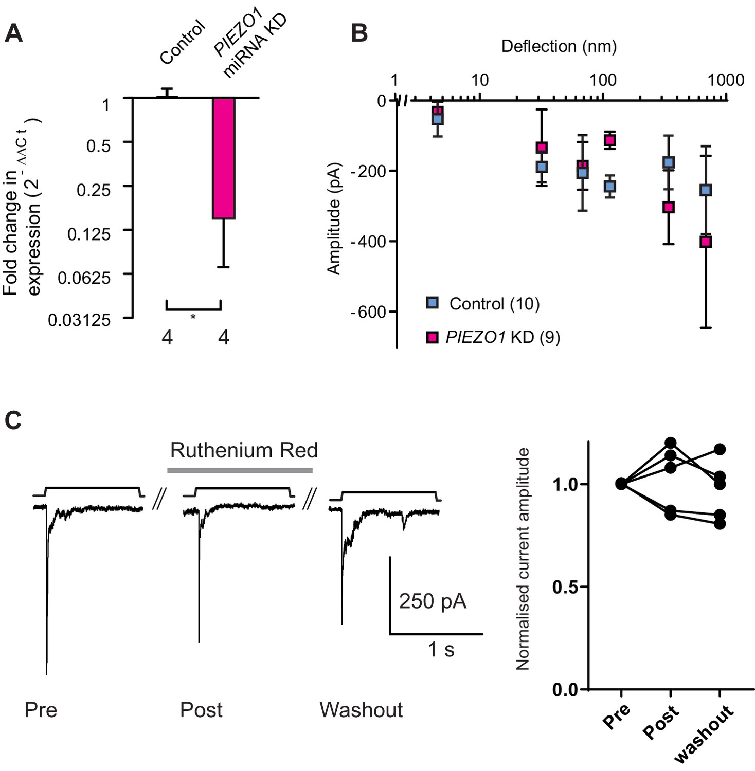
Knockdown of PIEZO1 in WM266-4 cells.
(A) A qPCR analysis shows that levels of PIEZO1 transcript were significantly reduced in WM266-4 cells when these cells were transfected with a plasmid encoding miRNA targetting PIEZO1 transcript (Mann-Whitney, control n = 4, KD n = 4, *p=0.0286). (B) Despite the decrease in PIEZO1 transcript, the stimulus-response curve in PIEZO1 KD cells did not differ from the controls. (C) Deflection-evoked currents are not inhibited by Ruthenium Red (RR). Mechanical currents were evoked in WM266-4 cells then RR (30 µM) was flowed onto cells for 3 min and a second stimulus applied, a final stimulus was applied after RR had been washed out for 2 min. Quantification of current amplitude reveals no block of mechanically-evoked currents by RR.
Figure 2 with 4 supplements
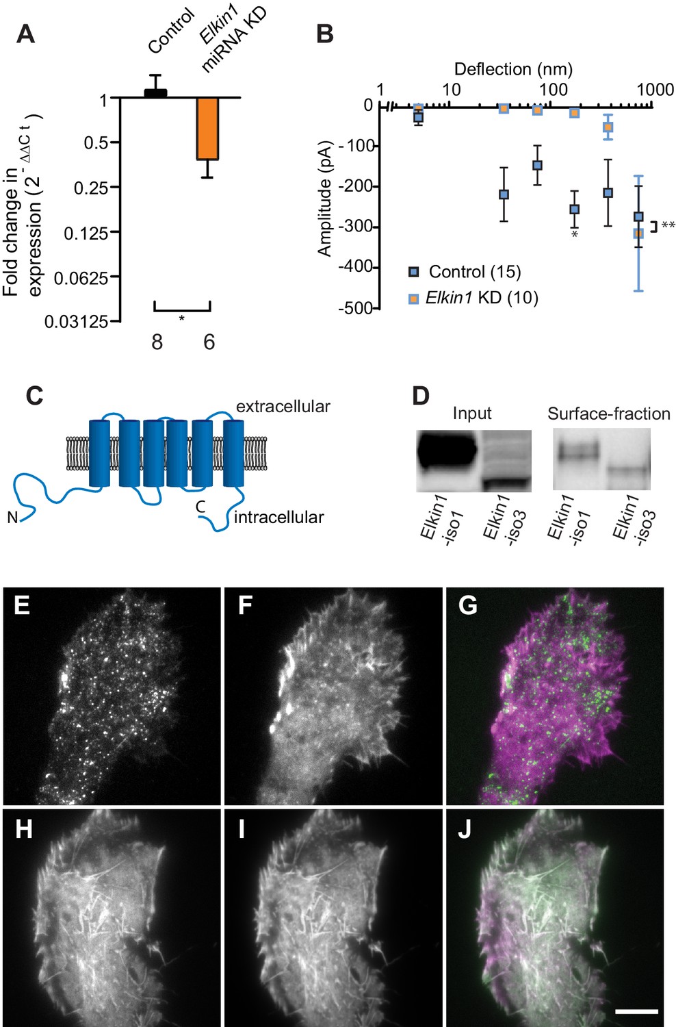
TMEM87a/Elkin1 in WM266-4 cells.
(A) Transfection of WM266-4 cells with a plasmid encoding miRNA targeting Elkin1 leads to a reduction in Elkin1 transcript (Mann-Whitney, control n = 8, KD n = 6, *p=0.013). (B) Knockdown of Elkin1 leads to a significant decrease in MA currents in WM266-4 cells, in comparison with controls (two-way ANOVA, control n = 15, Elkin1 KD = 10, **p=0.004; Sidak’s multiple comparison, *p=0.02) (data presented as mean ± s.e.m.). (C) Transmembrane topology prediction of hsElkin1-iso1, with 6 TM domains (highest probability prediction of TM domains). (D) Western-blot analysis of samples prepared from HEK-293T cells overexpressing hsElkin1-isoform1 or hsElkin1-isoform3. The surface fraction was isolated by pull-down of biotinylated proteins after surface labelling. Note, both hsElkin1-isoform1 and hsElkin1-isoform3 are present at the cell surface. See Figure 2—figure supplement 1 for full blot. TIRF images of (E) hsElkin1-iso1-GFP, (F) Lifeact mCherry and (G) overlay in WM266-4 cells. Note that hsElkin1-iso1 is present in foci as well as the plasma membrane. TIRF images of (H) hsElkin1-iso3-GFP, (I) Lifeact mCherry and (J) overlay in WM266-4 cells. Note that hsElkin1-iso3 is present in the plasma membrane and associated with actin structures. Scale bar 10 µm. See Figure 2—videos 1 and 2 for corresponding live-cell imaging and Figure 2—figure supplement 2 for laser scanning confocal imaging of hsElkin1-iso1/hsElkin1-iso3 with a Golgi-RFP marker.
Figure 2—figure supplement 1
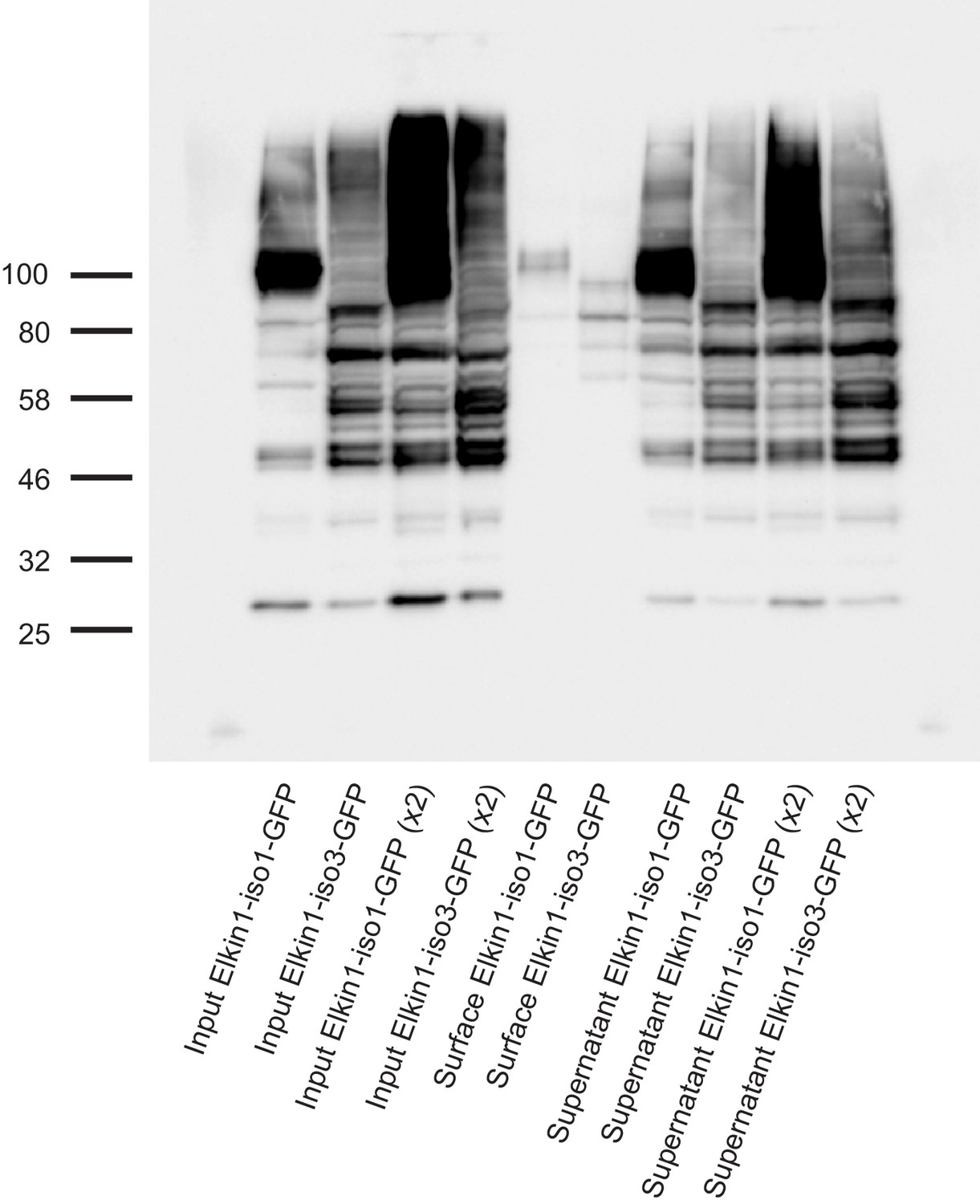
Cell-surface biotinlyation of hsElkin1-GFP fusion proteins.
hsElkin1-iso1-GFP or hsElkin1-iso3-GFP were overexpressed in HEK-293T P1KO cells. Cells were biotinylated and the cell-surface fraction isolated by pulldown of biotinylated proteins using Neutravidin beads. Input samples, the surface fraction and the supernatant were separated using SDS-PAGE, transferred to a PVDF membrane and Elkin-1-GFP fusion proteins were detected using an anti-GFP antibody. Both hsElkin1-iso1 and hsElkin1-iso3 were present in the plasma membrane fraction, as well as the supernatant.
Figure 2—figure supplement 2

Visualisation of hsElkin1-iso1 and -iso3 with laser-scanning confocal microscopy.
WM266-4 cells were transfected with plasmids encoding hsElkin1-iso1-GFP (A) or hsElkin1-iso3-GFP (D). Cells were additionally transduced with a vector encoding a Golgi-RFP marker (B,E). Overlays are presented in (C,F). It is clear that hsElkin1-iso1 localises partially, but not exclusively, to the Golgi. Scale bar, 10 µm.
Figure 2—video 1
hsElkin1-iso1-GFP dynamics in WM266-4 cells, as visualised with TIRF microscopy.
Time-lapse TIRF images of WM266-4 cells expressing hsElkin1-iso1-GFP (green) and lifeact-mCherry (magenta). Scale bar 10 μm.
Figure 2—video 2
hsElkin1-iso3-GFP dynamics in WM266-4 cells, as visualised with TIRF microscopy.
Time-lapse TIRF images of WM266-4 cells expressing hsElkin1-iso3-GFP (green) and lifeact-mCherry (magenta). Scale bar 10 μm.
Figure 3 with 2 supplements
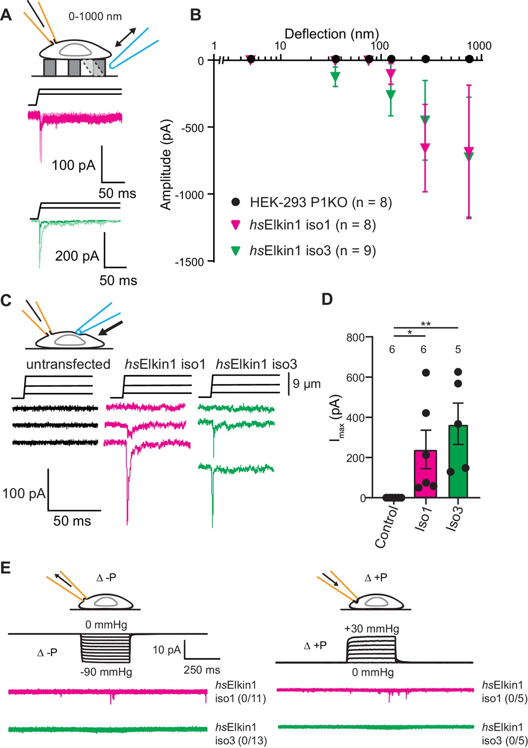
Elkin1-dependent currents can be activated in HEK-293T P1KO cells.
(A) Example traces of Elkin1-dependent MA currents in HEK-293T P1KO cells (magenta: hsElkin1-iso1; green: hsElkin1-iso3). (B) Stimulus-response plots of HEK-293T P1KO cells (black circles, n = 8), HEK-293T P1KO cells expressing hsElkin1-iso1 (magenta triangles, n = 8) or hsElkin1-iso3 (green triangles, n = 9) (data are mean ± s.e.m.). Note that no currents were observed in the HEK-293T P1KO cells within the stimulus range of 1–1000 nm. (C) Example traces of indentation-activated MA currents in HEK-293T P1KO cells: control (black), hsElkin1-iso1 (magenta), hsElkin1-iso3 (green). Note that no MA currents are activated in response to indentation in HEK-293T P1KO cells in the absence of Elkin1. (D) Maximal current amplitude of indentation-activated currents was significantly larger in cells expressing hsElkin1-isoform1 or hsElkin1-isoform3 versus control cells (Student’s t-test, control (n = 6) versus hsElkin1-isoform1 (n = 6) *p=0.03, control versus hsElkin1-isoform3 (n = 5) **p=0.003). Data are presented as mean ± s.e.m. with individual points overlaying bar graphs. (E) Example traces of cell-attached patch clamp recordings of Elkin-1 expressed in HEK-293T P1KO cells. Pressure stimuli ranging from 0 to -90 mmHg and 0 to +30 mmHg were applied using HSPC. Note that no stretch-activated currents were measured in any of the cells (negative pressure: control (black) = 0/8 cells, hsElkin 1-iso1 (magenta) = 0/11 cells, hsElkin1-iso3 (green) = 0/13 cells; positive pressure hsElkin 1-iso1 (magenta) = 0/5 cells and hsElkin1-iso3 (green) = 0/5 cells) Cartoons of stimuli adapted from Rocio Servin-Vences et al. (2017). See Figure 3—figure supplement 1 for analysis of Elkin1 activation in a second cell line (N2a Piezo1-/-), Figure 3—figure supplement 2 for HSPC analysis of PIEZO1 expressed in HEK-293T P1KO cells.
-
Figure 3—source data 1
Physiological properties of currents recorded in HEK-293 P1KO cells.
- https://cdn.elifesciences.org/articles/53308/elife-53308-fig3-data1-v4.docx
Figure 3—figure supplement 1
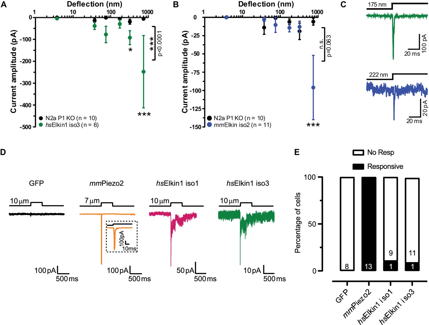
Electrophysiological characterisation of hsElkin1-iso1, hsElkin1-iso3 and mmElkin1.
Mechanically-evoked currents can be measured when hsElkin1-iso3 (A) or mmElkin1 (B) are expressed in N2aPiezo1-/- cells. Overall differences between hsElkin1-iso3 and N2aPiezo1-/- cells as well as between mmElkin1 and N2aPiezo1-/- cells were tested with a two-way ANOVA and Bonferroni post-hoc tests (*p<0.05, **p<0.001, ***p<0.0001). Average data is depicted as mean ± SEM. (C) Example current traces of hsElkin1 iso3 (green) and mmElkin1 (blue). Note that example traces have different y-axes. (D) GFP (black), mmPiezo2 (orange), hsElkin iso1 (magenta) and iso3 (green) were overexpressed in N2aPiezo1-/- cells. Cells were clamped at −60 mV and exposed to cell indentation. No currents were evoked in cells expressing GFP, all cells expressing mmPiezo2 responded to indentation but mechanically-evoked currents could be measured in cells expressing hsElkin iso1 or iso3. (E) Percentage of transfected N2aPiezo1-/- cells that responded to membrane indentation. The numbers in bars indicate the number of cells tested.
Figure 3—figure supplement 2

High speed pressure clamp recordings in cells expressing hsPIEZO1.
(A) Example traces of cell attached patch clamp recordings of PIEZO1 expressed in HEK-293T cells: positive and negative pressure stimuli were applied. (B) Maximal current amplitude of stretch-activated currents. Data are presented as mean ± s.e.m. with individual data points overlayed. Open circles: negative pressure, closed circles: positive pressure.
Figure 4 with 2 supplements
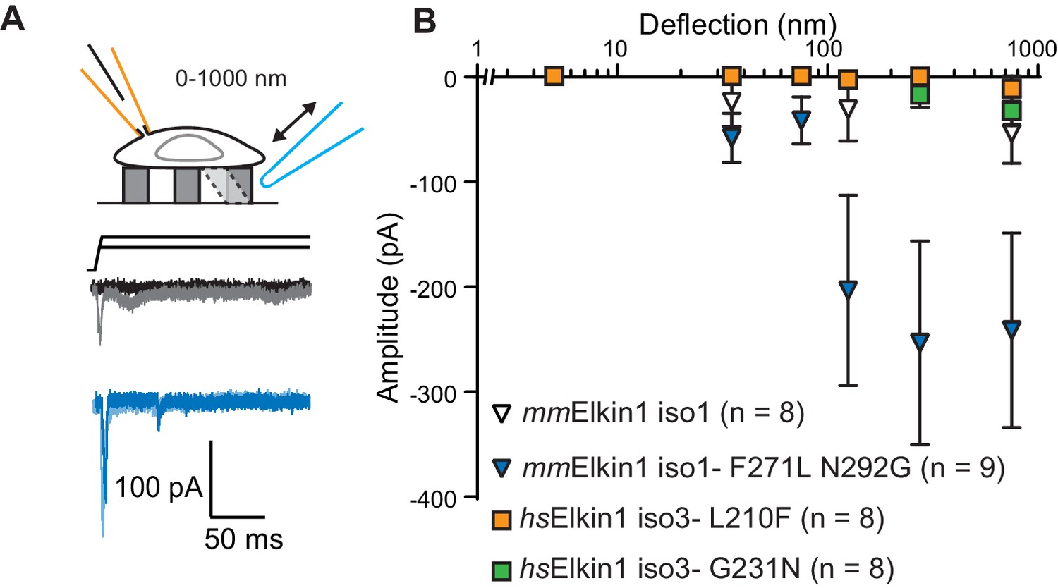
hsElkin1 and mmElkin1-dependent currents exhibit distinct mechano-sensitivity.
(A) Example traces of M. musculus Elkin1-dependent MA currents in HEK-293T P1KO cells (grey: mmElkin1-iso1; blue mmElkin1-iso1 F271L N292G). (B) Stimulus-response plots of HEK-293T P1KO cells expressing: mmElkin1-iso1 (open triangles, n = 8 cells), mmElkin1-iso1 F271L N292G (blue triangles, n = 9 cells), hsElkin1-iso3 L210F (orange squares, n = 8 cells), hsElkin1-iso3 G231N, (green squares, n = 8 cells). Data points presented as mean ± s.e.m. Cartoons of stimuli adapted from Rocio Servin-Vences et al. (2017). See Figure 4—figure supplement 1 for sequence alignment of hsElkin1 and mmElkin1, Figure 4—figure supplement 2 for surface biotinylation analysis of Elkin1 variants and Figure 4—source data 1 for details on current kinetics.
-
Figure 4—source data 1
Source data for details of current kinetics.
- https://cdn.elifesciences.org/articles/53308/elife-53308-fig4-data1-v4.docx
Figure 4—figure supplement 1
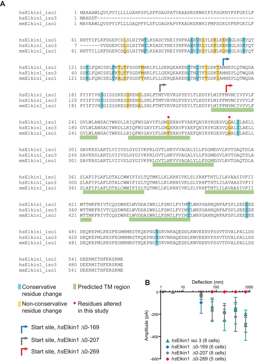
Sequence alignment of human and mouse Elkin1 protein and the effect of N-terminal deletions on hsElkin1 function.
(A) Sequence alignment of the human (hs) Elkin1-iso1 and -iso3 against the mouse (mm) Elkin1 protein. The predicted transmembrane regions are marked with green, conservative residue variations in teal and non-conservative residue variations in yellow. The two residues that have been studied here are marked with a magenta star. Arrows indicate the start site for cloned truncation proteins. (B) Stimulus-response curve analysis of hsElkin1-iso3 versus hsElkin1 truncation mutants. Note that function is only lost once the first predicted TM domain is disrupted.
Figure 4—figure supplement 2
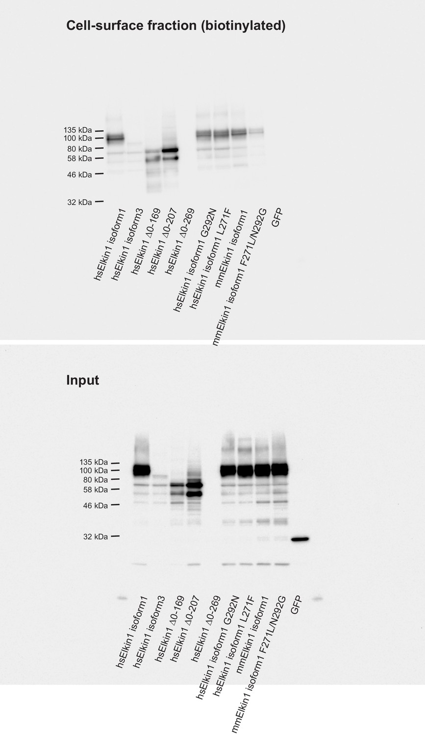
Cell-surface biotinlyation of Elkin1-GFP fusion proteins.
GFP-tagged Elkin1 variants were overexpressed in HEK-293T P1KO cells. Cells were biotinylated and the cell-surface fraction isolated by pulldown of biotinylated proteins using Neutravidin beads. Input samples and the surface fraction were separated using SDS-PAGE, transferred to a PVDF membrane and Elkin-1-GFP fusion proteins were detected using an anti-GFP antibody. Human (hs) Elkin1 isoforms 1 and 3 and truncations ∆0–169, ∆0–207 were all detected in the plasma membrane. The Elkin1-iso1 mouse (mm) variant, and the mutated hs variants (G292N and L271F) that did not respond efficiently to deflection stimuli were still present in the plasma membrane fraction, as was the mouse variant F271L, N292G. As such, the differences in mechanically activated currents that depend on these isoforms cannot be explained by a change in localisation of the protein. In contrast, the lack of activity of the human ∆0–269 variant can be attributed to a lack of stability of the protein, as this variant is no longer detected in the input samples, or the plasma membrane.
Figure 5 with 1 supplement
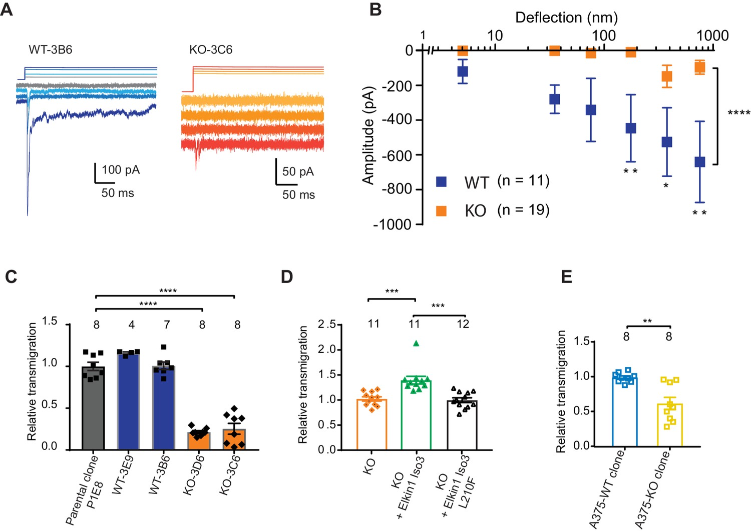
CRISPR/Cas9 deletion of Elkin1 inhibits MA currents and migration of WM266-4 cells.
(A) Example traces of MA currents in WT and Elkin1-KO clones of WM266-4 cells on LM511-coated pillar arrays. A residual current is present in Elkin1-KO clones at large deflections. (B) Stimulus-response plots showing that MA currents are significantly inhibited in the Elkin1-KO clones in comparison with the WT clones (ordinary two-way ANOVA, Elkin1 KO = 19 cells, WT = 11 cells, ****p<0.0001; Sidak’s multiple comparison, **p=0.007, *p=0.03, **p=0.004). (Data displayed as mean ± s.e.m.). (C) A transwell analysis of migration onto LM511-coated membranes shows that WT clones (3B6 and 3E9) were indistinguishable from WT controls, whereas Elkin1-KO clones (3C6 and 3D6) exhibited significantly reduced transmigration (one-way ANOVA, parental control n = 8 wells, 3E9 = 4 wells, 3B6 = 7 wells, 3D6 = 8 wells, 3C6 = 8 wells, ****p<0.0001; Dunnett’s multiple comparisons, control vs 3C6, ****p<0.0001; control vs 3D6, ****p<0.0001, samples normalised against WT control). (D) The transmigration phenotype in the KO was rescued by overexpression of hsElkin1-iso3, but not hsElkin1-iso3-L210F (one-way ANOVA, KO control n = 11 wells, +hsElkin1-iso3 = 12 wells, +hsElkin1-iso3-L210F = 11 wells, ****p<0.0001; Dunn’s multiple comparisons, Control vs +hsElkin1-iso3, ***p=0.0006; +hsElkin1-iso3 vs +hsElkin1-iso3-L210F, ***p=0.0002, samples normalised against KO control). (E) In the A375 melanoma cell line, an Elkin1-KO clone also exhibited a significant decrease in transmigration onto LM511, in comparison with a WT control (unpaired t-test with Welch’s correction, WT and Elkin1-KO = 8 wells, **p=0.002, samples normalised against WT control). (C–E) Individual data points overlay mean ± s.e.m. See Figure 5—figure supplement 1 for CRISPR/Cas9 strategy and knockout clone validation.
Figure 5—figure supplement 1
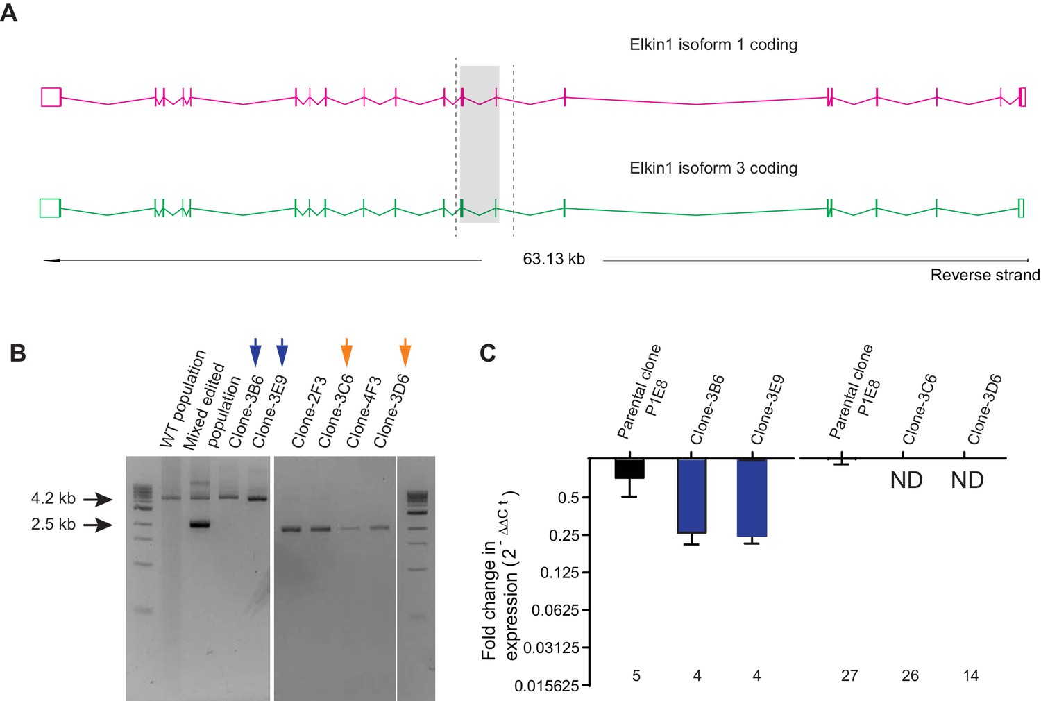
CRISPR/Cas9 editing of WM266-4 cells.
(A) Schematic representation of Elkin1 gene. Elkin1 is located on the reverse strand, Chromosome 15: 42,210,452–42,273,663. The CRISPR-Cas9 nickase was used in order to counter off-target effects that can arise from using the nuclease and gRNAs were designed using the web-base CRISPR design tool from the Zhang laboratory MIT (http://crispr.mit.edu/). The editing strategy used two gRNAs targeting intron seven and two gRNAs targeting exon 9, to create a deletion of 1.7 kb from chromosome 15. Screening primers for gPCR are marked with dashed lines. (B) Gel electrophoresis of gPCR products. The WT yields a band 4.2 kb in length. The band corresponding to successful editing is 2.5 kb in length. In the mixed edited population both bands are visible. Isolated clones 3B6 and 3E9 (marked with blue arrows) were selected as WT clones. Clones 3C6 and 3D6 (marked with orange arrows) were selected as Elkin1-KO clones. (C) a qPCR analysis of mRNA isolated from individual clones confirms that Elkin1 transcript is detected in the WT clones, but is not detected in the Elkin1-KO clones.
Figure 6 with 1 supplement
Elkin1-KO cells exhibit decreased migration on 2D and quasi-1D substrates.
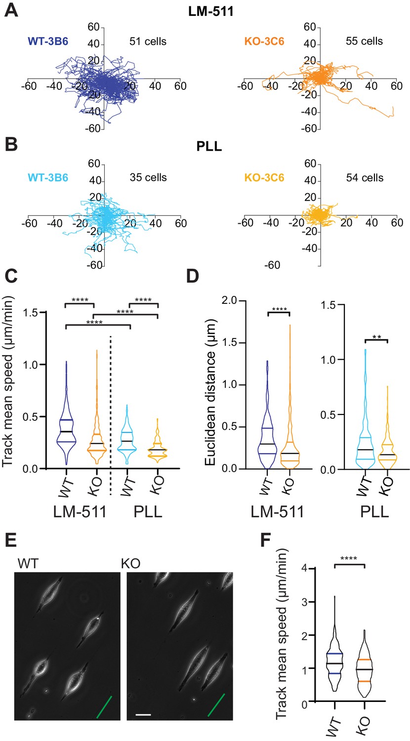
(A) Example tracks of cell movement on LM511 substrates of representative WT (3B6, 51 cells) and Elkin1-KO clones (3C6, 55 cells). (B) Example tracks of cell movement PLL substrates of representative WT and Elkin1-KO clones (3B6 = 35 cells, 3C6 = 54 cells). (C) The Elkin1-KO clones exhibited a significant decrease in mean track speed in comparison with WT clones on LM511 (Mann-Whitney, WT = 246 tracks, Elkin1-KO = 340 tracks, ****p<0.0001) and on PLL (Mann-Whitney, WT = 240 tracks, Elkin1-KO = 241 tracks, ****p<0.0001). In addition, WT clones exhibited a significantly higher mean track speed on LM511 compared with PLL (Mann-Whitney, LM511 n = 246 tracks, PLL = 240 tracks, ****p<0.0001) and the Elkin1-KO clones exhibited a significantly higher mean track speed on LM511 compared with PLL (Mann-Whitney, LM511 n = 340 tracks, PLL = 241 tracks, ****p<0.0001). See Figure 6—figure supplement 1 for supporting experiments conducted using GFP-labelled cells. (D) The Euclidean distance calculated for the Elkin1-KO clones was significantly lower than WT clones on LM511 (Mann-Whitney, WT = 246 tracks, Elkin1-KO = 340 tracks, ****p<0.0001) and PLL globally coated substrates (Mann-Whitney, WT = 240 tracks, Elkin1-KO = 241 tracks, **p=0.0020). (E) Representative images of WT and Elkin1-KO clones attached to quasi-1D LM511 substrates, green line indicates direction of printed stripes, scale bar = 20 µm. (F) Elkin1-KO clones exhibited a significantly decreased mean track speed, in comparison with the WT clones (Mann-Whitney test, WT = 260 tracks, Elkin1-KO = 275 tracks, ****p<0.0001). (C,D,F) Data displayed as violin plots to represent relative distribution of data, black lines indicate median and coloured lines indicate quartiles. See Figure 6—source data 1 for further details.
-
Figure 6—source data 1
Source data for migration speeds and distances.
- https://cdn.elifesciences.org/articles/53308/elife-53308-fig6-data1-v4.docx
Figure 6—figure supplement 1

GFP-expressing Elkin1-KO cells exhibit decreased migration on 2D substrates, in comparison with WT cells.
The WM266-4 Elkin1-KO cells expressing cytoplasmic-GFP exhibited a significant decrease in mean track speed in comparison with similarly labelled WM266-4 WT clones on LM-511 (Mann-Whitney, WT = 419 tracks, Elkin1-KO = 435 tracks, ****p<0.0001), 38% reduction in the mean of the Elkin1-KO track mean speed. The track mean speed was also decrease in the WM266-4 Elkin1-KO cells expressing GFP on PLL, in comparison with WT controls (Mann-Whitney, WT = 458 tracks, Elkin1-KO = 275 tracks, ****p<0.0001), 21% reduction in the mean of the Elkin1-KO track mean speed.
Figure 7 with 4 supplements
Elkin1-KO increases cell dissociation from organotypic spheroids.
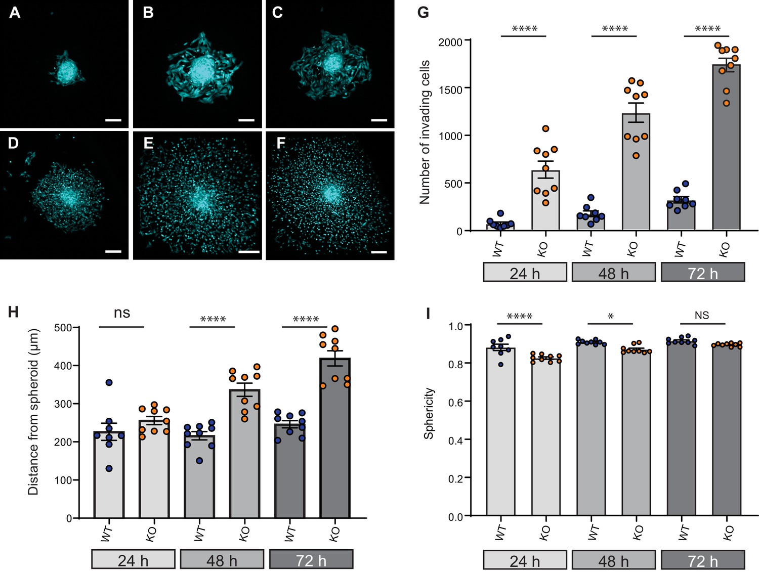
(A–C) Representative images of WT spheroids at 24 (A), 48 (B) and 72 (C) h post-implantation in 3D collagen I gel. See Figure 7—videos 1 and 2 for live imaging of 0–12 hr post-implantation. (D–F) Representative images of Elkin1-KO spheroids at 24 (D), 48 (E), and 72 hr (F). Scale bars = 200 µm. (G) At all time points the number of Elkin1-KO cells that had dissociated from the spheroid was higher than for the WT cells. Data is presented as the mean ± s.e.m. with individual points representing the average number of invading cells for each spheroid (one-way ANOVA with Tukey’s multiple comparison, WT = 9, Elkin1-KO = 9, 24, 48, 72 hr ****p=0.0001). (H) Average distance of cells from the edge of the spheroid. Data are presented as mean ± s.e.m. of distance from spheroid with overlay of points representing the average for each individual experiment The average distance per spheroid was significantly different at 48 and 72 hr, but not 24 hr (one-way ANOVA with Tukey’s multiple comparison: WT = 9 spheroids, Elkin1-KO = 9 spheroids, 24 h p=0.78; 48 hr, ****p<0.0001; 72 hr, ****p<0.0001). See Figure 7—figure supplement 1A for data representing all individual cells. (I) Sphericity of cells that had invaded the collagen gel. Data are average sphericity of all cells within the collagen gel at each time point, presented as bar graphs with mean ± s.e.m. with an overlay of average for each spheroid measured. The WT cells were significantly more spherical than the Elkin1-KO clones at 24 and 48 hr (one-way ANOVA with Tukey’s multiple comparison, WT = 9 spheroids, Elkin1-KO = 9 spheroids, 24 hr, ****p<0.0001; 48 hr, *p=0.012; 72 hr, NS, p=0.46). See Figure 7—figure supplement 1B for data representing all individual cells, Figure 7—figure supplement 2 for migration data corresponding to isolated cells in 3D collagen gels and Figure 7—source data 1 for further details.
-
Figure 7—source data 1
Source data for 3D migration properties.
- https://cdn.elifesciences.org/articles/53308/elife-53308-fig7-data1-v4.docx
Figure 7—figure supplement 1

Data from all individual cells invading collagen gels from organotypic spheroids.
(A) Distance from spheroid at each time point for each cell and (B) sphericity of each cell at the given time point. data are presented as violin plots, black mid-line represents the median, coloured lines the quartiles.
Figure 7—figure supplement 2

The effect of Elkin1 deletion on migration in 3D collagen gels.
(A) The mean track speed of WT and Elkin1-KO clones in 3D collagen gel was not significantly different (Mann-Whitney, WT = 3135 tracks, Elkin1-KO = 1599 tracks, p=0.65). (B) However, the Elkin1-KO cells exhibit a less spherical (more elongated) morphology over the course of the experiment (Mann-Whitney, WT = 3135 measurements, Elkin1-KO = 1599 measurements, ***p=0.0006). (C) The straightness of the Elkin1-KO tracks was reduced in comparison with WT tracks (Mann-Whitney, WT = 3135 tracks, Elkin1-KO = 1599 tracks, ****p<0.0001). Data displayed as violin plots (center line, median).
Figure 7—video 1
Dissociation of WM266-4 WT cells in organotypic spheroid assay.
Time-lapse confocal imaging of WM266-4 WT spheroids embedded in a collagen I gel. Imaging started at 30 min post-implantation and images were obtained every 30 min for 12 hr.
Figure 7—video 2
Dissociation of WM266-4 Elkin1-KO cells in organotypic spheroid assay.
Time-lapse confocal imaging of WM266-4 Elkin1KO spheroids embedded in a collagen I gel. Imaging started at 30 min post-implantation and images were obtained every 30 min for 12 hr.
Figure 8 with 1 supplement
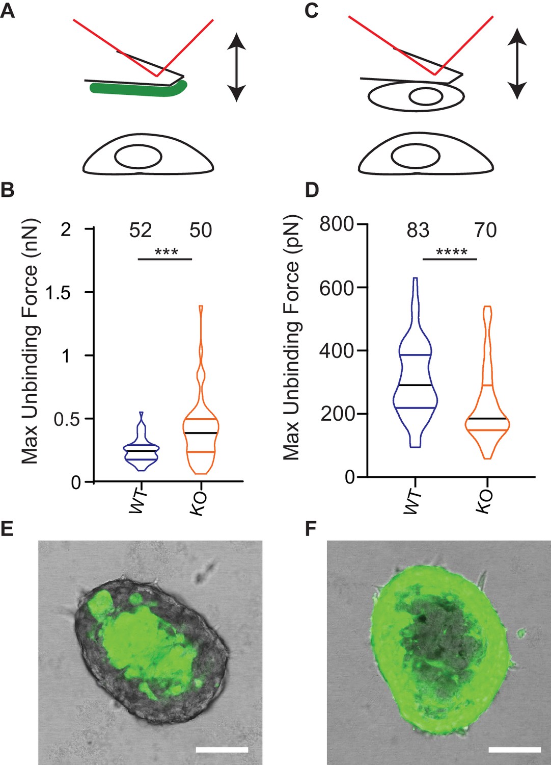
Deletion of Elkin1 modulates cell binding forces.
(A) Diagram of AFM analysis of cell-matrix unbinding forces. (B) These data demonstrated a significant increase in the maximum unbinding force to separate cells from LM511, after a 2 s contact time (Mann-Whitney U test, WT = 52, KO = 50 force-distance curves, ***p=0.001) (C) Diagram of AFM analysis of cell-cell unbinding forces (D) A significantly higher force was required for the unbinding of WM266-4 WT cells in comparison with the Elkin1-KO cells after a 2 s contact time (Mann-Whitney U test, WT = 70, KO = 83 force-distance curves, ****p<0.0001). (E–F) Representative confocal images taken from an orthogonal slice through chimeric spheroids formed over 72 hr from equal numbers of (E) WT-GFP cells and unlabelled Elkin1-KO cells or (F) unlabelled WT cells and Elkin1-KO-GFP cells. In both cases the spheroid organises with the WT cells in the core and the Elkin1-KO cells in the periphery. Scale bars = 100 µm. Similar observations made for 10 WT-GFP:Elkin-KO and 13 WT:Elkin-KO-GFP chimeric spheroids. See Figure 8—source data 1 for further details on cell binding forces. See Figure 8—figure supplement 1 for spheroid chimera rescue experiments using Elkin1 variants.
-
Figure 8—source data 1
Source data for AFM measurements of cell binding forces.
- https://cdn.elifesciences.org/articles/53308/elife-53308-fig8-data1-v4.docx
Figure 8—figure supplement 1

Overexpression of Elkin1-L210F does not rescue the partitioning phenotype in chimeric spheroids.
Representative images of chimeric spheroids formed from equal numbers of unlabelled WM266-4 Elkin1-KO cells and Elkin1-KO cells stably expressing either hsElkin1-iso3 (A, B) or hsElkin1-iso3-L210F (C,D). Cells expressing either Elkin1 variant also co-expressed GFP (coloured green in figure). At t = 0 hr post-implantation (A, C) cells had not yet partitioned. At t = 48 hr post implantation (B, D) the cells expressing hsElkin1-iso3 were more likely to be found in the core, whereas cells expressing hsElkin1-L210F were distributed throughout the spheroid. Similar observations were made in six spheroids (hsElkin1-iso3) and nine spheroids (hsElkin1-iso3-L210F) over two independent experiments.
Additional files
-
Supplementary file 1
Proteins identified in WM266-4 cells.
- https://cdn.elifesciences.org/articles/53308/elife-53308-supp1-v4.xlsx
-
Supplementary file 2
Key resources table.
- https://cdn.elifesciences.org/articles/53308/elife-53308-supp2-v4.docx
-
Transparent reporting form
- https://cdn.elifesciences.org/articles/53308/elife-53308-transrepform-v4.pdf
Download links
A two-part list of links to download the article, or parts of the article, in various formats.
Downloads (link to download the article as PDF)
Open citations (links to open the citations from this article in various online reference manager services)
Cite this article (links to download the citations from this article in formats compatible with various reference manager tools)
TMEM87a/Elkin1, a component of a novel mechanoelectrical transduction pathway, modulates melanoma adhesion and migration
eLife 9:e53308.
https://doi.org/10.7554/eLife.53308


