Computation identifies structural features that govern neuronal firing properties in slowly adapting touch receptors
- University of Virginia, United States
- Columbia University, United States
- Baylor College of Medicine, United States
Figures
Figure 1
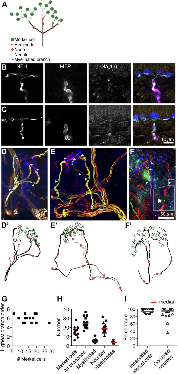
Morphometry of touch-dome afferents reveals diverse end-organ architectures.
(A) Schematic of the SAI afferent’s end organ. (B and C) SAI afferents, labeled with antibodies against Neurofilament-H (NFH; cyan) and Myelin Basic Protein (MBP; magenta), were identified by their connection to Keratin 8-positive Merkel cells (K8; blue) in touch-dome cryosections. The voltage-gated sodium channel NaV1.6 (yellow) localized to heminodes (B) and nodes of Ranvier (C). Scale bar in C (10 µm) applies to B. (D–F) Projections of touch domes labeled in whole mount. (D) NFH (red), MBP (green) and K8 (blue) labeled Merkel cells contacted by a single myelinated afferent (see also Video 1) or (E) two afferent branches whose point of convergence was not identified (see also Video 2). Arrows: examples of heminodes; arrowheads: examples of nodes of Ranvier. (F) NaV1.6 (green) identified heminodes and nodes in an NFH-positive afferent (red) innervating K8-positive Merkel cells (blue). Inset shows an expanded view of an NaV1.6-positive node. Scale bar in F (50 µm) applies to D–F’. (D’–F’) Projections of 3D reconstructions of end organs shown above: afferent (black), Merkel cells (green), heminodes (red half-circles) and nodes (red circles). (E’) A non-converging branch is marked in gray. Note that this branch is thinner than other myelinated branches. (G) The highest branching order found in each SAI afferent arbor was independent of the number of Merkel cells contacted. (H) Morphometric quantification of reconstructed touch domes innervated by single afferents. (I) More than 80% of Merkel cells were contacted by neurites and a similar proportion of terminal neurites contacted Merkel cells (N = 15 touch domes from five mice in G–I). Red lines represent median values in H and I.
Figure 2 with 1 supplement
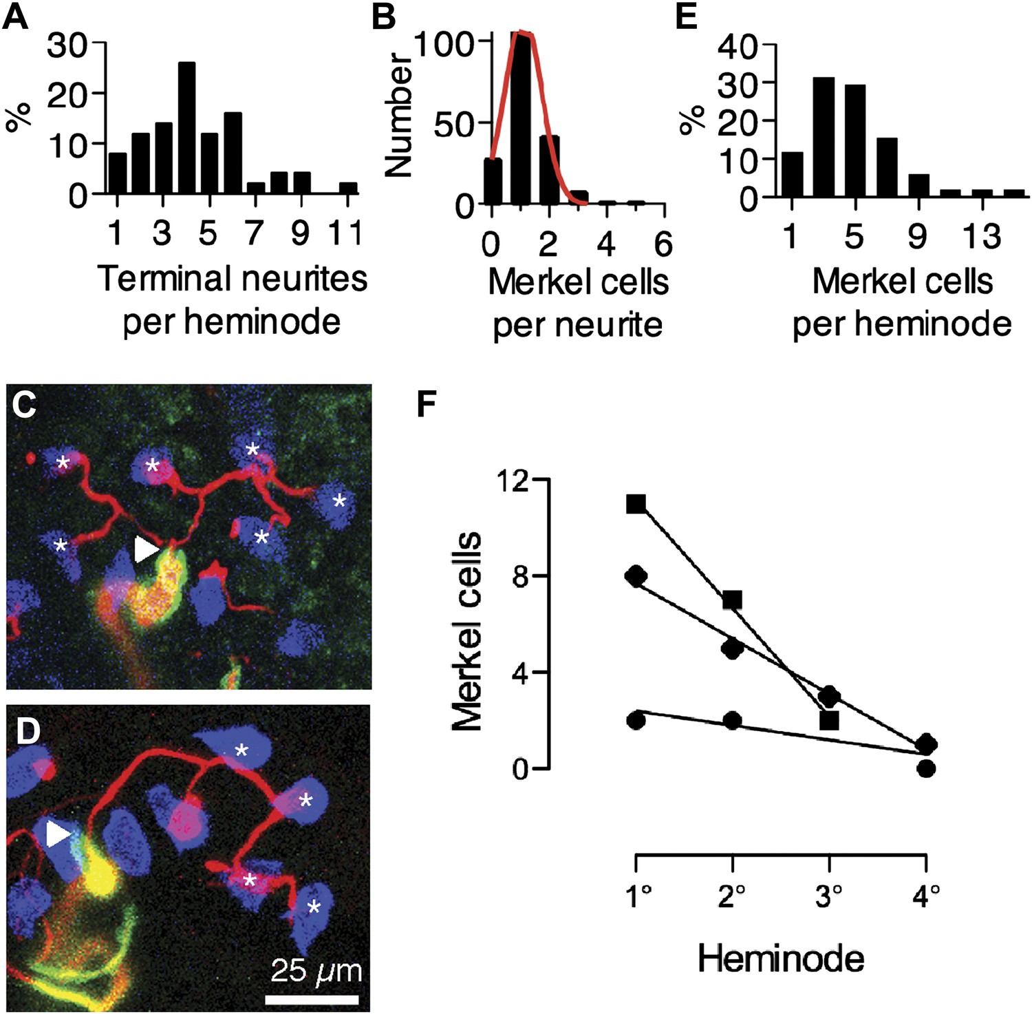
Merkel cell–neurite complexes are asymmetrically distributed between heminodes.
(A) Distribution of terminal neurites per heminode (N = 219 neurites). (B) Histogram of the number of Merkel cells contacted by each terminal neurite (N = 226 Merkel cells). Red: Gaussian fit (R2 = 0.99). (C) Confocal projection of six terminal neurites contacting individual Merkel cells (asterisks). (D) A projection of a single terminal neurite contacting a chain of four Merkel cells (asterisks). Arrowheads denote heminodes and scale bar (25 µm) applies to C and D. (E and F) The distribution of Merkel cell–neurite complexes per heminode from pooled touch-dome afferents (E; N = 51 heminodes from 15 touch domes) and within individual tactile arbors (F). In F, number of Merkel cells at each heminode from three touch domes is plotted from the largest, or primary (1°), cluster to the smallest, quaternary (4°), clusters. Representative touch domes across the skew range are shown and linear regressions are plotted (slopes = −0.6, −2.3 and −4.5, R2 = 0.6, 0.99, 1.0). See also Figure 2—figure supplement 1.
Figure 2—figure supplement 1

Skew values for each touch dome plotted vs the number of Merkel cell-neurite complexes in the arbor.
Orange symbols denote the skew values for modeled arbors in Figure 5B, which were chosen to encompass the skew range observed for most SAI arbors.
Figure 3
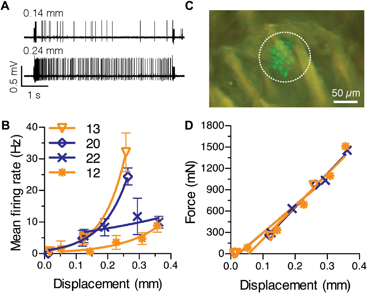
Physiological response properties vary between mouse SAI afferents.
(A) Extracellular recordings from an SAI afferent stimulated at two displacement magnitudes demonstrates the biphasic SAI response, which is characterized by high-frequency firing during the ramp phase, as well as slow adaptation and variable spike timing during the static phase. (B) Displacement–response relations from individual SAI afferents. Legend indicates the number of Merkel cells in each touch dome quantified based on GFP fluorescence. Responses from receptive fields with large end organs (blue) and small end organs (orange) are shown. Firing rates during the static phase are plotted (mean ± SD, N = 3–12 stimuli per displacement magnitude). Data were fitted with single exponentials to estimate mechanical sensitivity (κ) and threshold firing rate (Y0; R2 = 0.63–0.99). (C) Merkel cells (green) from Atoh1/nGFP transgenic mice selectively express GFP. The receptive field of the SAI afferent in A is shown (dotted line). (D) Force-displacement relations measured during the recordings shown in B. Skin mechanics were indistinguishable between these recordings.
Figure 4 with 1 supplement

Computational modeling recapitulates characteristic features of the SAI response.
(A) The network model configuration for the reconstructed SAI afferent in Figure 1D’. (B) Data flow through computational models and example outputs from each module: a finite element model (FEM) produces strain energy density (SED) at transduction units, transduction functions (Trans <# merkel cell–neurite complexes>) predict transduction currents (I(t)) and a leaky integrate-and-fire (LIF) array produces spike times. (C) The model’s predicted spike-timing variability, assessed by the distribution of normalized ISIs during static-phase responses (black bars: N = 1,591 intervals), corresponded to the skewed Gaussian distribution previously reported for mouse SAI afferents (orange bars: N = 3,348 intervals from 11 afferents; Wellnitz et al., 2010). To compare ISIs across a range of displacement magnitudes, each ISI was normalized to the mean interval for its stimulus. (D) Simulated firing rates (black symbols) from the model configuration in A were fitted to linear regressions of ramp-phase (blue dotted line: ramp acceleration = 20 mm·s−2, pink dotted line: ramp acceleration = 1143 mm·s−2) and static (orange dotted line) responses pooled from the SAI afferents shown in Figure 3B. Goodness of fit = 0.96 (fractional sum of squares). (E) Displacement–response relations from models configured with different primary cluster sizes. All configurations had 17 total transduction units and four spike initiation zones. Mean firing rates during the static phase of displacement are plotted (mean ± SD, N = 15 simulations per displacement). Displacement-response curves were compared by fitting with exponential regressions (R2 ≥ 0.99). Increasing or decreasing primary cluster size by two transduction units significantly changed the best fits (8 vs 10: p=0.004; 6 vs 8: p=0.017, extra sum-of-squares F test). Legend indicates the distribution of transduction units at spike initiation zones.
Figure 4—figure supplement 1
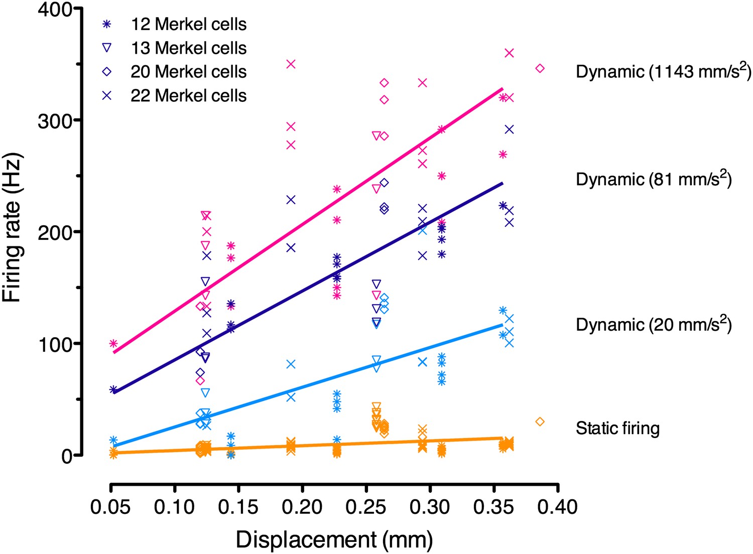
Linear regression analysis of pooled responses from the four SAI afferents in Figure 3B (denoted by symbols; N = 3–12 stimuli per displacement magnitude).
Displacements were ramped into the skin at three accelerations, which were analyzed separately (purple: 1143 mm·s−2; black: 81 mm·s−2; cyan: 20 mm·s−2). Static firing rates (orange) were pooled for regression analysis as they did not differ significantly between ramp accelerations. These regressions were used for model fitting.
Figure 5
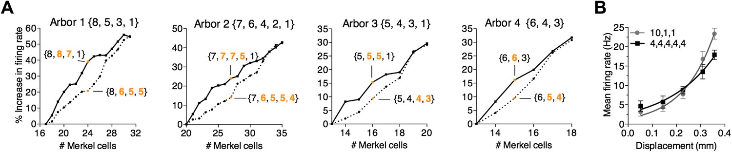
A survey of computational parameter space predicts that the number and arrangement of mechanosensory transduction units modulates SAI-afferent firing properties.
(A) Two strategies for adding transduction units to an SAI-afferent arbor were tested in four independent model end organs (Arbors 1–4). Arbor configurations differed in number of spike initiation zones (3–5) and initial end-organ sizes (13–20). Transduction units were added progressively to either secondary (solid lines) or smallest clusters (dashed lines). Orange symbols highlight examples from the two strategies after adding multiple transduction units. Example cluster arrangements are indicated in brackets. Clusters changed from the initial configuration are indicated in orange font. The percent change in firing rate from baseline configuration is plotted. (B) Comparison of displacement–response relations (mean ± SD, N = 15 stimuli per displacement magnitude) for two model configurations indicated in brackets: a skewed distribution of 12 transduction units among three spike initiation zones (gray) and an equal distribution of 20 transduction units among five spike initiation zones (black). Simulation results were fitted with single exponential equations (R2 ≥ 0.99). The mechanical sensitivity of the small end organ was predicted to be significantly greater than that of the large end organ (κ = 7.7 and 5.0, respectively, p=0.005, extra sum-of-squares F test).
Videos
Video 1
Three-dimensional reconstruction and Neurolucida tracing of the touch dome in Figure 1D, which is innervated by a single SAI afferent.
https://doi.org/10.7554/eLife.01488.004
Video 2
Three-dimensional reconstruction and Neurolucida tracing of the touch dome in Figure 1E.
This touch dome was innervated by three major branches, one of which did not converge within the imaging field. Note that this unbranched afferent is thinly myelinated and has a finer axonal diameter than typical SAI afferents.
Tables
Table 1
Effects of primary and secondary cluster size on firing rate
| Model arbor # | Merkel-cell number | Grouping 1 | Grouping 2 | ΔPrimary group | ΔSecondary group | % Firing Rate Δ |
|---|---|---|---|---|---|---|
| 1 | 17 | {6, 5, 3, 3} | {10, 5, 1, 1} | 4 | – | 39 |
| 1 | 17 | {8, 3, 3, 3} | {8, 7, 1, 1} | – | 4 | 15 |
| 2 | 20 | {6, 6, 4, 2, 2} | {9, 6, 3, 1, 1} | 3 | – | 18 |
| 2 | 20 | {7, 4, 4, 3, 2} | {7, 7, 4, 1, 1} | – | 3 | 9 |
| 3 | 13 | {4, 4, 3, 2} | {6, 4, 2, 1} | 2 | – | 12 |
| 3 | 13 | {5, 3, 3, 2} | {5, 5, 2, 1} | – | 2 | 4 |
| 4 | 13 | {5, 4, 4} | {7, 4, 2} | 2 | – | 14 |
| 4 | 13 | {6, 4, 3} | {6, 6, 1} | – | 2 | 5 |
-
Bold values indicate the group whose number was changed in the computational experiment.
Download links
A two-part list of links to download the article, or parts of the article, in various formats.
Downloads (link to download the article as PDF)
Open citations (links to open the citations from this article in various online reference manager services)
Cite this article (links to download the citations from this article in formats compatible with various reference manager tools)
Computation identifies structural features that govern neuronal firing properties in slowly adapting touch receptors
eLife 3:e01488.
https://doi.org/10.7554/eLife.01488


