Two-subunit DNA escort mechanism and inactive subunit bypass in an ultra-fast ring ATPase
- University of California, United States
- California Institute for Quantitative Biosciences, United States
- Howard Hughes Medical Institute, University of California, United States
- Lawrence Berkeley National Laboratory, United States
- Kavli Energy NanoSciences Institute at the University of California, Berkeley and the Lawrence Berkeley National Laboratory, United States
Figures
Figure 1 with 1 supplement
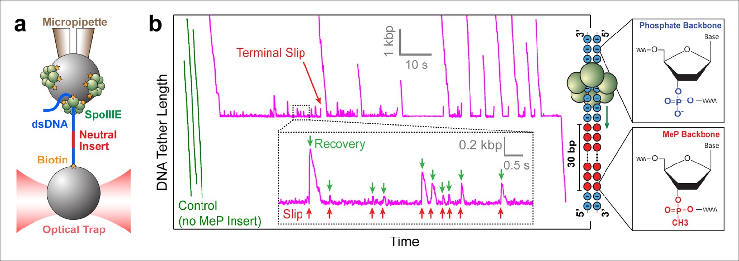
Probing SpoIIIE-DNA interactions with neutral DNA inserts.
(a) Experimental geometry of the optical tweezers assay. Neutral MeP DNA (red) was placed roughly 4 kb away from the end of the dsDNA tether (blue) that is attached to the optically trapped bead. (b) Sample traces of individual SpoIIIE motors translocating on DNA with a 30-bp dsMeP insert (magenta). Control experiments with DNA containing no MeP inserts are shown in green. Inset: detailed view of motor’s attempts to cross the neutral insert. All experiments were conducted at 3 mM ATP and a constant force of 5 pN. Traces were offset vertically to line-up the pause-like regions. Phosphate and MeP groups are represented as blue and red circles respectively.
Figure 1—figure supplement 1
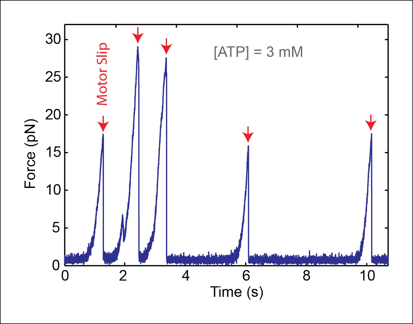
A single SpoIIIE ring translocates DNA in single-molecule experiments..
We performed control experiments in 'passive mode' where the optical trap position is fixed. As SpoIIIE translocates the DNA tether, it pulls the bead away from the trap, causing the tension in the DNA to increase. Upon reaching a certain force, SpoIIIE loses its grip on DNA and slips (red arrows), then resumes translocation from zero force. The fact that each slip occurs in a single, nearly instantaneous step indicates that a single SpoIIIE ring is translocating the DNA. Unfiltered 1-kHz data is shown.
Figure 2
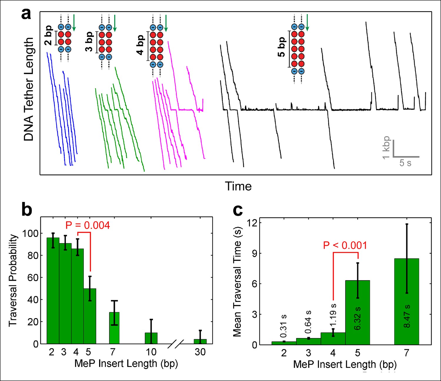
Monitoring SpoIIIE crossing of contiguous MeP inserts.
(a) Sample traces of SpoIIIE translocating on DNA with dsMeP inserts of 2 bp (blue), 3 bp (green), 4 bp (magenta), and 5 bp (black). (b) Traversal probability for dsMeP inserts of various length. Note the sharp decrease in traversal probability between 4-bp and 5-bp inserts. Error-bars represent the 68% CI estimated via bootstrapping. (c) Mean traversal time for dsMeP inserts of various length. Note the large increase in traversal time between 4-bp and 5-bp inserts. Error-bars represent the SEM. P values calculated with a two-tailed Fisher exact test.
Figure 3
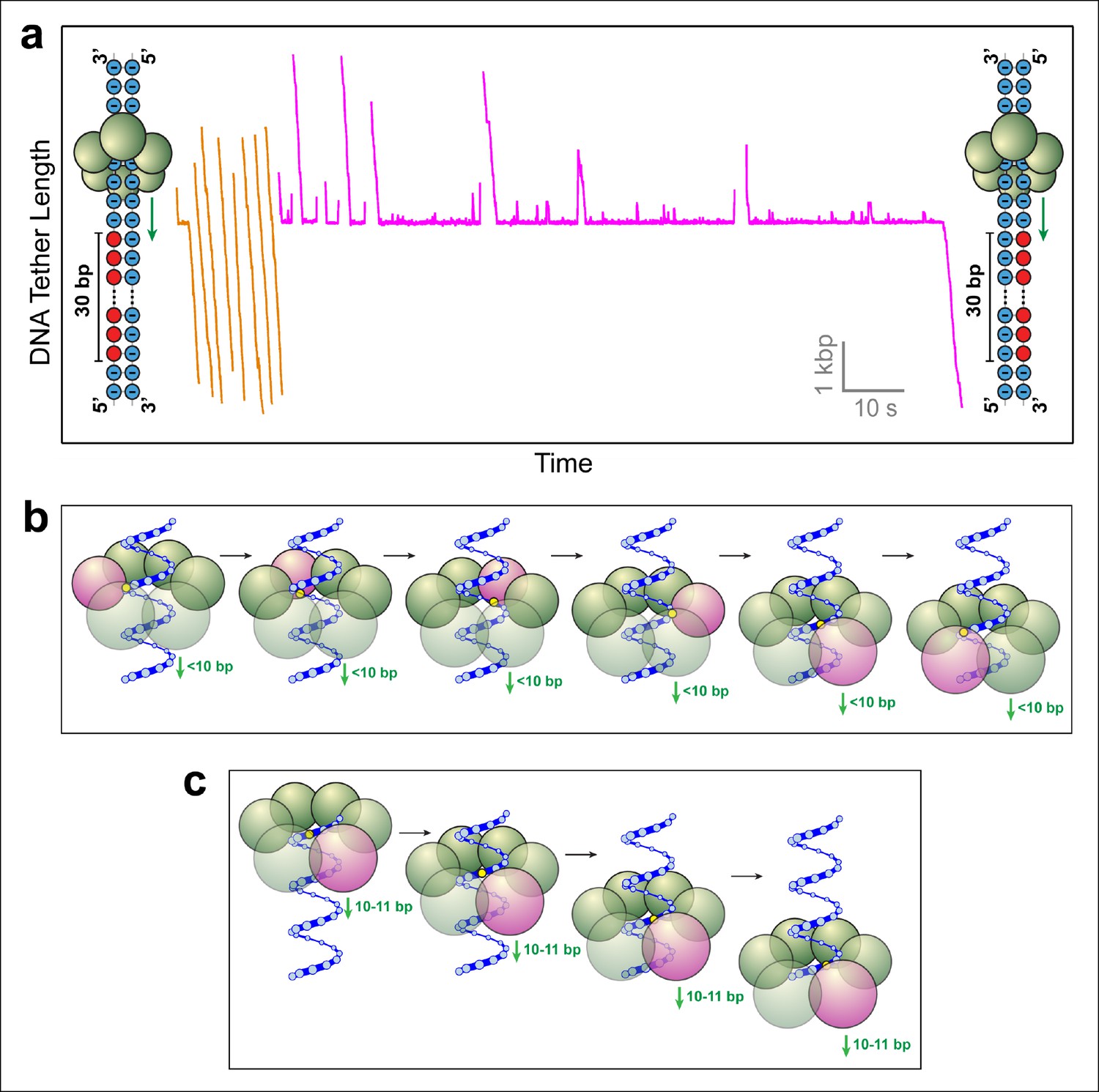
SpoIIIE favors phosphate interactions on the 5’-3’ strand in the direction of translocation.
(a) Sample traces of SpoIIIE translocating on DNA with 30 bp of neutral DNA on either the 3’-5’ strand (orange traces) or the 5’-3’ strand (magenta traces) in the direction of translocation. (b) Cartoon illustrating a hypothetical sequential model in which the DNA backbone is handed off between adjacent subunits within a hexameric ring. For clarity only one strand of dsDNA is shown. A highlighted backbone phosphate (yellow) is in contact with a motor subunit (magenta). In general, the motor step size in such a model can be anything less than 10 bp. Here we illustrate the model using a 2-bp step size. After one motor subunit (magenta) executes its power-stroke, the helical backbone of the dsDNA’s will be shifted, positioning the phosphate backbone in close proximity to the next subunit poised to fire. (c) Cartoon illustrating a hypothetical model in which a 10-bp burst enables a hexameric ring ATPase to maintain phosphate contacts on the same DNA strand. Initially, a single subunit (magenta) is contacting the phosphate backbone (yellow). After a 10 bp burst, the motor has traversed nearly a full helical turn on dsDNA, bringing the phosphate backbone back in register with the same ATPase subunit.
Figure 4
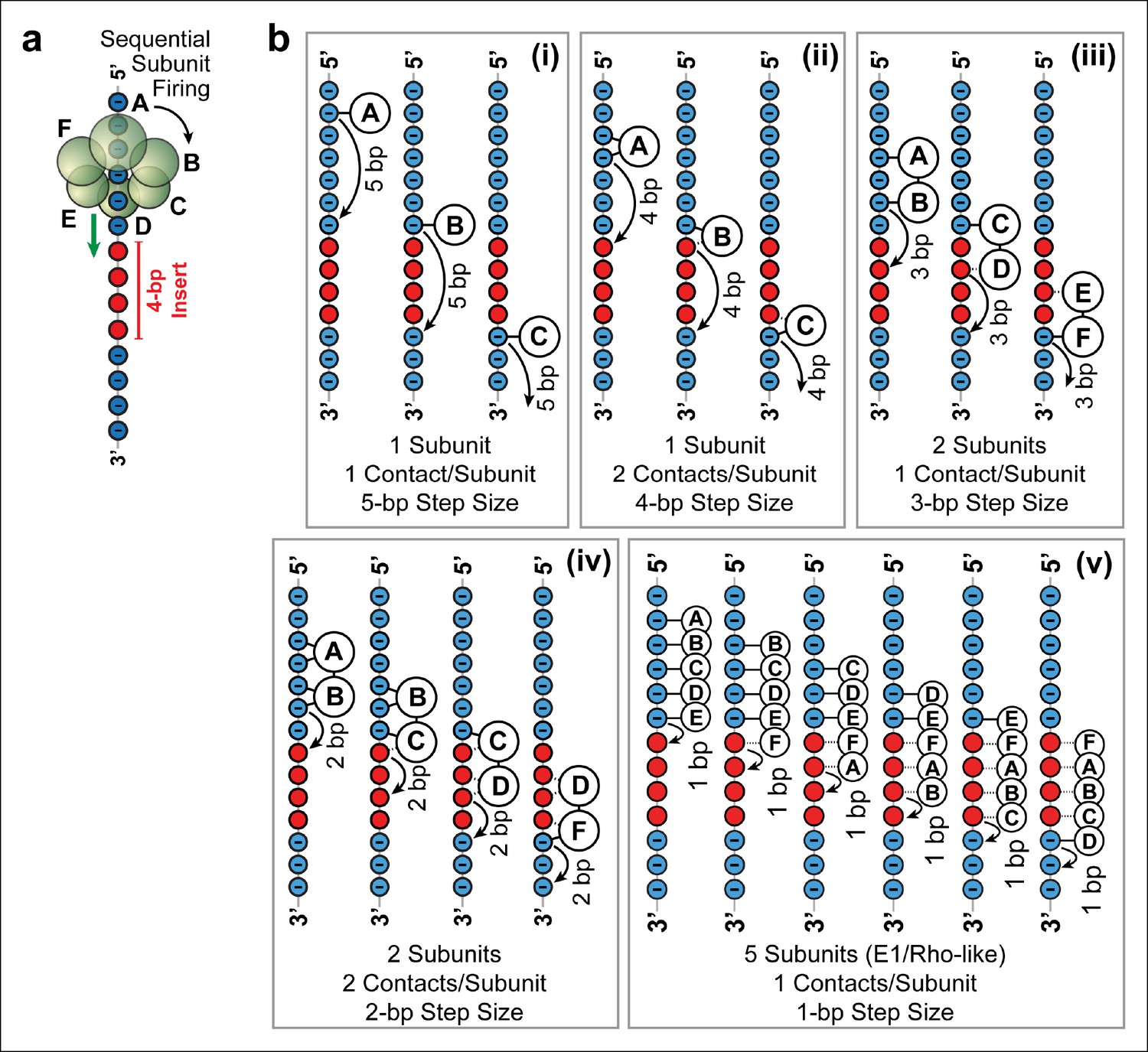
Possible SpoIIIE translocation models capable of crossing 4 bp of dsMeP.
(a) Cartoon illustrating the sequential firing of subunits A–F of SpoIIIE as it approaches a 4 bp insert of dsMeP. (b) Possible translocation models (i–v) depicting the interaction between SpoIIIE subunits (A–F) and DNA; in all models subunits fire in a sequential order (A→B→C→D→E→F→A etc). For clarity, we show only the backbone the DNA strand tracked by SpoIIIE. Phosphate and MeP groups are shown in blue and red, respectively. A solid line connecting a SpoIIIE subunit to the backbone represents a stable electrostatic interaction; a dashed line represents a disrupted interaction.
Figure 5 with 1 supplement
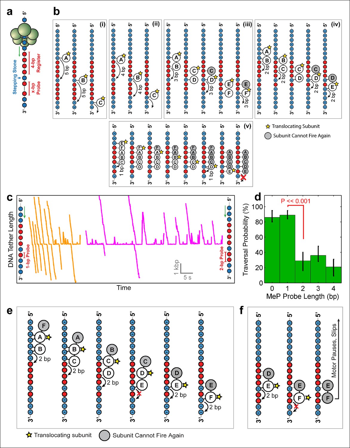
Deducing SpoIIIE’s step size using 'stepping-stone' MeP constructs.
(a) The design of 'stepping-stone' constructs. Each insert consists of a register segment with 4 bp of neutral DNA, followed by one regular DNA base ('stepping-stone'), and a probe segment with x bp of neutral DNA. For clarity, only the DNA strand tracked by SpoIIIE is shown. (b) Diagrams illustrating the longest probe segment that can be traversed by the models depicted in Figure 4b. Model (i) should traverse a probe segment of at most 4 bp, whereas model (v) cannot traverse even a probe of 1 bp. (c) Sample traces of SpoIIIE translocating on DNA with 'stepping-stone' inserts containing a 1-bp probe (orange) or a 2-bp probe (magenta). (d) Traversal probability for stepping-stone constructs with various probe lengths. Error-bars show the 68% CI estimated via bootstrapping. p values were calculated using a two-tailed Fisher exact test. (e) Diagram illustrating how model (iv) can successfully traverse a 'stepping-stone' insert with a probe of 1 bp. The star marks the subunit executing the power-stroke. Once a subunit fires, it cannot fire again (gray shading) and must eventually disengage from the DNA (subunit shown as making no interactions with DNA). (f) Diagram showing why model (iv) fails to cross a 'stepping-stone' insert with a probe of 2 bp.
Figure 5—figure supplement 1
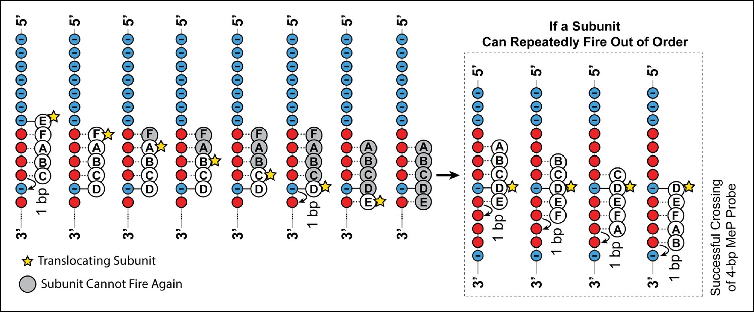
Crossing predictions of the E1/Rho-like translocation models.
Diagram illustrating two different scenarios of how the E1/Rho-like translocation model would cope with a MeP stepping stone insert. In this model subunits fire in a well-defined sequential order (firing subunit denoted by the yellow star) and move by 1 bp on DNA, whereas the remaining subunits escort the DNA during the translocation process. If the ATPase subunits have to fire in a strictly sequential order, a subunit cannot fire multiple consecutive times, or fire out of order, and is grayed out after firing. A motor operating via a strictly sequential E1/Rho-like translocation mechanism is not capable of crossing a MeP stepping stone insert with a 1-bp probe (frame 8), contrary to our observations (Figure 5c–d). If the same ATPase subunit could fire out of order several times in a row, the motor should traverse a MeP stepping stone insert with a 4-bp probe (inset), again inconsistent with our findings (Figure 5c–d).
Figure 6 with 1 supplement
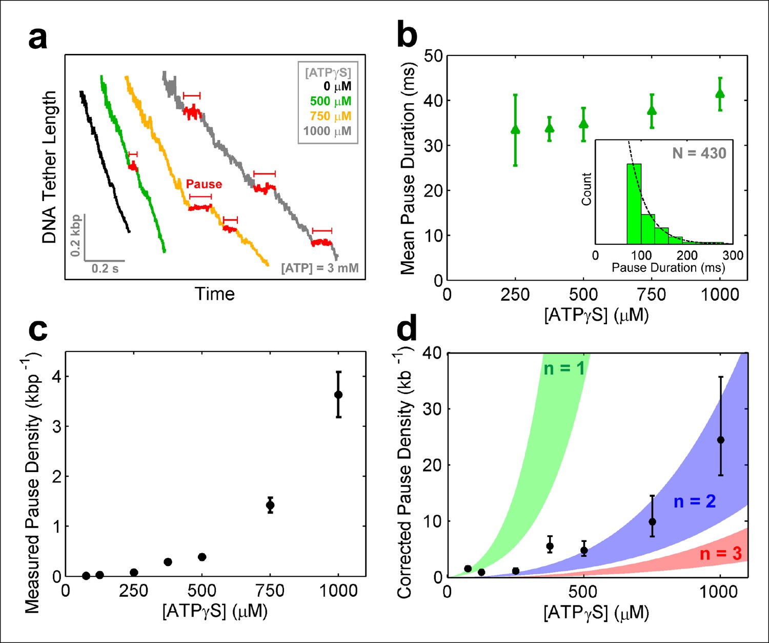
SpoIIIE pauses when two consecutive subunits are bound to ATPγS.
(a) Sample SpoIIIE traces acquired at different [ATPγS] and 3mM ATP. Pauses are highlighted in red. (b) Mean duration of the ATPγS-induced pauses extracted from fitting the pause duration distribution to an exponential. Error-bars represent the 95% CI of the fit. Insert: histogram of pause durations at 750 μM ATPγS and 3 mM ATP and the exponential fit to this distribution. (c) The density of ATPγS-induced pauses at various [ATPγS] and 3mM ATP. Error-bars represent the SEM. (d) Pause density versus [ATPγS] corrected to account for missed pauses (black symbols). Error-bars represent the SEM. The shaded regions illustrate the predictions for a sequential hydrolysis model where SpoIIIE pauses when n consecutive subunits are bound to ATPγS.
Figure 6—figure supplement 1

SpoIIIE activity inhibition with ATP analogs.
(a) Pause-free velocity versus opposing force for various [ATPγS] and 3mM ATP. Error-bars represent the SEM. (b) Degree of pause-free velocity inhibition i = 1-v ([ATPγS])/vmax versus [ATPγS] at 3 mM [ATP] and 5 pN of opposing force. The dashed curve represents the fit to the competitive inhibition model (inset) with Ki = 124 ± 20 µM. (c) Pause-free velocity versus opposing force at 3 mM [ATP] in the absence of any nucleotide analogs (black), in the presence 500 µM [ATPγS] (green), or in the presence of 500 µM [AMP-PNP] (pink). Error bars represent the SEM. (d) Pause density measured at 3 mM [ATP] and various [ATPγS] (blue symbols). Experiments were also performed with 3 mM [ATP] and 0.5 mM [AMP-PNP] (red symbol). Error bars represent the SEM. (e) Pause density versus opposing force at 3 mM [ATP] and 1 mM [ATPγS]. (f) Mean lifetime of ATPγS-induced pauses calculated from single-exponential fits to the pause duration distribution at 3 mM [ATP] and 1 mM [ATPγS]. Error bars represent the 95% CI of the fits.
Figure 7 with 1 supplement
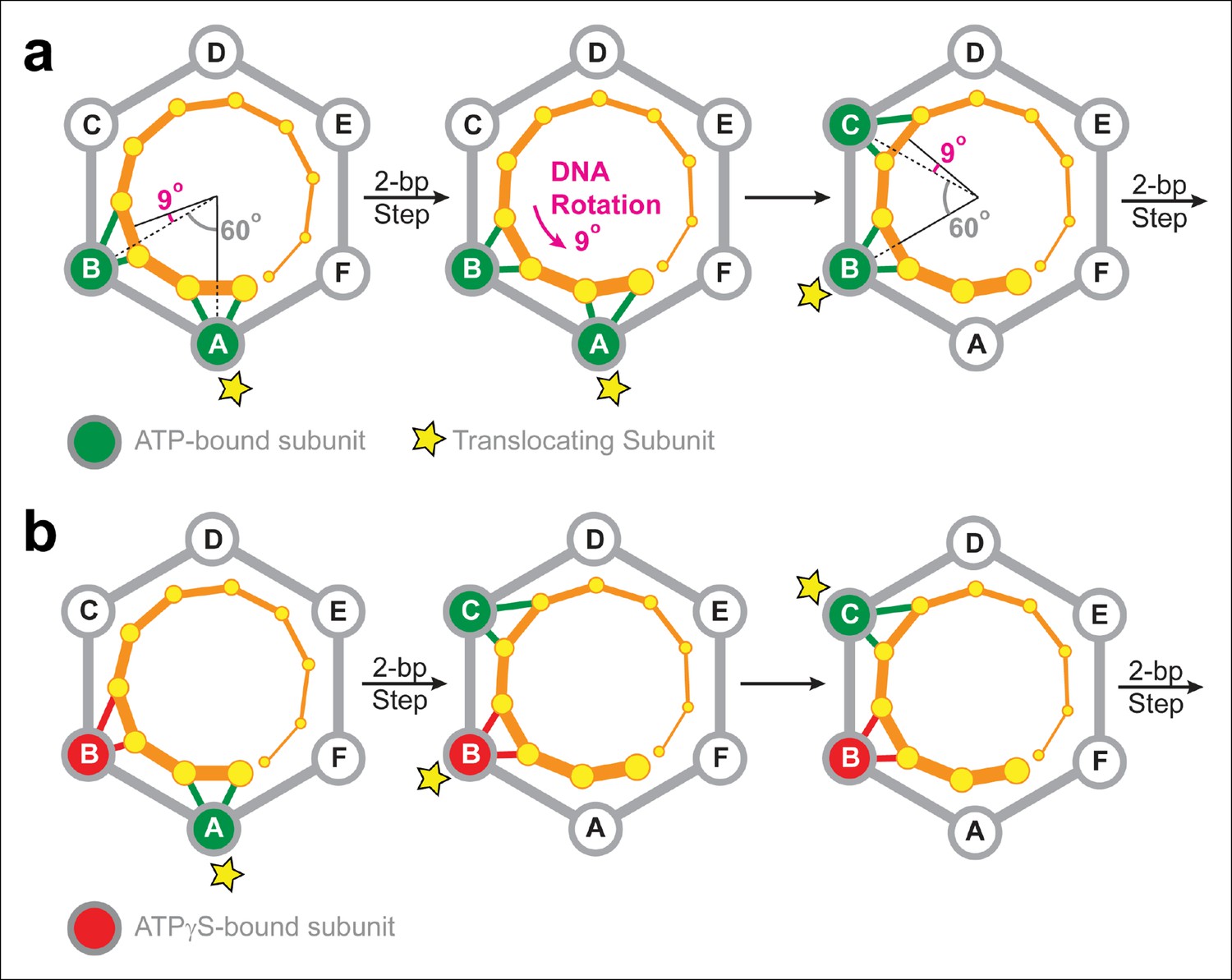
Two-subunit DNA escort model.
(a) Diagram illustrating how SpoIIIE supercoils DNA while tracking the phosphate backbone of one DNA strand. Neighboring subunits in the SpoIIIE hexamer are spaced by 60°; consecutive DNA phosphates are spaced by ∼34°; and the backbone contacts of two adjacent subunits are separated by ∼69°. After a 2-bp translocation step, a 9-degree counter-clockwise rotation of the DNA relative to the motor is needed to align the next translocating subunit and the nearest pair of backbone phosphates. (b) Diagram of the SpoIIIE hexamer illustrating how the two-subunit DNA escort model enables the motor to bypass an ATPγS-bound subunit (red). For simplicity, only one DNA strand is shown (orange). DNA is translocated out of the page, and each subunit interacts with two neighboring phosphates. The star marks the subunit slated to execute the power-stroke.
Figure 7—figure supplement 1
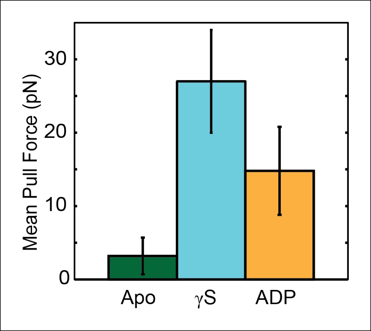
Assessing the strength of the SpoIIIE–DNA interaction in the presence of different nucleotides.
To probe the strength of the motor-DNA interaction in the presence of different nucleotides, we pulled on single SpoIIIE-DNA complexes in a nucleotide-free buffer (Apo state, green), 1mM [ATPγS] (cyan), and 1mM [ADP] (orange) and measured the mean pull force, that is, the average force at which the tether ruptured. Error bars represent the SEM.
Author response image 1

Tables
Table 1
MeP traversal statistics.
| DNA construct | Successful crossings | Failed crossings | Total traces |
|---|---|---|---|
| ssMeP modification | |||
| 30 base 3'→5' MeP | 23 | 1 | 24 |
| 30 base 5'→3' MeP | 6 | 22 | 28 |
| dsMeP Modification | |||
| 2 bp dsMeP | 21 | 1 | 22 |
| 3 bp dsMeP | 16 | 0 | 16 |
| 4 bp dsMeP | 21 | 3 | 24 |
| 5 bp dsMeP | 13 | 13 | 26 |
| 7 bp dsMeP | 3 | 9 | 12 |
| 10 bp dsMeP | 1 | 19 | 20 |
| 30 bp dsMeP | 1 | 31 | 32 |
| Length of MeP Probe Segment* | |||
| 4 bp dsMeP probe | 7 | 16 | 23 |
| 3 bp dsMeP probe | 9 | 16 | 25 |
| 2 bp dsMeP probe | 6 | 18 | 24 |
| 1 bp dsMeP probe | 33 | 4 | 37 |
-
All MeP data was gathered under 5 pN of opposing force and [ATP] = 3 mM
-
*All MeP probe segments carry a 4 bp dsMeP modification upstream of the probe
Download links
A two-part list of links to download the article, or parts of the article, in various formats.
Downloads (link to download the article as PDF)
Open citations (links to open the citations from this article in various online reference manager services)
Cite this article (links to download the citations from this article in formats compatible with various reference manager tools)
Two-subunit DNA escort mechanism and inactive subunit bypass in an ultra-fast ring ATPase
eLife 4:e09224.
https://doi.org/10.7554/eLife.09224


