Stereotyped spatial patterns of functional synaptic connectivity in the cerebellar cortex
- CNRS Université de Strasbourg, France
- Johns Hopkins University, School of Medicine, United States
Figures
Figure 1 with 2 supplements

Identification of anatomical cortical microzones by the zebrin II bands (A) Diagram of two cerebellar modules.
One module is composed of a cortical microzone (light red area), the target area of Purkinje cells (PC, red) in the cerebellar nuclei (black and white cells) and a group of olivary cells (gray) sending their climbing fibers (CF, gray line) to the cortical microzones and cerebellar nuclei. Mossy fibers (MFs, green lines) send sensorimotor information to the cerebellar nuclei and the microzones. The parallel fibers (PFs), the axon of granule cells (GCs), cross several microzones belonging to different modules. The red double arrow between the two modules illustrates intermodular communication. GoC: Golgi cell; MLI: molecular interneuron; filled triangles indicate excitatory synapses; empty triangles indicate inhibitory synapses. (B) Diagram illustrating AAV2/1-GFP or fluoro-ruby injection (green pipettes) sites in the external cuneate nucleus (ECu) and in segment L3–L5 of the spinal cord (SC). The blue double arrowhead line indicates the localization of the coronal section shown in panel C. (C) Coronal section across lobule III of the cerebellar cortex showing GFP fluorescence in MF rosettes following viral injection in the external cuneate nucleus (Ecu-MFs, green), aligned with anti-aldolase C/zebrin II (ZII, red) immunostaining. White dotted lines highlight positive zebrin II bands (P1+, P2− and b+ from the midline). (D) Upper panel, superimposed intensity plot profiles of the molecular layer (red) and granule cell layer (green) section shown in C illustrating bilateral MF projections. Upper labels, positive and negative zebrin bands. Black dotted line, midline. Lower panel, summary of MF inputs projection pattern in vermal lobule III from external cuneate (13 slices/4 animals) and spinal cord (4 slices/1 animal) compared to zebrin II bands (two positive bands: P1+, P2+ in red; and two negative bands: P1− and P2−).
Figure 1—figure supplement 1
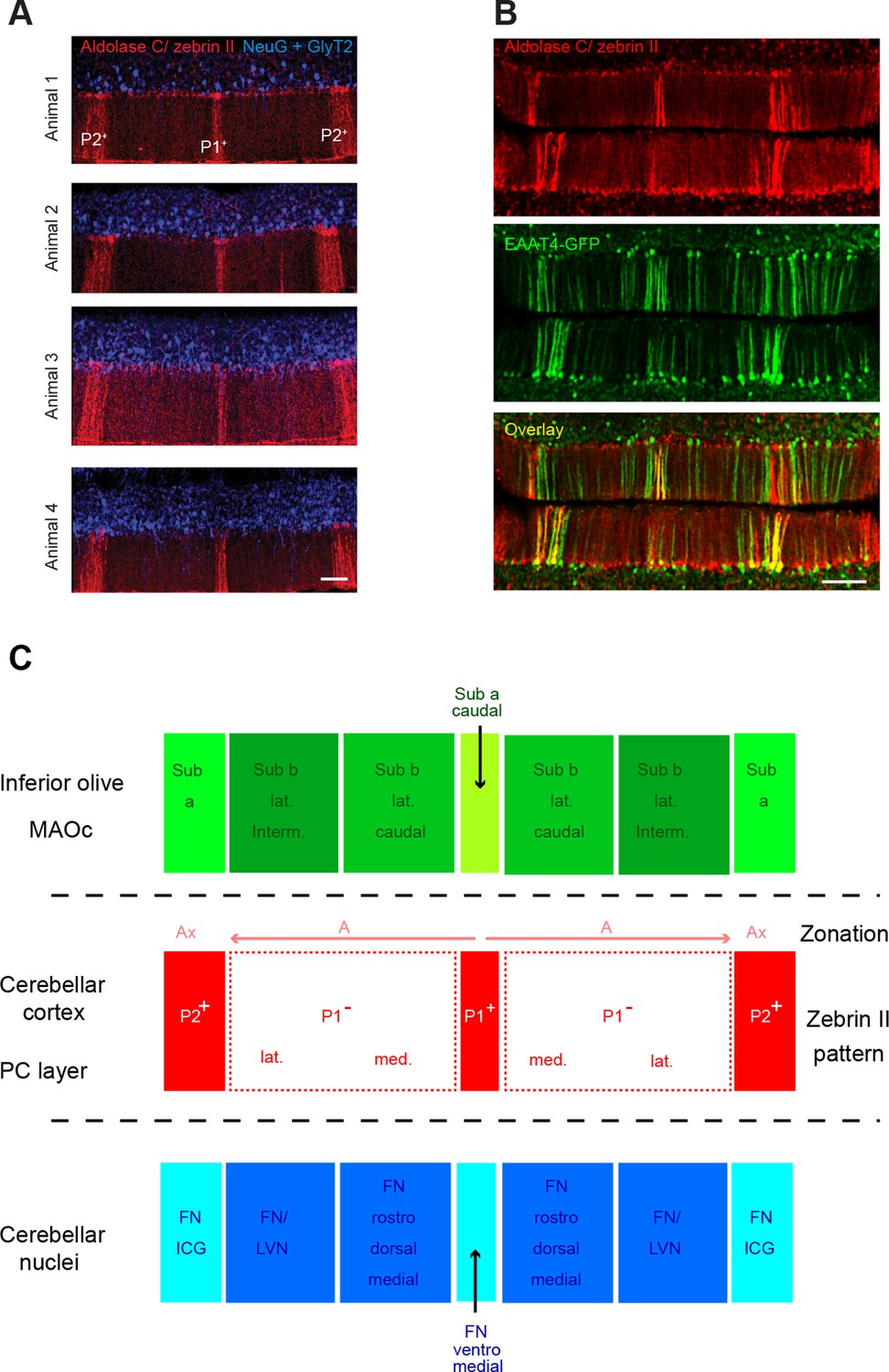
Zebrin bands as an accurate positioning tool.
(A) Immunolabeling against aldolase C/zebrin II (red), neurogranin and GlyT2 (both in blue) in the vermis of lobule IV from four different animals. Neurogranin and GlyT2 label Golgi cells (GoCs). Note the stereotyped zebrin band pattern. (B) The EAAT4-GFP transgenic mice express GFP in zebrin II-positive bands. Top: immunolabeling for aldolase C/zebrin II (red) in a slice from an EAAT4-GFP mouse. Middle: GFP fluorescence in the same slice. Bottom: overlay. Scale bar, 100 μm. (C) Diagram illustrating the topographical organization of climbing fiber (CF) inputs to the cerebellar cortex (green boxes refer to inferior olive subregions) and the partial match with the zebrin band patterning (red boxes refer to zebrin bands) and the cortico-nuclear projection to cerebellar nuclei (blue boxes refer to nuclear subregions). The olivo-cortico-nuclear loop defines the cerebellar module. Note that P1− is split onto two subregions. The array of CF projection in the cerebellar cortex and the cortico-nuclear projections define the microzone. MAOc: caudal medial accessory olive; Sub a: subnucleus a of the MAOc; Sub b lat. interm.: intermediate part of the lateral subnucleus b of the MAOc; Sub b lat. caudal: caudal part of the lateral subnucleus b of the MAOc; Sub a caudal: caudal part of subnucleus a of the MAOc. Ax and A zones refer to the zonal nomenclature of the olivo-cortical pathway (Voogd, 1967). FN/ICG: fastigial nucleus and interstitial cell group; FN/LVN: fastigial nucleus and lateral vestibular nucleus. Adapted from Sugihara, 2011 and Voogd and Ruigrok, 2004.
Figure 1—figure supplement 2
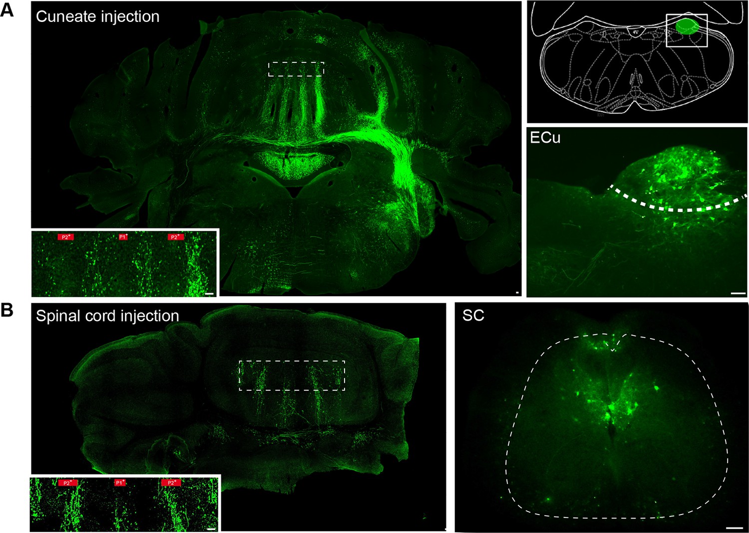
Mossy fiber projections from the external cuneate nucleus and spinal cord (segment L3-L5).
(A) Section from the cerebellum and the brainstem after AAV2/1 injection of viruses into the external cuneate nucleus. Inset: mossy fiber rosettes in lobule III. Zebrin band boundaries are shown in red. Right panel: diagram illustrating the position of the external cuneate injections (ECu). Bottom right: example of injection site in the external cuneate nucleus and infected neurons. (B) Section from the cerebellum after injection of AAV2/1 viruses into the spinal cord. Inset: mossy fiber rosettes in lobule III. Zebrin band boundaries are shown in red. Right: injection site and infected neurons in the spinal cord (SC) (see Materials and methods).
Figure 2 with 2 supplements
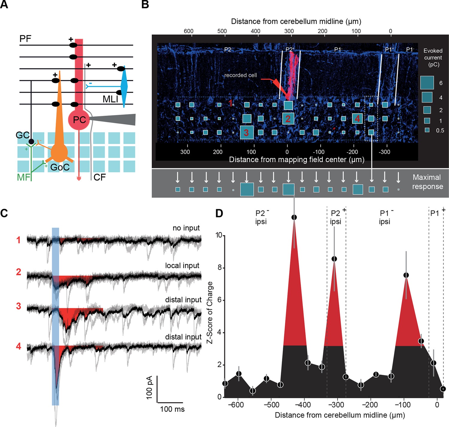
Granule cell input patterns to Purkinje cells reveal hotspots of connectivity.
(A) Experimental design and simplified diagram of the cortical microcircuit. Purkinje cell (PC) synaptic inputs were recorded. Photorelease of RuBi-glutamate at multiple locations of the granule cell (GC) layer (blue squares) mimics GC (black) activation by mossy fibers (MFs; green). GCs contact PCs, Golgi cells (GoCs; orange) and molecular interneurons (MLIs; blue) along the mediolateral axis. Inhibition is blocked and climbing fibers (CFs) are not activated. PF: parallel fibers. (B) Example of a PC (red) recorded in an EAAT4-GFP acute cerebellar slice and filled with biocytin. The recorded cell was reconstructed and located using both GFP expression (not shown) and aldolase C immunolabeling (blue). The PC in this example is located in the P2+ zebrin band. Blue squares indicate uncaging sites. The size of the square is proportional to the synaptic charge of the evoked current. Mediolateral response is given by the strongest response at all depths of the GC layer (i.e. maximal response in the white dotted box). Maximal responses along the mediolateral axis are reported in the gray area and define the connectivity pattern. The blue dashed box indicates the width of the photostimulation field. Please note the two scales: at the bottom is the distance from the recorded cell, while at the top is the distance to the midline. (C) Examples of evoked currents, from panel B. The blue bar indicates uncaging duration. The red area indicates the measured charge (window = 200 ms). (D) The connectivity pattern was expressed as the Z-score of charge, as a function of the distance to the cerebellar midline. The significance threshold was defined at Z = 3.09. Red areas are considered as functionally connected, while black areas indicate silent sites. Error bars illustrate the median from five mappings.
Figure 2—figure supplement 1
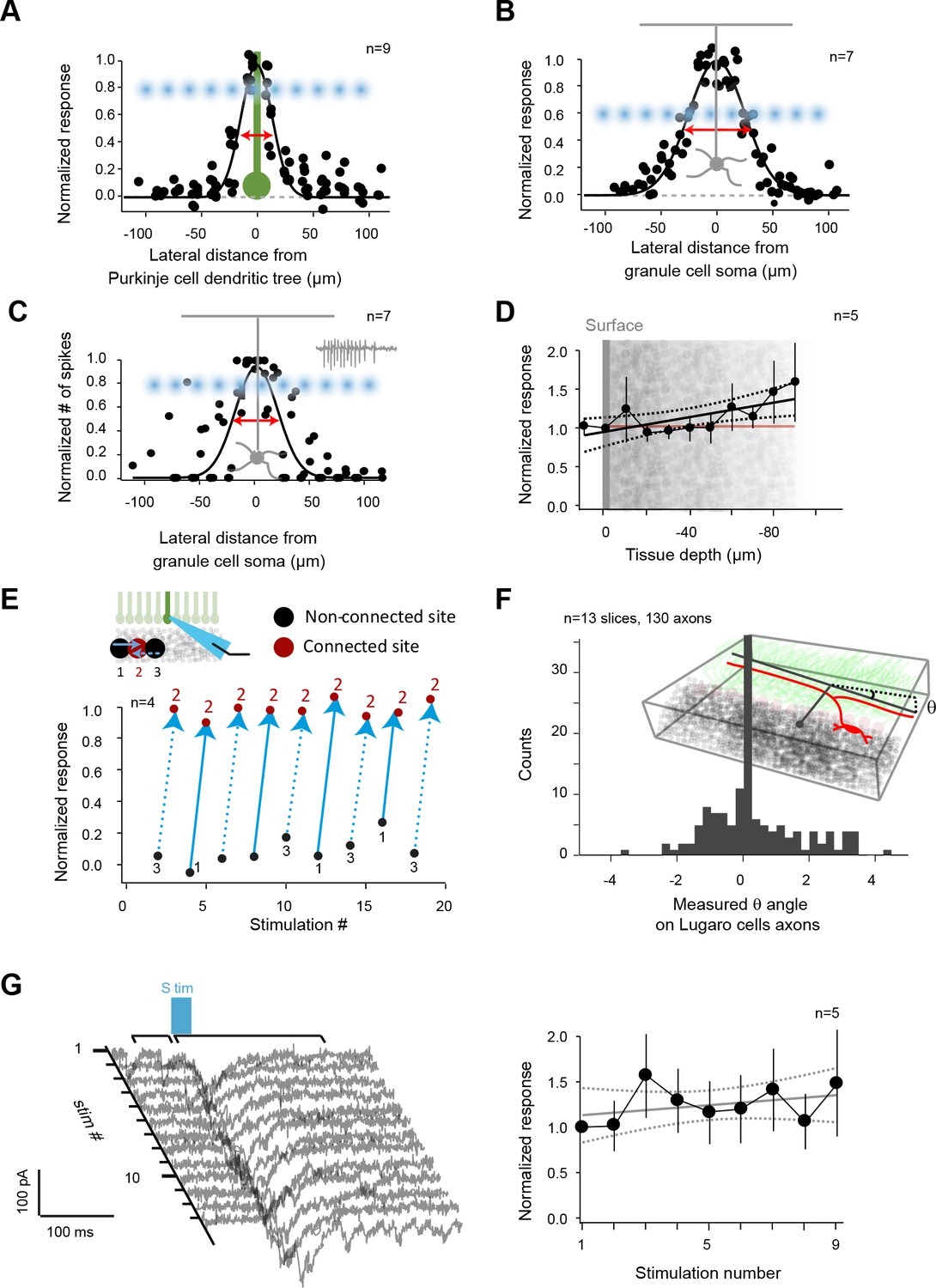
Controls for photostimulation.
(A) Normalized direct current extent in Purkinje cells (PCs) when the spot of illumination (blue dots) is moved through PC dendrites (green); illumination step: 20 μm. (B) Normalized direct current extent in granule cells (GCs) when the spot of illumination is moved through GC dendrites (step: 20 μm). (C) Normalized number of spikes elicited in GCs when the spot of illumination is moved through GC dendrites (step: 20 μm). (D) Normalized direct current response in GCs as a function of focal plane depth in slices. (E) Evaluation of independence between neighboring sites. Site 2 evoked a current in a recorded PC, but not sites 1 or 3, although they are direct neighbors. All three sites are alternatively stimulated to test for a possible spread of glutamate between sites or desensitization of glutamate receptors on site 2. (F) Distal silent sites might be due to a tilt in the slice. Slice angle was verified using Lugaro cell axons that parallel GC axons in Glyt2-GFP mice in order to rule out this hypothesis. (G) Left panel: a responding site was repetitively photostimulated to test the stability of recorded responses throughout mappings. Right panel: measured synaptic charge versus time.
Figure 2—figure supplement 2
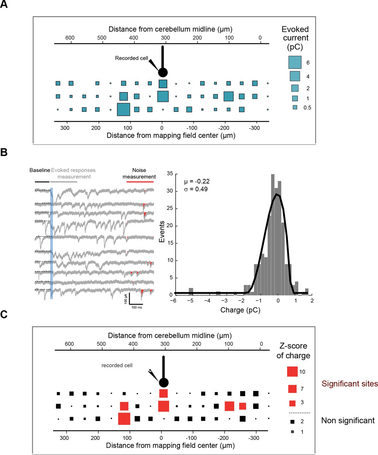
Z-score representation of the granule cell input map in one recorded cell.
(A) Initial connectivity maps were built by determining the synaptic charge elicited by granule cells at a given site. (B) In each trial, light-evoked responses (at 200 ms) and noise (at 800 ms) were measured and a histogram of the noise was built for each cell. The mean and standard deviation of the noise were determined and used to calculate the Z-score at each site (C) using the following equation: Z-score = (mean of synaptic charge at a given site − mean of noise distribution in the cell)/standard deviation of the distribution of noise. A Z-score of 3.09, corresponding to a significance level of 0.001, was chosen to define significant and silent sites.
Figure 3
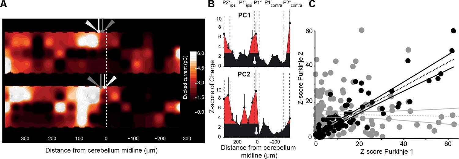
Neighboring Purkinje cells share similar granule cell input patterns.
Two neighboring Purkinje cells (PCs) were simultaneously recorded and RuBi-glutamate was systematically uncaged. (A) Map of the recorded synaptic charge measured in PC1 (white cell, top) and PC2 (white cell, bottom). Most of the responding and silent sites were observed at the same location or close by, although a few differences can be observed. (B) Corresponding mediolateral granule cell (GC) connectivity pattern to PC1 (top panel) and PC2 (bottom panel) expressed as a Z-score of the synaptic charge. PC positions are indicated in white. (C) Site by site correlation of GC connectivity patterns between neighboring PC pairs (black dots, r = 0.74 ± 0.14; n = 8 pairs). Shuffled pairs showed no correlation (gray dots, r = 0.02 ± 0.09).
Figure 4
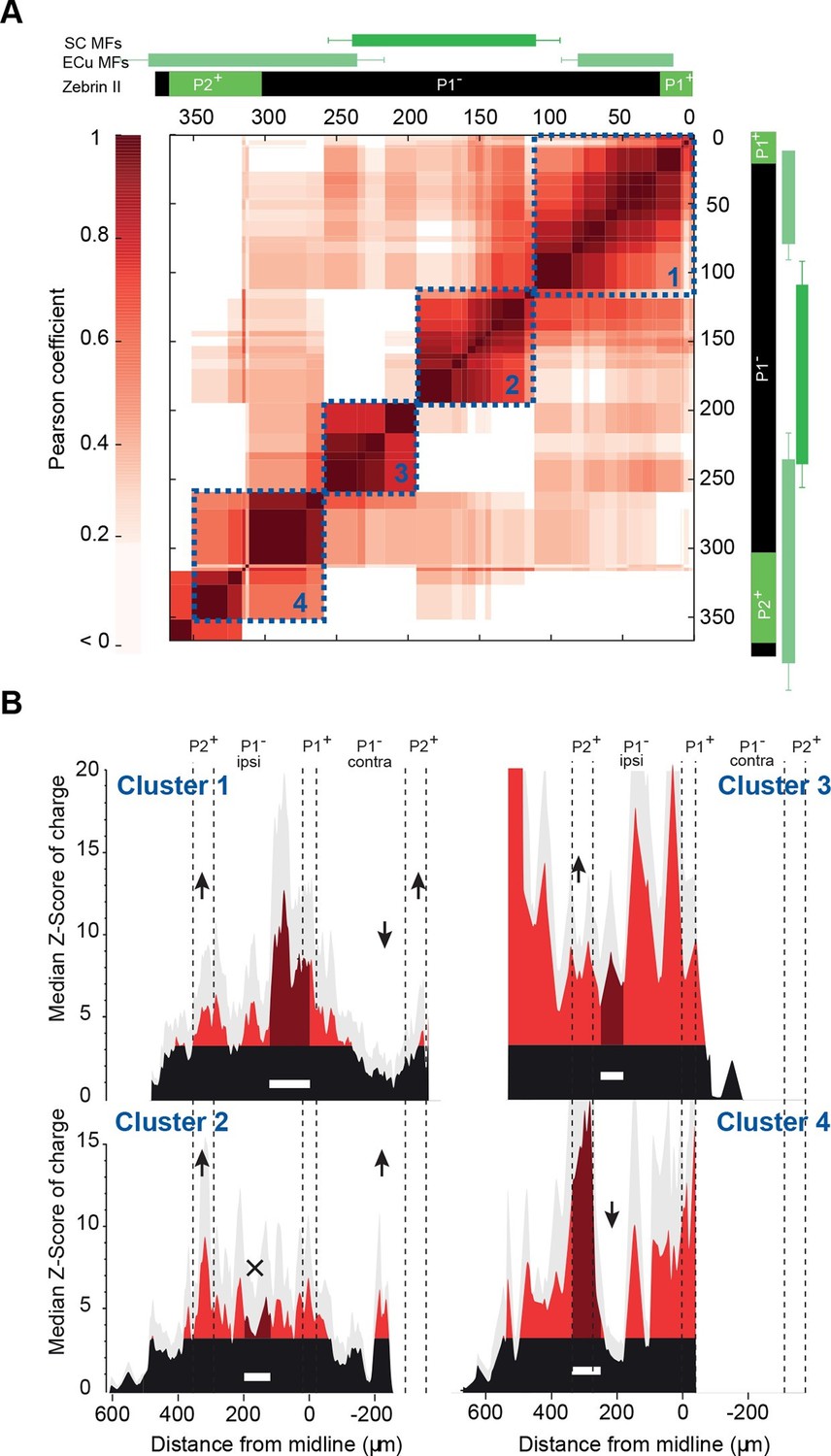
Granule cell input patterns to Purkinje cells from different animals define stereotyped clusters.
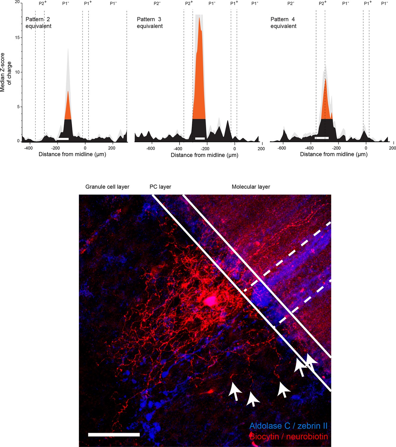
(A) Correlation matrix of groups of neighboring Purkinje cells (PCs; N = 49 cells in 18 animals). Each group corresponds to the median granule cell (GC) input pattern of PCs located within a 100 µm window. Two consecutive groups are shifted by 10 µm. The x/y axes represent the center of each median pattern. All median patterns were compared to each other, and correlation was estimated using the Pearson coefficient. Four clusters of contiguous, correlated group of cells were identified using a co-clustering algorithm (blue dotted boxes, numbered 1 to 4 from the midline to P2+). Zebrin II bands, external cuneate mossy fiber input (ECu MFs) and spinal cord MF input (SC MFs) locations are indicated in green, for comparison. (B) Median GC input patterns to the four clusters of PCs identified in A. The PC cluster position is represented as a white bar. Black: non-connected areas, Z-score < 3.09; red: significant connections, Z-score > 3.09. Error bars are in light gray. Local GC inputs (dark red) were usually observed, although weak for PCs belonging to cluster 2 (see black cross). Distal hotspots mentioned in the main text are indicated with upwards arrows. Note the systematic hotspot in P2+. Silent regions mentioned in the main text are indicated with downwards arrows.
Figure 5 with 1 supplement
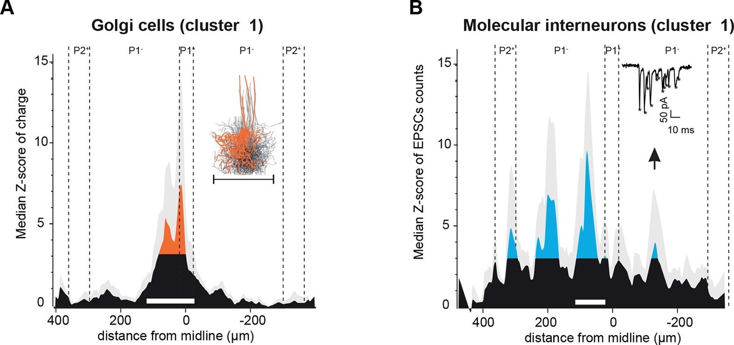
Spatial organization of granule cell (GC) input patterns to molecular interneurons and Golgi cells is distinct from GC input maps to Purkinje cells.
(A) Median granule cell (GC) input pattern to Golgi cells (GoCs; Z-score of charge) for GoCs located at the same location as Purkinje cells (PCs) from cluster 1. Black: Z-score <3.09, orange: Z-score >3.09. Error bars are in light gray. Inset: overlay of all 3D-reconstructed GoCs, showing the extension of the axonal plexus, that is, the maximal region in which GoCs could inhibit GCs (same scale as the median pattern). (B) Median GC input pattern to molecular interneurons (MLIs; Z-score of number of excitatory post-synaptic currents, EPSCs) at the same position as PCs from cluster 1. The upward arrow indicates a hotspot of GCs contacting MLIs located in the cluster 1 region, but not PCs. Inset: example of EPSCs recorded following photostimulation. Stars indicate detected EPSCs.
Figure 5—figure supplement 1
Spatial organization of granule cell input patterns to Golgi cells recorded in the area of cluster 2,3 and 4 for Purkinje cells.
Upper panel: histogram of the median Z-score for Golgi cells (GoCs) recorded in clusters 2, 3 and 4 of Purkinje cells (PCs). Lower panel: reconstruction of GoC recorded in P1− close to the P1+ boundary. Note that the axon crosses two zebrin band boundaries. Scale bar, 50 μm.
Figure 6 with 1 supplement
Tunable maps of granule cell inputs to Purkinje cells.
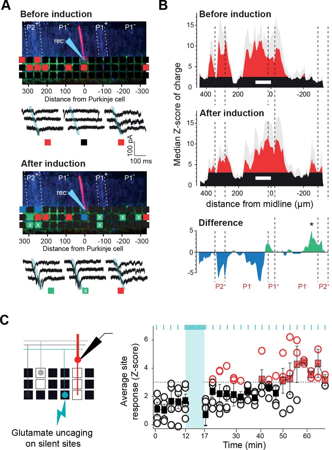
(A) Photostimulation grid superimposed on a reconstructed slice before (top) and after (bottom) the long-term synaptic plasticity induction protocol (300 stimulations at 1 Hz). The stimulation pipette was positioned in the molecular layer far from the recorded Purkinje cell (PC). Zebrin II bands were confirmed by anti-aldolase C immunolabeling (blue) and are highlighted by a white dotted line. Recorded PCs are shown in red. Connected sites are in red, silent sites in black, depressed sites in blue, and potentiated sites in green. Awaken sites are indicated with a white cross. Traces illustrate examples of synaptic currents recorded in three sites showing different plasticity (same color code). (B) Median granule cell (GC) input patterns to PCs were computed before (top panel) and after the plasticity induction protocol (middle panel) for a group of PCs from cluster 1 (n = 7). A difference between GC input patterns (bottom panel) identified a newly connected region. (C) Silent sites can be specifically awakened. Silent sites were identified in an initial map and RuBi-glutamate was uncaged repetitively (one flash every 3 s for 5 min, blue bar) at these sites. Right panel, time course of evoked responses before and after induction (blue ticks indicates photostimulations). Individual responses (n = 5 cells) are indicated as circles. Average responses are indicated by squares. Non-detectable connections are in black, while significant connections are in red.
Figure 6—figure supplement 1
Tunable maps of granule cell inputs to Purkinje cells.
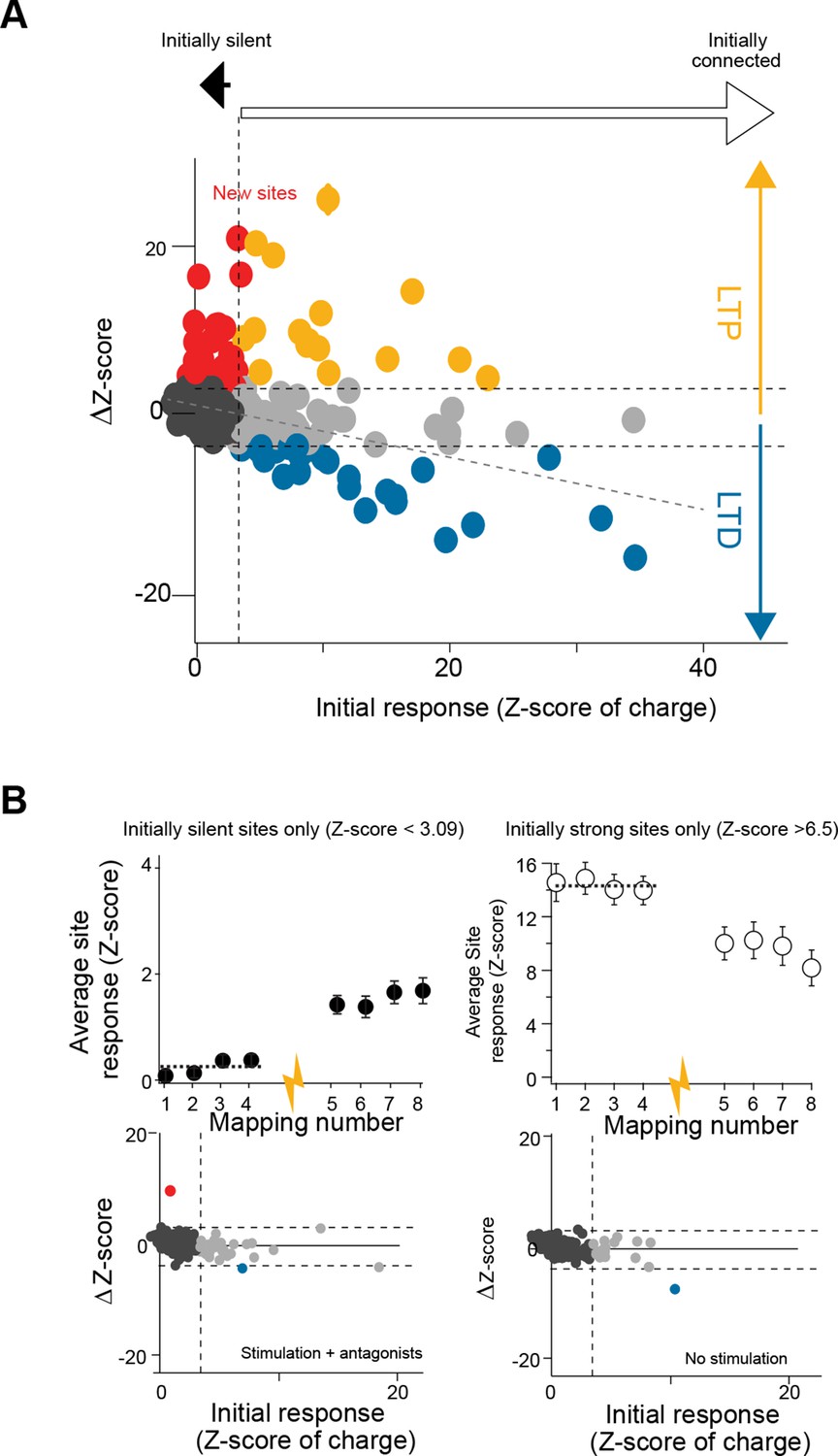
(A) Variation of granule cell (GC) synaptic charge (in ΔZ-score) per site plotted against the initial Z-score of synaptic charge (n = 8 cells). Linear regression fit (gray dotted line) illustrates the correlation between the initial response and the post-induction response. (B) Top left: time course of the averaged Z-score of synaptic charge for silent GC sites (Z-score < 3.09) before and after the induction protocol (yellow arrow). Top right: time course of the averaged Z-score of synaptic charge for strongly connected sites (Z-score > 6.5). Bottom left: same experiment as in (A), with antagonists in the bath (n = 5 cells; see Experimental procedures). Bottom right: same experiment as in (A), but with no stimulation (n = 7 cells).
Figure 7 with 1 supplement
Summary.
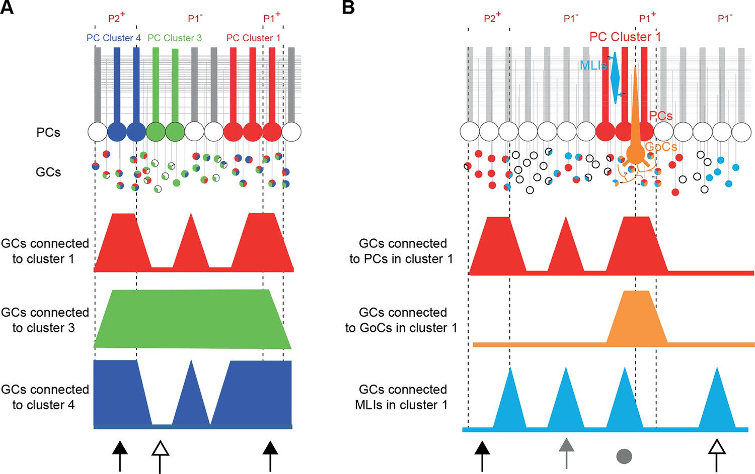
(A) Simplified diagram of granule cell (GC) input patterns to three Purkinje cell (PC) clusters. Zebrin bands are indicated with dotted lines. GC color indicates its postsynaptic target while white indicates either no target or an unknown target. Contiguous PCs display similar input patterns and each PC cluster presents a stereotyped input pattern. In the anterior vermis of lobule III/IV, some regions of the GC layer project to all recorded PCs (black arrows, for example in ipsilateral P2+ or P1+), while others can target a single PC cluster (white arrow). (B) Within a given microzone, the different cell types do not show the same GC input pattern. In cluster 1, PCs and molecular interneurons (MLIs) are sometimes contacted by GCs from the same region (either distal GCs, gray arrow, or local GCs, gray circle), while some groups of GCs contact either PCs (black arrow) or MLIs (white arrow). GoCs are mainly contacted by local inputs (gray circle) and implement local feedback inhibition.
Figure 7—figure supplement 1
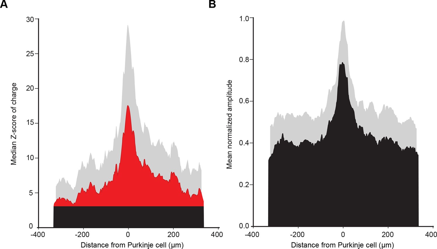
Mean histogram of normalized amplitude of granule cell inputs aligned on PC soma (see Discussion).
(A) To test how cell position can affect the median granule cell (GC) input patterns, we centered all recorded Purkinje cells (PCs) and calculated the median Z-score as previously described. Note the absence of a secondary peak. (B) Centered, normalized representation of the mean amplitude using our dataset shows results similar to those in a previous study (Walter et al., 2009)
Download links
A two-part list of links to download the article, or parts of the article, in various formats.
Downloads (link to download the article as PDF)
Open citations (links to open the citations from this article in various online reference manager services)
Cite this article (links to download the citations from this article in formats compatible with various reference manager tools)
Stereotyped spatial patterns of functional synaptic connectivity in the cerebellar cortex
eLife 5:e09862.
https://doi.org/10.7554/eLife.09862


