Autoinhibition of ankyrin-B/G membrane target bindings by intrinsically disordered segments from the tail regions
- Hong Kong University of Science and Technology, China
- University of Science and Technology of China, Anhui, China
- South University of Science and Technology of China, China
Figures
Figure 1
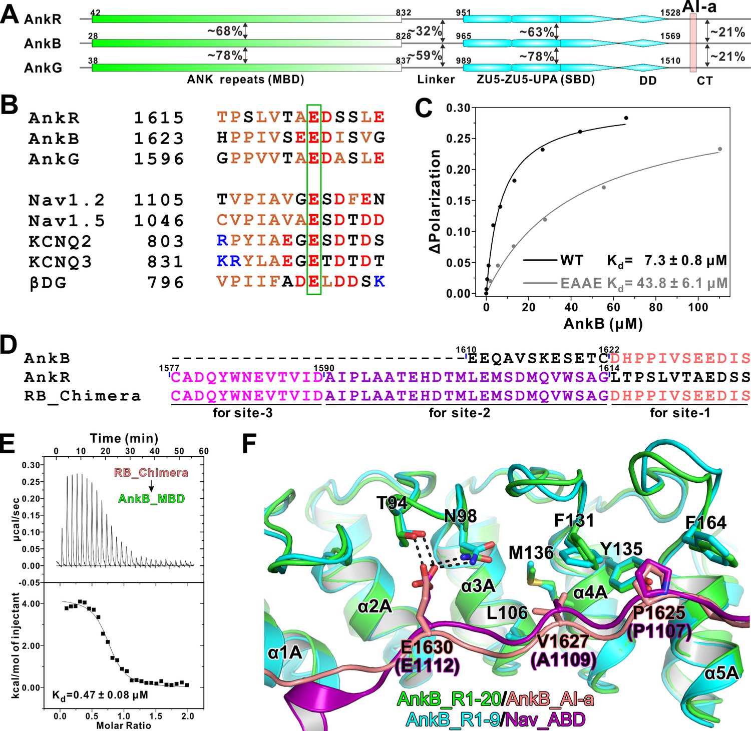
Biochemical and structural characterization of the AI-a/MBD interaction.
(A) Schematic diagram showing the domain organizations of AnkR/B/G and their amino acid sequence identities. (B) Amino acid sequence alignments of AI-a from AnkB/G with several MBD ‘site-1’ binding sequences from AnkR CT or other targets. The critical Glu residues are highlighted with a green box. (C) Fluorescence polarization-based measurement of the binding affinity between AnkB_AI-a and AnkB_MBD or its R1 charge reversal mutant (‘EAAE’). (D) The design of AnkR/B_Chimera construct for crystallization. The AnkB_AI-a sequence (colored in salmon) was fused to the C-terminus of ‘site-2, 3’ binding AnkR_CT (colored in purple and magenta respectively). (E) ITC result showing the strong interaction between AnkR/B_Chimera and MBD. (F) Structural comparison of the MBD ‘site-1’ bindings of AnkB_AI-a (colored in green and salmon) and Nav_ABD (colored in cyan and purple) showing that the two bindings essentially share the same mode. Residues critical for the interaction were highlighted with stick models. Hydrogen bonds were indicated with dashed lines (the same labeling method is used throughout the manuscript for all structural figures).
Figure 2
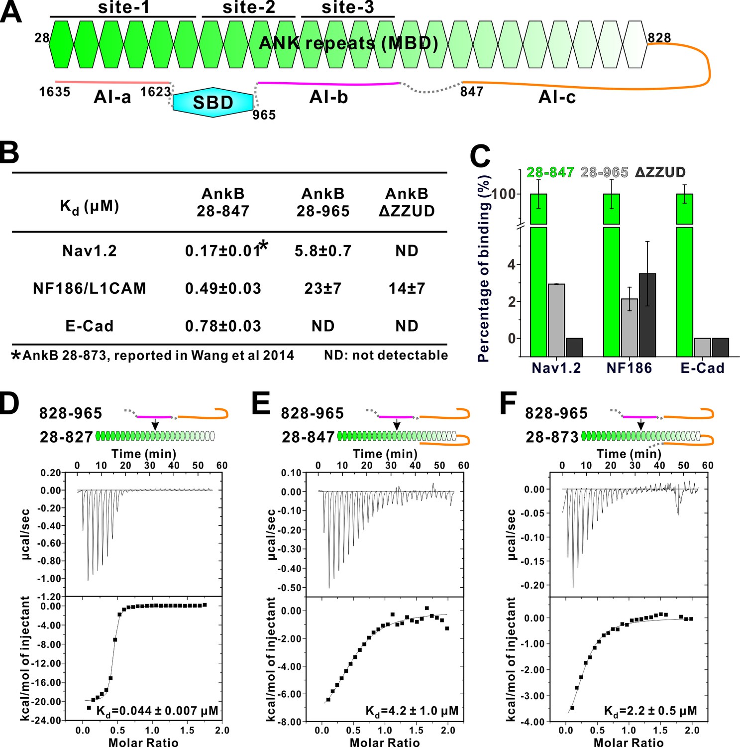
Two discrete segments in the AnkB linker region bind to MBD and inhibit its target binding.
(A) Schematic diagram showing the three autoinhibitory segments (AI-a, b, c) located at the linker and CT regions of AnkB. (B) ITC derived binding affinities showing that including longer linker region or the AI-a segment to the AnkB MBD weakened its bindings to targets including Nav1.2, NF186/L1CAM, and E-cadherin. (C) Bar graph showing the levels of target binding decreases resulted by the autoinhibitory segments based on the binding data in Panel B. (D–F) ITC profiles showing direct interactions between the entire linker region of AnkB and different versions of AnkB MBD (D: 28–827, no linker, measured in buffer containing 500 mM NaCl due to poor quality of this protein in 100 mM NaCl buffer; E: 28–847, short linker roughly comparable to the AnkR_C12 structure; F: 28–873, longer linker containing the entire AI-c).
Figure 3
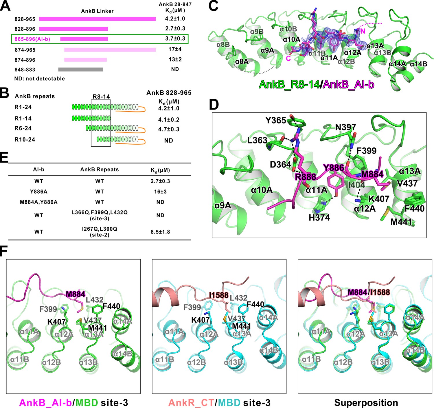
Interaction between AnkB_AI-b and AnkB_MBD.
(A) ITC-based mapping of the AnkB AI-b region. The minimal region of AI-b is indicated with a green box. The fragments with weakened or complete-loss of binding to MBD were shown in pink and grey bars, respectively. ‘ND’ represents no detectable binding in the ITC measurement and is used throughout the manuscript. (B) Similar mapping of the minimal ANK repeats responsible for AI-b binding. The repeats used for crystallization (R8-14) are highlighted with a black box. (C) The overall structure and an omit map showing the binding of AnkB_AI-b to AnkB_R8-14. The Fo-Fc density map was generated by deleting the AI-b part from the final model and contoured at 3.0 σ. The AI-b fitting the electron density is displayed in the stick model. (D) Detailed interactions between AnkB_AI-b and AnkB_MBD. The side chains or main chains of the residues involved in the interactions are highlighted in the stick model. Charge-charge and hydrogen bonding interactions are highlighted by dashed lines. (E) ITC derived dissociation constants showing mutations of critical residues weaken or abolish the binding. (F) Structural comparison showing the common hydrophobic pocket in MBD site-3 for binding of AnkB_AI-b and AnkR_CT. Met884 in AnkB_AI-b and Ile1588 in AnkR_CT as well as the residues forming the ‘site-3’ hydrophobic pocket are shown in stick model. Left: AnkB_AI-b/AnkB_MBD, middle: AnkR_CT/AnkB_MBD, right: superposition of these two.
Figure 4
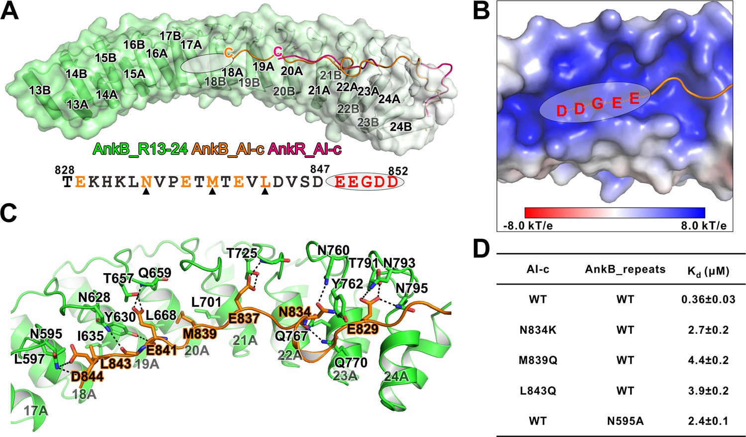
Detailed interaction between AnkB_AI-c and AnkB_MBD.
(A) Comparison of the structures of the AnkB_R13-24/AnkB_AI-c complex (colored in orange) and AnkR_C12 (colored in hot pink). The ANK repeats of AnkB are shown in cylinder and transparent surface and ANK repeats of AnkR are omitted for clarity. The folded back inhibitory sequence immediately following the ANK repeats in both structures are shown using the line model. The position of the stretch of negatively charged residues, which are not defined in the crystal structure, is indicated with a white oval. The amino acid sequence of AnkB_AI-c is also shown below the structure. Residues critical for the binding are shown in orange with those verified by mutagenesis highlighted by black triangles. (B) The charge potential surface of the inner groove formed by R16-17, calculated by the APBS module embedded in PyMOL and contoured at ±8 kT/e. (C) Detailed interactions between AnkB_AI-c and AnkB_MBD. (D) ITC derived dissociation constants showing mutations of critical residues weaken or abolish the binding between AnkB_AI-c and AnkB_MBD.
Figure 5
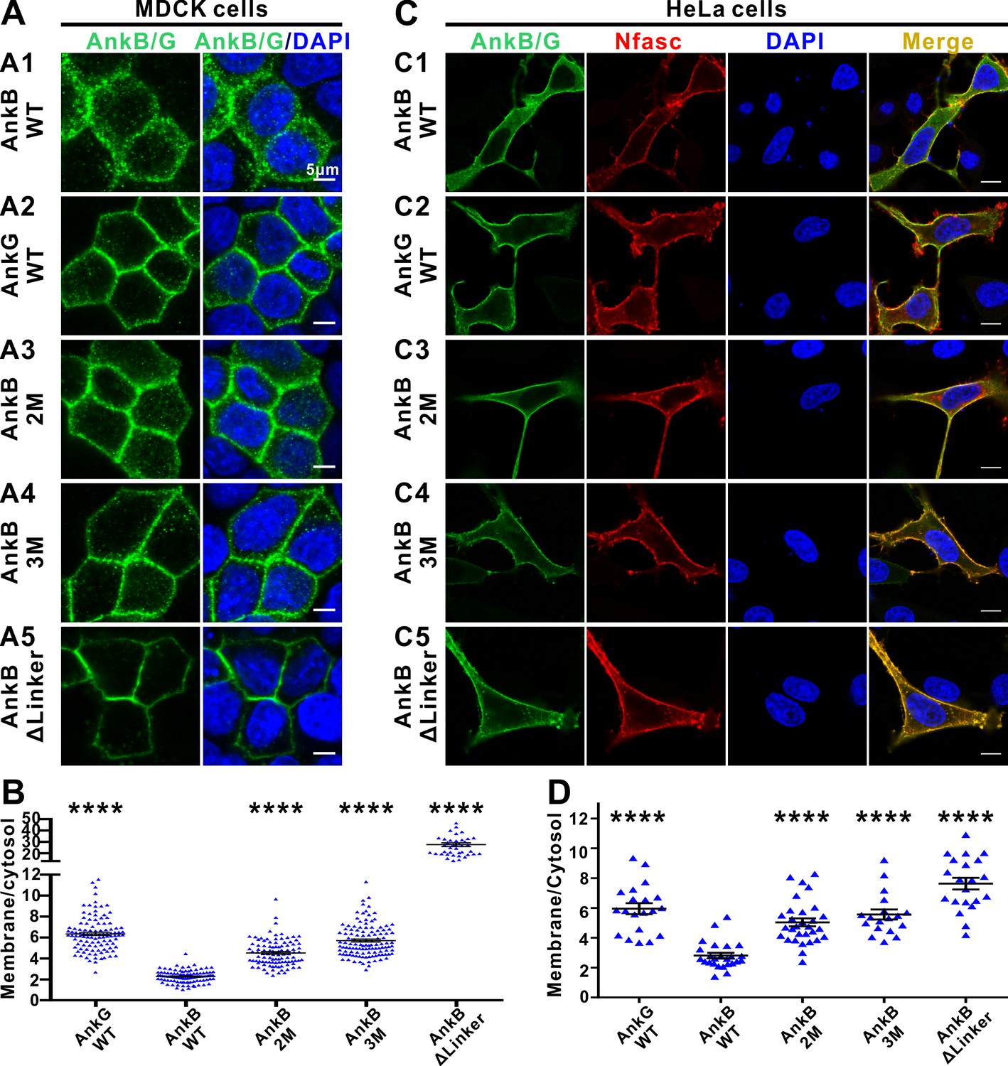
The autoinhibitory segments regulate subcellular localization of AnkB in MDCK cells and NF186-dependent membrane recruitment of AnkB in HeLa cells.
(A) Representative fluorescent images of transiently expressed GFP-tagged AnkG, AnkB or its linker mutants in polarized MDCK cells with nuclei stained with DAPI (blue): A1, WT AnkB; A2, WT AnkG; A3, AnkB_2M; A4, AnkB_3M; A5, AnkB ΔLinker. (B) Quantification of the immunofluorescence intensity ratio of plasma membrane vs cytosolic GFP signals. Data are presented as means ± SEM from>100 cells (except for AnkB ΔLinker with 41 cells due to its very clear membrane localizations) and analyzed using one way ANOVA followed by Dunnett’s multiple comparisons test to WT AnkB, ****p<0.0001. (C) Representative fluorescent images of HeLa cells transiently co-expressing HA-tagged NF186 (red) and GFP-tagged AnkG, AnkB or its linker mutants (green), with nuclei stained with DAPI (blue): C1, WT AnkB; C2, WT AnkG; C3, AnkB_2M; C4, AnkB_3M; C5, AnkB ΔLinker. (D) Quantification of the immunofluorescence intensity ratio of plasma membrane vs cytosolic GFP signals (representing AnkB/G level). Data are presented as means ± SEM from~20 cells and analyzed using one way ANOVA followed by Dunnett’s multiple comparisons test to WT AnkB, ****p<0.0001. The protein expression levels of all constructs in both cell lines are comparable as indicated by the quantified total fluorescence intensities of each groups in this experiment.
Figure 6
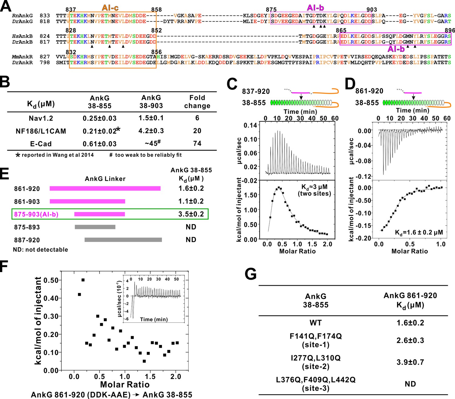
Autoinhibition of AnkG MBD by the linker region.
(A) Amino acid sequence alignment of the linker regions of AnkG, AnkB, and AnkR. The boundaries of AI-c and AI-b of AnkB and G are indicated with orange and magenta boxes. Critical residues that have been verified by mutagenesis are highlighted with black triangles. (B) ITC-derived binding affinities showing that including longer linker region to the AnkG_MBD weakened the binding towards its binding targets Nav1.2, NF186/L1CAM, and E-cadherin. (C and D) ITC profiles showing direct binding of the linker of AnkG to AnkG_MBD: C, AnkG 837–920, a linker containing both AI-b and AI-c binding to AnkG_MBD; D, AnkG 861–920, a linker containing only the AI-b, binding to AnkG_MBD. (E) ITC-based mapping of the AnkG_AI-b region. The minimal region of AI-b is indicated with a green box. (F) ITC result showing that mutating the charged residues ‘DDK’ to Ala or charge reversed residue disrupted the binding between AnkG 861–920 to AnkG 38–855. (G) ITC-derived dissociation constants of AnkG 861–920 to AnkG WT and its ‘sites-1,2,3’ mutants showing that AnkG 861–920 predominantly binds to the ‘site-3’ of AnkG_MBD.
Figure 7
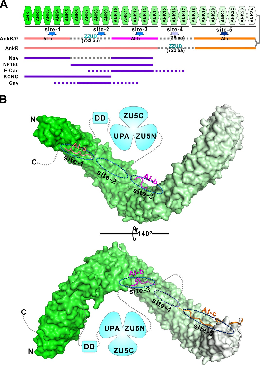
Combinatorial autoinhibitions of ankyrins and their potential regulations.
(A) Schematic diagram showing the combinatorial autoinhibition mechanisms of the three Ankyrin family members. ‘Sites-1,2,3’ are drawn according to our earlier study (Wang et al., 2014). R15-17 is assigned as ‘site-4’ based on the biochemical and structural analysis in this work and the concept that three to five ANK repeats can form a stable structural unit for target recognition, although no targets have been characterized to date. R18-24 is assigned as ‘site-5’ since it is autoinhibited by AI-c. The MBD binding sequences of the autoinhibitory segments or reported targets are shown in solid lines at corresponding positions of the bind sites. (B) Structural model of the autoinhibited full-length AnkB constructed with the three structures solved in the current study. The MBD is shown in surface representation. The three autoinhibitory segments are shown with the worm model. The unstructured loops are shown in grey dashed lines.
Tables
Table 1
Statistics of X-ray Crystallographic Data Collection and Model refinement
https://doi.org/10.7554/eLife.29150.004| Data collection | |||
|---|---|---|---|
| Data sets | RB-Chimera/AnkB_R1-20 | AI-b/AnkB_R8-M14 | AI-c/AnkB_R13-24 |
| Space group | R32 | P6522 | P212121 |
| Wavelength (Å) | 0.979 | 0.979 | 0.979 |
| Unit Cell parameters (Å) | a = b = 179.79, c = 227.10 α=β=90°, γ = 120° | a = b = 186.09, c = 75.35 α=β=90°, γ = 120° | a = 29.30, b = 127.80, c = 257.55 α=β=γ=90° |
| Resolution range (Å) | 50–3.3 (3.36–3.30) | 50–2.35 (2.39–2.35) | 50–1.95 (1.98–1.95) |
| No. of unique reflections | 20949 (1025) | 31971 (1562) | 68019 (3163) |
| Redundancy | 5.3 (5.5) | 4.1 (3.8) | 3.1 (3.2) |
| I/σ | 25.5 (3.3) | 17.0 (2.0) | 22.8 (2.4) |
| Completeness (%) | 97.6 (98.9) | 97.5 (97.9) | 94.4 (92.2) |
| Rmerge* (%) | 10.3 (72.1) | 11.4 (89.3) | 8.2 (70.3) |
| Structure refinement | |||
| Resolution (Å) | 50–3.3 (3.42–3.30) | 50–2.35 (2.42–2.35) | 50–1.95 (2.02–1.95) |
| Rcryst†/Rfree‡ (%) | 18.27/22.96 (25.40/31.06) | 19.21/23.25 (24.28/28.57) | 18.38/21.98 (24.40/29.34) |
| Rmsd bonds (Å)/angles (°) | 0.007/1.011 | 0.008/0.955 | 0.009/0.996 |
| Average B factor § | 102.8 | 46.3 | 30.9 |
| No. of atoms | |||
| Protein atoms | 5019 | 3421 | 6128 |
| Water | 0 | 64 | 274 |
| Other molecules | 50 | 102 | 5 |
| No. of reflections | |||
| Working set | 18953 | 30384 | 64519 |
| Test set | 1980 | 1540 | 3357 |
| Ramachandran plot regions § | |||
| Favored (%) | 95.2 | 98.0 | 98.7 |
| Allowed (%) | 4.8 | 2.0 | 1.3 |
| Outliers (%) | 0 | 0 | 0 |
-
Numbers in parentheses represent the value for the highest resolution shell.
* Rmerge = Σ |Ii - < I > | / ΣIi, where Ii is the intensity of measured reflection and <I > is the mean intensity of all symmetry-related reflections.
-
b† Rcryst=Σ||Fcalc| – |Fobs||/ΣFobs, where Fobs and Fcalc are observed and calculated structure factors.
c‡ Rfree= ΣT||Fcalc| – |Fobs||/ΣFobs, where T is a test data set of about 5% or 10% of the total unique reflections randomly chosen and set aside prior to refinement.
-
d§ B factors and Ramachandran plot statistics are calculated using MOLPROBITY (Chen et al., 2010).
Table 2
Constructs of ankyrins used in this study
https://doi.org/10.7554/eLife.29150.006| AnkB | AnkG | |
|---|---|---|
| AI-a | 1623–1635 | 1596–1608 |
| AI-b | 865–896 | 875–903 |
| AI-c | 828–852 | 837–858 |
| Linker (contains AI-c + AI b) | 828–965 | |
| AI-c + AI-b | 828–896 | 837–920 |
| Linker ΔAI-c | 861–920 | |
| MBD + partial AI-c | 28–847 | 38–855 |
| MBD + full AI-c | 28–873 | |
| MBD + AI c+AI-b | 28–965 | 38–903 |
| ΔZZUD | ||
| MBD | 28–827 | 38–837 |
Additional files
-
Transparent reporting form
- https://doi.org/10.7554/eLife.29150.012
Download links
A two-part list of links to download the article, or parts of the article, in various formats.
Downloads (link to download the article as PDF)
Open citations (links to open the citations from this article in various online reference manager services)
Cite this article (links to download the citations from this article in formats compatible with various reference manager tools)
Autoinhibition of ankyrin-B/G membrane target bindings by intrinsically disordered segments from the tail regions
eLife 6:e29150.
https://doi.org/10.7554/eLife.29150


