The follicle epithelium in the Drosophila ovary is maintained by a small number of stem cells
- University of California, San Francisco, United States
Figures
Figure 1 with 2 supplements
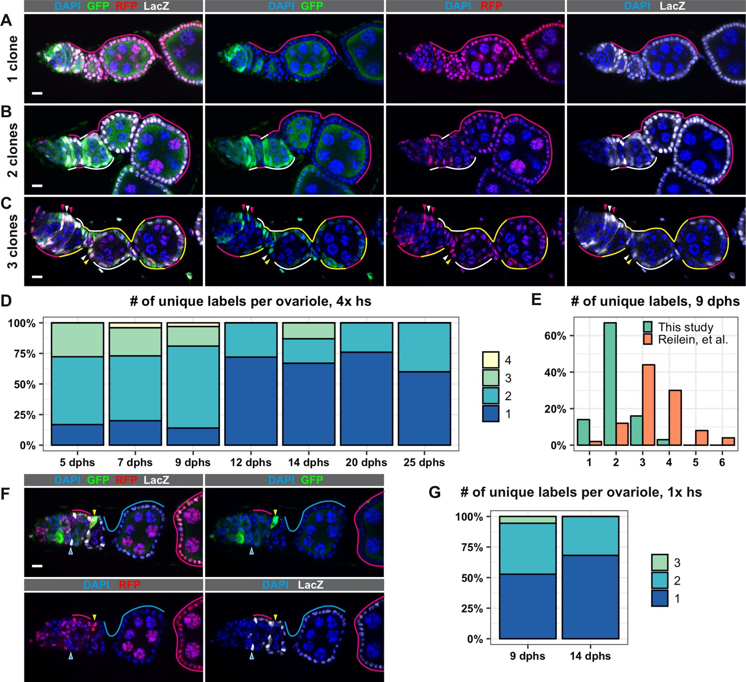
The LGR system labels clones with distinct marker combinations.
(A–G) Analysis of LGR clones within the follicle epithelium, ranging from the Region 2a/2b border of the germarium to the first 2–3 follicles downstream from the germarium following four 1 hr heat shocks (A–F) or one 1 hr heat shock (G). (A–C) Examples of LRG clones at 7 days after the last heat shock (dphs) with 1 (A), 2 (B), or 3 (C) uniquely marked clones. Marker combinations present in these ovarioles are: LacZ+ GFP+ RFP+ (white lines and arrowheads), LacZ– GFP+ RFP+ (yellow lines and arrowheads), LacZ+ GFP– RFP+ (magenta lines and arrowheads). (D) Quantification of the number of uniquely labeled clones per ovariole after four 1 hr heat shocks at the indicated dphs, Total n = 242; five dphs n = 18, seven dphs n = 91, nine dphs n = 43, 12 dphs n = 36, 14 dphs n = 15, 20 dphs n = 29, 25 dphs n = 10. (E) Comparison of the number of the uniquely labeled clones per ovariole at nine dphs in our study (n = 43) and Reilein et al. (n = 50, taken from the Supplemental Note, Table a) plotted as a percent of total. (F) Example of an ovariole with two large clones that span multiple follicles (cyan triangle and cyan and magenta lines) and one small clone in the germarium (yellow triangles). (G) Quantification of the number of uniquely labeled clones per ovariole after one 1 hr heat shock at 9 and 14 dphs, Total n = 58; nine dphs n = 22, 14 dphs n = 36. Scale bars represent 10 μm.
-
Figure 1—source data 1
Frequency of clones over a time course, LRG system, 4x heat shocks.
- https://cdn.elifesciences.org/articles/49050/elife-49050-fig1-data1-v2.csv
-
Figure 1—source data 2
Comparison of this study with Reilein et al. (2017).
- https://cdn.elifesciences.org/articles/49050/elife-49050-fig1-data2-v2.csv
-
Figure 1—source data 3
Frequency of clones over a time course, LGR system, 1x heat shock.
- https://cdn.elifesciences.org/articles/49050/elife-49050-fig1-data3-v2.csv
Figure 1—figure supplement 1

The Drosophila germarium and the LGR system.
(A) Diagram of the Drosophila germarium and recently budded follicles. Cell types are colored as indicated (TF is terminal filament, GSC is germline stem cell, IGS is inner germarial sheath, FSC is follicle stem cell, pFC is prefollicle cell, and MB FC is main body follicle cell) and designations for the regions of the germarium and stages of follicle development are indicated below. (B) Diagram showing the arrangement of marker genes and FRT sites in the LGR system and a table showing the six predicted marker combinations that can be produced by FRT recombination.
Figure 1—figure supplement 2
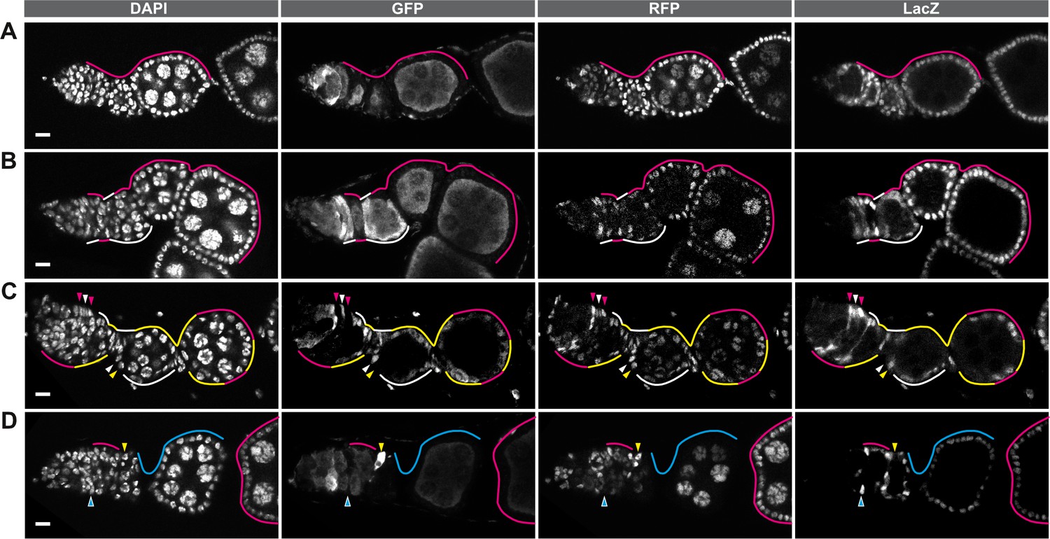
Individual channels of the four-color images.
(A–D) Each of the four channels of the images in Figure 1 shown separately in monochrome. Panels A-C in Figure 1 correspond to panels A-C and panel F in Figure 1 corresponds to panel D. White lines and arrowheads indicate LacZ+ GFP+ RFP+, yellow lines and arrowheads indicate LacZ– GFP+ RFP+, magenta lines and arrowheads indicate LacZ+ GFP– RFP+, and cyan lines and arrowheads indicate LacZ+ GFP– RFP–. Scale bar represents 10 μm.
Figure 2

The LGR system is unreliable.
(A) The frequency of ovarioles with either the negatively-marked FRT 19A system or the LGR system that have FSC clones (with or without transient clones), transient clones (without an FSC clone) or no clones at 7 days post eclosion in the absence of heat shock. Flies of both genotypes were maintained in vials from the same batch of food and kept in the same box at 25°C to minimize differences between cohorts, n = 153 for GFP negative system and n = 115 for LGR system. (B) Example of an ovariole with a large LacZ+ GFP– RFP– FSC clone from LGR flies that had not been heat shocked (cyan lines). (C–E) Examples of ovarioles with clones that have marker combinations that are not expected given the arrangement of the marker genes in the LGR system, including clones that are LacZ– GFP– RFP– (white triangles and lines in C-D) and LacZ– GFP– RFP+ (yellow triangles in E). Scale bar represents 10 μm.
-
Figure 2—source data 1
No heat shock control, LGR system vs GFPneg system.
- https://cdn.elifesciences.org/articles/49050/elife-49050-fig2-data1-v2.csv
Figure 3
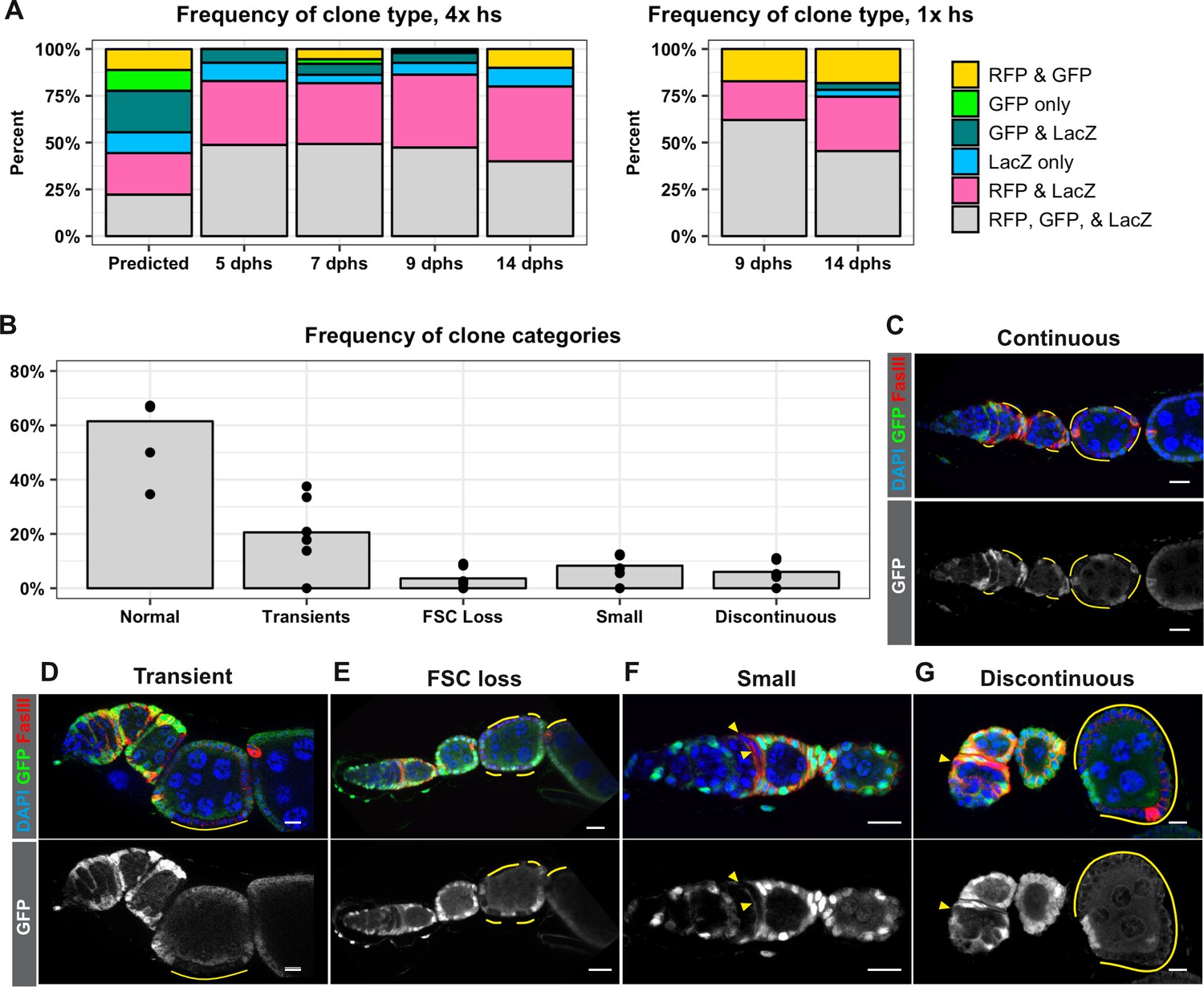
FRT recombination produces contiguous clones and does not occur in every cell.
(A) A comparison of the frequency of each combination of clonal markers that would be predicted if recombination at both FRT sites occurred in all FSCs with the actual frequencies of clone types observed following either four 1 hr heat shocks or one 1 hr heat shock at the indicated dphs. For 4x hs, n = 242 and for 1x hs, n = 84. (B–G) A graph showing the frequencies of each type of clone observed with the negatively-marked FRT 19A system (B, n = 136) and examples of each clone type (C–G). GFP– cells indicated by yellow lines and triangles. Scale bar represents 10 μm.
-
Figure 3—source data 1
Frequency of each type of clone over a time course, LGR system, 4x heat shocks.
- https://cdn.elifesciences.org/articles/49050/elife-49050-fig3-data1-v2.csv
-
Figure 3—source data 2
Frequency of each type of clone over a time course, LGR system, 1x heat shock.
- https://cdn.elifesciences.org/articles/49050/elife-49050-fig3-data2-v2.csv
-
Figure 3—source data 3
Frequency of each type of clone pattern, GFPneg system.
- https://cdn.elifesciences.org/articles/49050/elife-49050-fig3-data3-v2.csv
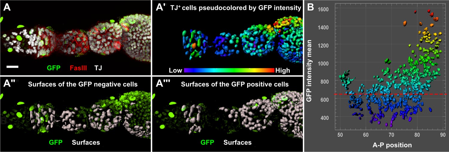
Figure 4 with 1 supplement
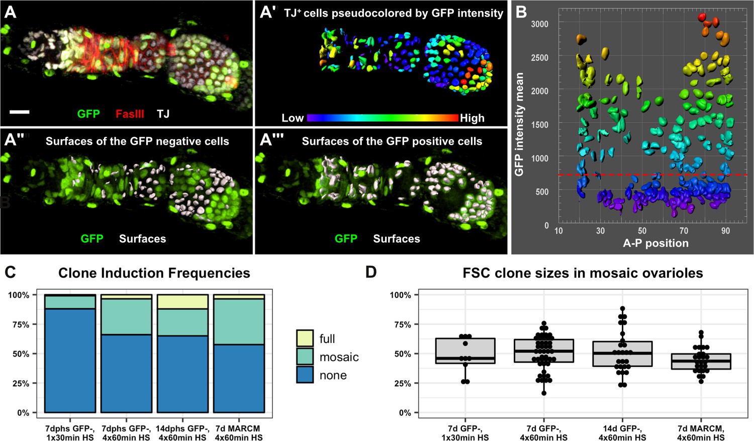
The follicle epithelium is typically maintained by two actively dividing FSCs.
(A) 3D rendering of an ovariole stained for FasIII (red), GFP (green) and traffic jam (white). The traffic jam channel was used to generate surfaces around each somatic cell from the Region 2a/2b border to the posterior end of the clone (A’, surfaces are pseudocolored according to mean intensity in the GFP channel). GFP negative surfaces are shown with the GFP channel (green) in A" and GFP positive surfaces are shown with the GFP channel in A’’’. (B) Surfaces were arrayed on a scatter plot according to the anterior/posterior position of each surface on the x-axis and the mean GFP intensity of each surface along the y-axis. The scatter plot was used to identify the threshold of GFP signal that differentiates between GFP negative and GFP positive cells (red dashed line). The 3D rendering (A’’ and A’’’) was used to confirm the accuracy of the threshold and make adjustments to the threshold if necessary. (C) GFP negative FRT19A clones were induced with either one 30 min heat shock or four 1 hr heat shocks and analyzed at either 7 or 14 dphs. MARCM 19A clones were induced with four 1 hr heat shocks and analyzed at seven dphs. The percentage of ovarioles in which there are no FSC clones (‘none’), an FSC clone that does not fully encompass each follicle (‘mosaic’), and an FSC clone that fully encompases each follicle (‘full’) with the indicated experimental conditions. n = 243 for 30 min heat shock; n = 189 for 4 × 1 hr heat shock, 7dphs; and n = 181 for 4 × 1 hr heat shock, 14dphs; and n = 85 for MARCM19A. Clonal labeling was sparse, with no FSC clones in more than half of the ovarioles in all cases. (D) Quantification of clone size in mosaic ovarioles with continuous FSC clones extending from the Region 2a/2b border into the budded follicles indicates that, for all four experimental conditions, mean clone sizes are approximately 50% and are not significantly different from one another. For the GFP negative clones, n = 10 for the 30 min heat shock; n = 47 for 4 × 1 hr heat shock, 7dphs and n = 28 for 4 × 1 hr heat shock 14dphs. For MARCM clones, n = 25. p>0.5 for all pairwise comparisons. Scale bar represents 10 μm.
-
Figure 4—source data 1
Frequency of clones in each experimental condition, GFPneg system and MARCM system.
- https://cdn.elifesciences.org/articles/49050/elife-49050-fig4-data1-v2.csv
-
Figure 4—source data 2
Clone sizes in each experimental condition, GFPneg system and MARCM system.
- https://cdn.elifesciences.org/articles/49050/elife-49050-fig4-data2-v2.csv
Figure 4—figure supplement 1
Quantification of MARCM clone sizes.
(A) 3D rendering of an ovariole with a GFP+ MARCM clone stained for FasIII (red), GFP (green) and traffic jam (white). All surfaces, colored according to the mean intensity in the GFP channel, are shown in A’, GFP– surfaces shown with the GFP channel (green) in A’ and GFP+ surfaces shown with the GFP channel in A’’’. Images were analyzed and surfaces arrayed on a scatter plot (B) as described for negatively marked clones (Figure 4).
Figure 5
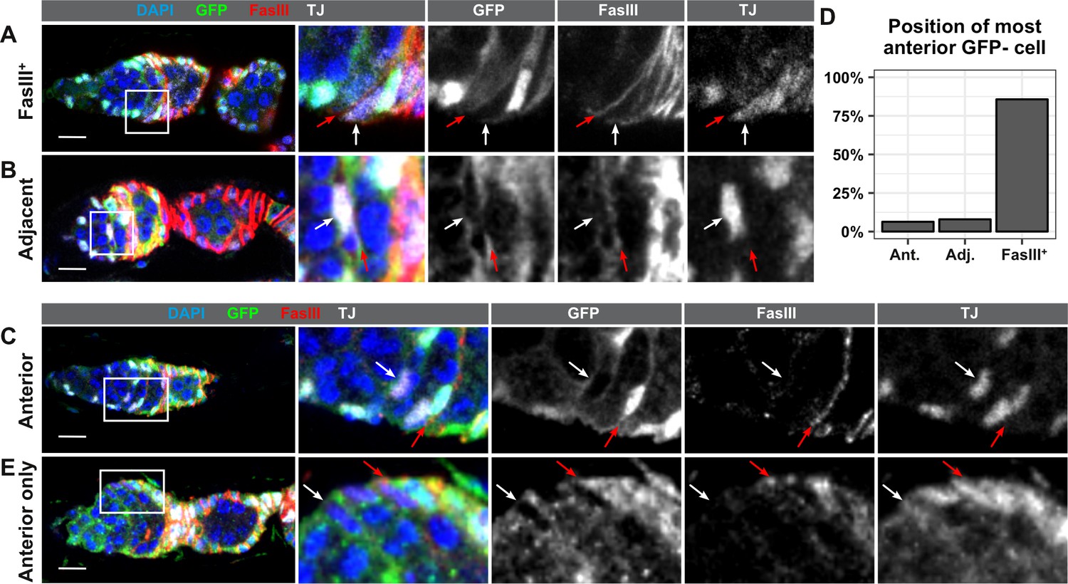
FSCs typically reside within the FasIII domain.
(A–C) Ovarioles with GFP-negative FRT19A FSC clones stained for FasIII (red), GFP (green), and DAPI (blue) in which the anterior-most GFP-negative cell is FasIII+ and located at the boundary of FasIII expression (A, ‘FasIII+”), FasIII– and located adjacent to the boundary of FasIII expression (B, ‘Adjacent’), or FasIII– and anterior to the boundary of FasIII expression (C, ‘Anterior’). (D) Quantification of the percentage of FSC clones in which the anterior-most GFP-negative cell is in each position, n = 61. (E) An ovariole with a GFP– cell in the ‘anterior’ position in a germarium without an FSC clone. White arrows indicate the anterior-most GFP– cell and red arrows indicate the boundary of FasIII expression. Scale bar represents 10 μm.
Tables
Key resources table
| Reagent type (species) or resource | Designation | Source or reference | Identifiers | Additional information |
|---|---|---|---|---|
| Genetic reagent (D. melanogaster) | hsFlp; Ubi-GFP, FRT40a, FRT42D, Ubi-RFP | Reilein et al., 2017 | ||
| Genetic reagent (D. melanogaster) | Tub-LacZ, FRT40a/CyO | Reilein et al., 2017 | ||
| Genetic reagent (D. melanogaster) | y1,w*, FRT 19A | Yamamoto et al., 2014 | ||
| Genetic reagent (D. melanogaster) | w122, hsFlp, Ubi-GFP, FRT 19A | Yamamoto et al., 2014 | ||
| Genetic reagent (D. melanogaster) | hsFlp, tub-Gal80ts, FRT19A; Act5C-Gal4, UAS-CD8::GFP/CyO | Built from BDSC stocks 5132 and 25374 |
Additional files
-
Source data 1
RData file.
- https://cdn.elifesciences.org/articles/49050/elife-49050-data1-v2.zip
-
Source code 1
R script file.
- https://cdn.elifesciences.org/articles/49050/elife-49050-code1-v2.zip
-
Transparent reporting form
- https://cdn.elifesciences.org/articles/49050/elife-49050-transrepform-v2.docx
Download links
A two-part list of links to download the article, or parts of the article, in various formats.
Downloads (link to download the article as PDF)
Open citations (links to open the citations from this article in various online reference manager services)
Cite this article (links to download the citations from this article in formats compatible with various reference manager tools)
The follicle epithelium in the Drosophila ovary is maintained by a small number of stem cells
eLife 8:e49050.
https://doi.org/10.7554/eLife.49050


