Data-driven reduction of dendritic morphologies with preserved dendro-somatic responses
- Department of Physiology, University of Bern, Switzerland
Figures
Figure 1 with 1 supplement

Flexible and accurate reduction methodology.
(A) For any set of locations on a given morphology (left, here an L2/3 pyramidal cell [Branco and Häusser, 2010]), a reduced compartmental model can be derived (middle), with an associated schematic representation (right). (B) Steps of our approach: (1) choice of locations at which the reduced model should reproduce the full model’s voltage, (2) coupling, leak and channel conductances are fitted to resistance matrices derived from the full model at different holding potentials, and (3) capacitances are fitted to mimic the largest eigenmode of the full model. (C) The resistance matrix of the passive full model (top) restricted to the five locations in A is approximated accurately by the inverse of the conductance matrix of the passive reduced model (bottom). Labels correspond to locations in A. (D) Example components of the quasi-active resistance matrix of the full model, equipped with a Na+-channel, as a function of the holding potential . Red lines show the four holding potentials at which our methodology evaluates the resistance matrix. Singularities correspond to holding potentials where the linearization is invalid and should be avoided in the fit. Labels correspond to locations in A. (E) Temporal shape of exemplar input impedance kernels of the full model (gray) and their reduced counterparts (blue, dashed). (F) Same as in E, but for transfer impedance kernels.
Figure 1—figure supplement 1
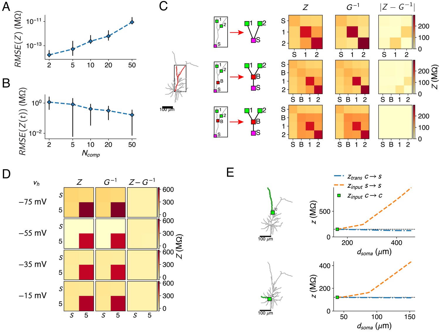
Resistance matrix fit details.
(A) Error of the reduced model’s resistance matrix compared to the full model’s resistance matrix, for reductions of the passive L2/3 pyramid with 2, 5, 10, 20, and 50 compartments. Five random sets of fit locations were chosen for each compartment number; mean (marker) and standard deviation (error bars) are shown. (B) Same as A, but for the impedance kernels. (C) The bifurcations between compartment sites need to be added, as shown in the red forked dendrite (left). Soma and two compartment sites 1, 2 (top) were augmented with a site on the main trunk (but not at a bifurcation, middle) or a site at the bifurcation (bottom). Reductions were derived for all three configurations, but only the last configuration can accurately approximate all resistances (right). (D) Resistance matrices for the soma S and location five in Figure 1A, with Na+-channels at the soma. The resistance matrix (first column) depends on . The inverse of the matrix (second column) is fitted by adjusting the maximal Na+ conductance parameter so that at the four holding potentials. matches closely, as the difference between both matrices is close to zero (third column). (E) Behavior of the input and transfer resistances between a compartment site (green square) and a synapse site located more distally on the same subtree (only a single branch is shown for clarity, marked in green). Transfer resistance between and remains close to the input resistance at , while input resistance at increases markedly with distance. This principle holds in the apical (top) as well as basal (bottom) dendrites.
Figure 2
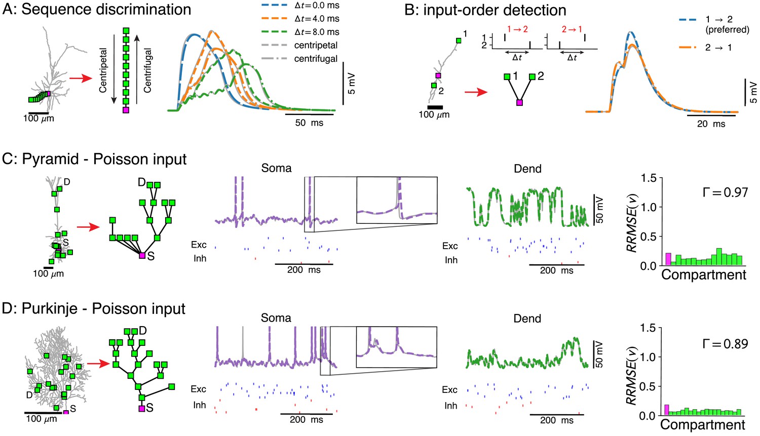
Voltage-match between full and reduced models for spatio-temporal dendritic computations.
(A) Reduction of full model (right) to a single branch (middle) reproduces sequence discrimination (right), full model in gray, and reduced model colored for different time-steps between inputs, centripetal (dashed), and centrifugal (dash-dotted). (B) Full model (left) and three-compartment reduction (middle, bottom) discriminate temporal order of inputs, where the response to inputs (middle, top) ordered is stronger than . Voltage responses (right) in full model (gray) and reduced model (colored). (C, D) Reductions of resp. L5 pyramidal and Purkinje cells with active ion channels at the soma, and excitatory (AMPA+NMDA) and inhibitory (GABA) synapses at dendritic compartment sites. From left to right: full model with compartment sites (soma S and a selected dendrite site D are labeled), reduced model, somatic voltage with zoom on a single AP (full model in gray and reduced model in purple, input spikes at the bottom), dendritic voltage at D (full model in gray and reduced model in green, input spikes at the bottom), and the relative root mean square voltage errors at each compartment (root mean squared error normalized by the standard deviation ). Spike coincidence factor is also shown.
Figure 3 with 1 supplement
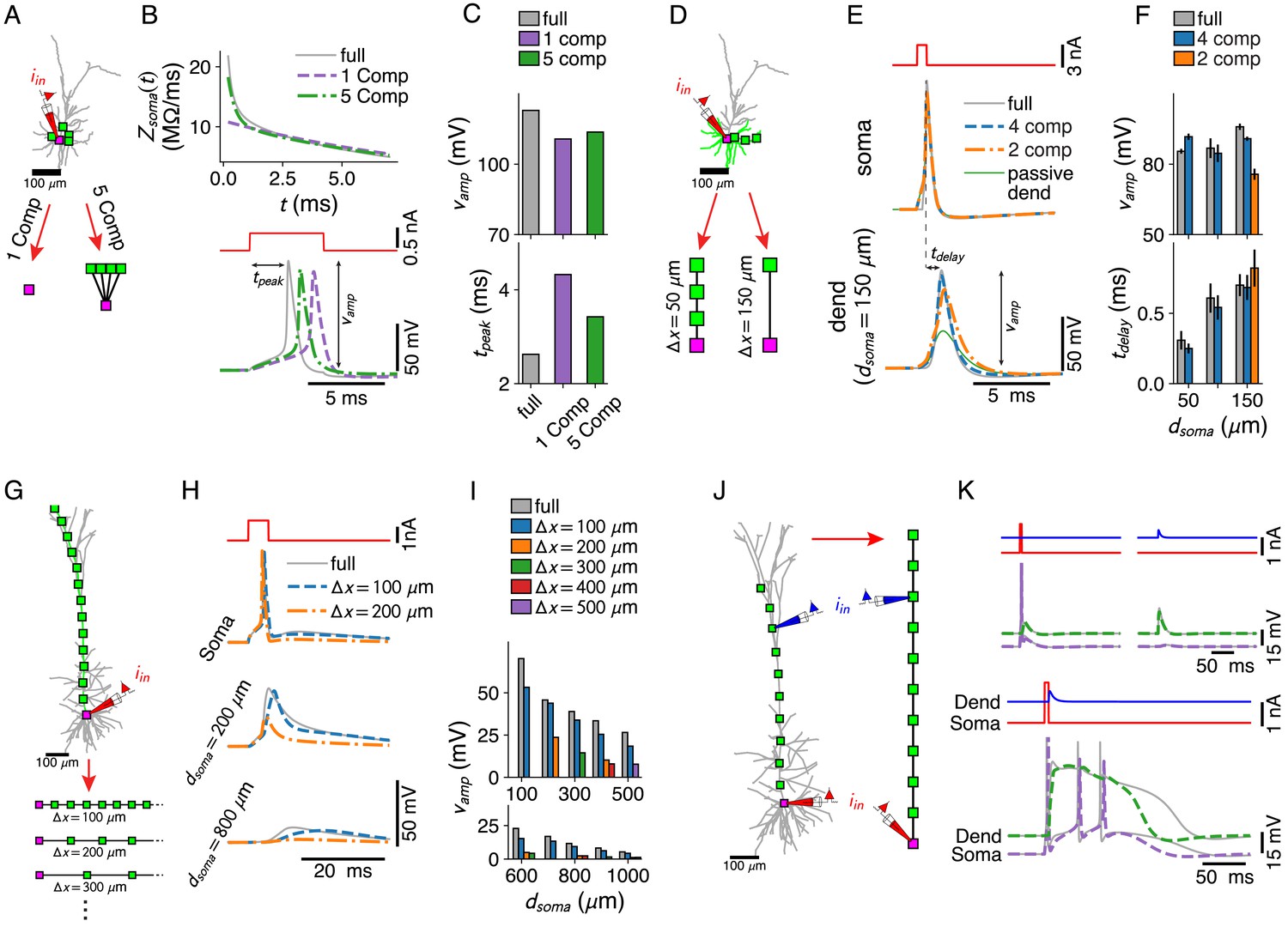
Dendritic computations with active channels are captured by our reduced models.
(A–C) Effect of compartment distribution on AP dynamics in reduced models. (A) One- and five-compartment reductions of the L2/3 pyramid, equipped with somatic and dendritic ion channels. (B) Differences in short time-scale behavior in somatic input impedance kernels (top) between full model (gray) and one- (purple) and five-compartment (green) reductions result in different AP delays (bottom). (C) AP amplitude (top) and AP delay (bottom) for the three models (colors as in B). (D–F) Effect of compartment distribution on AP back-propagation in basal dendrites. (D) Four- and two-compartment reductions of a basal branch. (E) APs at soma (top) and most distal compartment site (bottom) for four models (full in gray, four compartments in blue, two compartments in orange, and full but with a passive dendrite in green). (F) Amplitude (top) and delay (bottom) for bAPs at different distances from soma (if compartment is present in model), averaged over all basal branches longer than 150 μm (error bars indicate standard deviation). (G–I) AP back-propagation in the apical dendrite of the L5 pyramid. (G) Reductions of the apical dendrite with increasing inter-compartment spacing. (H) Voltage waveform at soma (top, full in gray, μm in blue, μm in orange) and two dendritic sites (middle, bottom). (I) Waveform amplitude as a function of distance to soma for various inter-compartment spacings. (J, K) Ca2+-spike-mediated coincidence detection. (J) Reduction of the L5-pyramid’s apical dendrite to 11 compartments. (K) Response to a somatic current pulse (top, left), a dendritic synaptic current waveform (top, right), and the coincident arrival of both inputs (bottom).
Figure 3—figure supplement 1
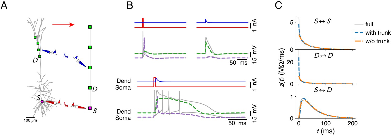
Further reduction of the configuration in Figure 3J by omitting compartments in the apical trunk of the L5 pyramid.
(A) The compartment sites on the morphology. (B) Ca2+ mediated coincidence detection between somatic and dendritic inputs does not result in an AP burst. Response to a somatic current pulse (top, left), a dendritic synaptic current waveform (top, right), and the coincident arrival of both inputs (bottom). Stimulus parameters where identical to Figure 3, except the amplitude of the dendritic input current, which was increased to 0.75 nA. (C) Somatic input impedance kernel (top), input impedance kernel at most proximal dendritic location (middle, marked with D in A) and transfer impedance kernel between soma and dendritic location. Full model (gray), reduction with trunk (blue, configuration as in Figure 3J), and reduction without trunk (orange, configuration as in A).
Figure 4

Simplification of afferent spatial connectivity motifs.
(A) Removal of a branch with a synapse (red triangle) is considered possible if the correct voltages at the compartment sites (here, dendritic – green square and somatic – purple square) can be obtained by shifting the synapse to the compartment site and rescaling its weight with a fixed factor for the all input conditions under consideration. (B) Comparison between weight-rescale factors for current-based (left) and conductance-based (right) input. Voltage trace for dendritic compartment without rescaling (gray) and with the current-based scale factor compensating for attenuation (blue). Bottom right panel shows voltage trace with conductance-based scale factor . (C) Current- and conductance-based scale factors in the green dendritic branch, for a shift of a synapse at a given distance from the soma to the dendritic compartment site (green square). (D) Spatial peak voltage without (left, blue) and with (right, orange) application of . (E) For a cluster of AMPA+NMDA synapses in isolation, scale factors for physiological constants can be obtained (see Materials and methods — Synaptic weight-rescale factors) that reproduce the correct voltage waveform. Colors as in D. (F) Maximal amplitude of NMDA-spike waveform upon activation of increasing numbers of synapses – NMDA-spike thresholds indicated with vertical lines. Colors as in D. (G–H) Removing a whole subtree and shifting multiple synapses (red triangles) to the next proximal compartment site (green square). NMDA-spike generation (gray voltage trace) at the compartment site through burst inputs to local AMPA+NMDA synapses (green inputs), with AMPA (blue) and GABA (red) background inputs spread throughout the subtree. Reductions shown without rescaling (blue, dash-dotted), with the analytical single-site rescaling rule (red, full) and the numerical multi-site rule (orange, dashed). (I) Error in NMDA-spike threshold for the three cases in H. (J) Dependence of the error in NMDA-spike threshold on the factor , with the average input resistance difference between synapse sites and the compartment and the average synaptic conductance.
Figure 5 with 1 supplement
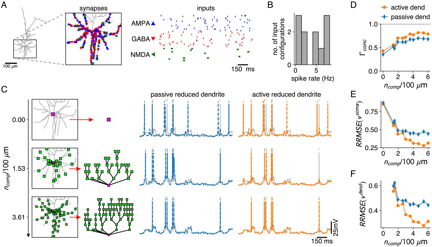
Reductions with active and passive dendritic compartments under in vivo like conditions.
(A) AMPA and GABA synapses, and AMPA+NMDA synapse clusters are spread randomly throughout the basal dendrites of the L2/3 pyramid (inset). AMPA and GABA synapses receive Poisson inputs and AMPA+NMDA synapses receive bursting input (right). (B) Output spike rates of the full model for 10 different input configurations. (C) Reductions with increasing numbers of compartment sites along the basal dendrites (left). Somatic voltage traces and spike times for the full model (gray), for a reduction with passive dendrites (middle, blue) and a reduction with active dendrites (right, orange). (D–F) Spike coincidence factors (D), relative somatic voltage errors (E) and relative dendritic voltage errors (F) for reductions with increasing numbers of compartments, and with passive (blue) and active dendrites (orange), averaged over all 10 input configurations. Relative voltage errors are computed as in Figure 2C,D.
Figure 5—figure supplement 1
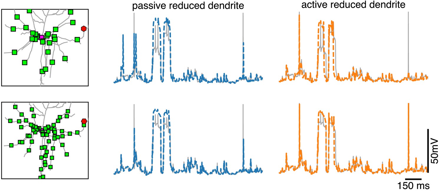
Dendritic voltage traces for reductions with passive and active dendrites.
Voltage in the full model (gray) at a dendritic site (red hexagon on the left), together with the voltage in the closest compartment of the reduced model with passive dendrite (middle, blue) and of the reduced model with active dendrites (left, orange) for the same simulations as in Figure 5.
Figure 6

Fitting reduced models directly to experimental data.
(A) Comparison between the traditional neuron model creation paradigm (morphological reconstruction and evolutionary fit, possibly followed by a reduction), and the proposed direct experiment to reduced dendrite model paradigm. (B) Resistance matrices and holding potentials are extracted from the response amplitude to hyper- and depolarizing current step inputs, here measured once under application of an h-channel antagonist and once under control conditions. (C) Time scale of largest eigenmode is extracted from average decay back to the resting membrane potential. (D) Combined root mean square voltage error of full model (gray) – fitted to current step data through an evolutionary algorithm, of the reduction of the full model (red), and of the direct fit of the reduced model to the data (brown). (E) Experimentally recorded traces (gray), traces from the full reconstruction (black), and its reduction (green and purple, dashed). (F) Experimentally recorded traces (gray) and traces from the directly fitted reduced model (green and purple, dashed).
Additional files
Download links
A two-part list of links to download the article, or parts of the article, in various formats.
Downloads (link to download the article as PDF)
Open citations (links to open the citations from this article in various online reference manager services)
Cite this article (links to download the citations from this article in formats compatible with various reference manager tools)
Data-driven reduction of dendritic morphologies with preserved dendro-somatic responses
eLife 10:e60936.
https://doi.org/10.7554/eLife.60936


