Extreme suction attachment performance from specialised insects living in mountain streams (Diptera: Blephariceridae)
- Department of Zoology, University of Cambridge, United Kingdom
- Carl Zeiss Research Microscopy Solutions, United Kingdom
Figures
Figure 1
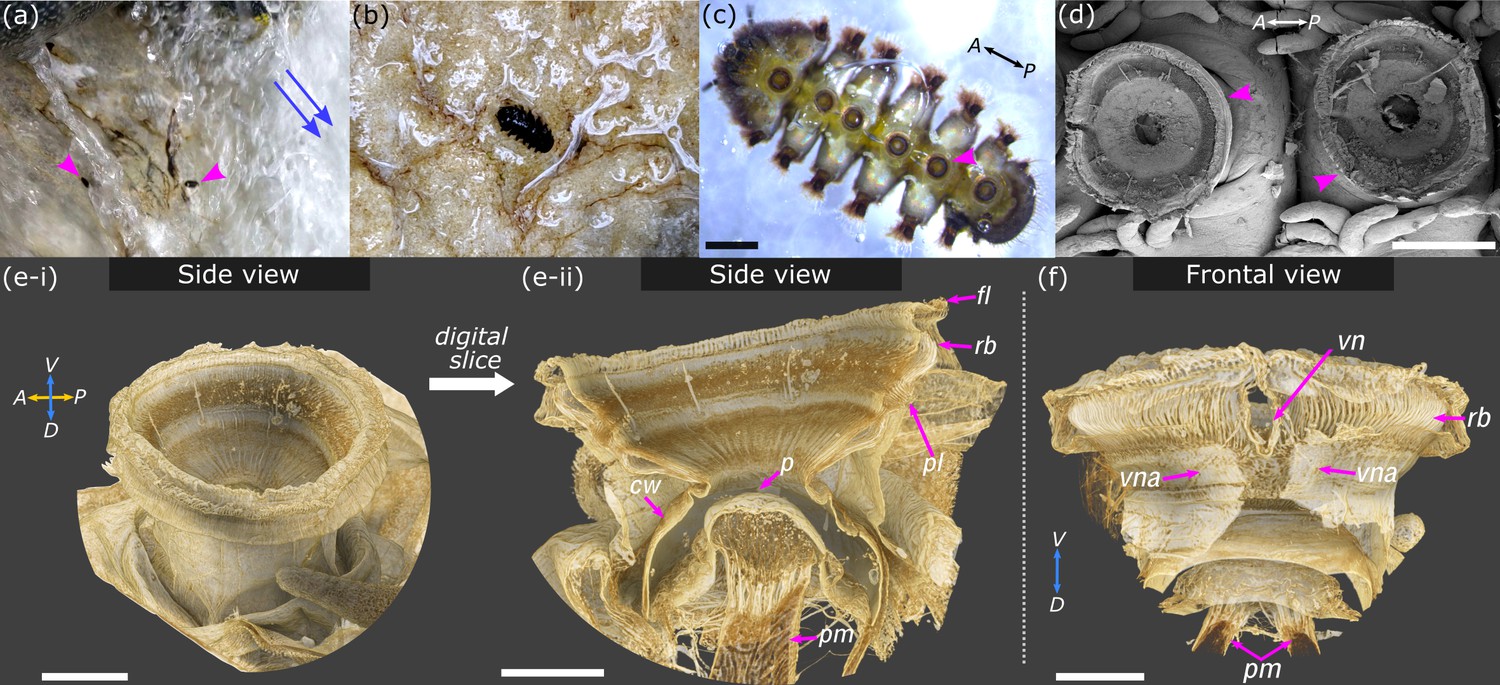
Overview of Hapalothrix lugubris and their suction attachment organs.
(a) Hapalothrix lugubris larvae live attached to rocks in torrential alpine waterways. Blue arrows indicate stream flow direction. Arrowheads highlight two larvae revealed from a brief obstruction of the waterflow. (b) H. lugubris larva (dorsal view) on natural substrate. (c) Ventral view of a larva showing its six suction organs (one organ marked by arrowhead). (d) Scanning electron micrograph showing two suction organs (arrowheads). (e-i) Computed microtomography rendering of one whole organ. A: anterior, P: posterior, D: dorsal, V: ventral. (e-ii) Side view after digital dissection showing the following structures: outer radial beams (rb), palisade layer (pl), piston cone (p), and piston muscles (pm). The cuff wall (cw) encircles the suction cavity, and the outer fringe layer (fl) encircles the disc. (f) Frontal view showing the V-notch (vn) and its pair of apodemes (vna) extending dorsally into the body. Outer cuticle has been digitally dissected to reveal the radial beams. Note the pair of piston muscles extending dorsally. V: ventral, D: dorsal. Scale bars: (c) and (d) 500 µm; (e-i), (e-ii), and (f) 100 µm.
Figure 2
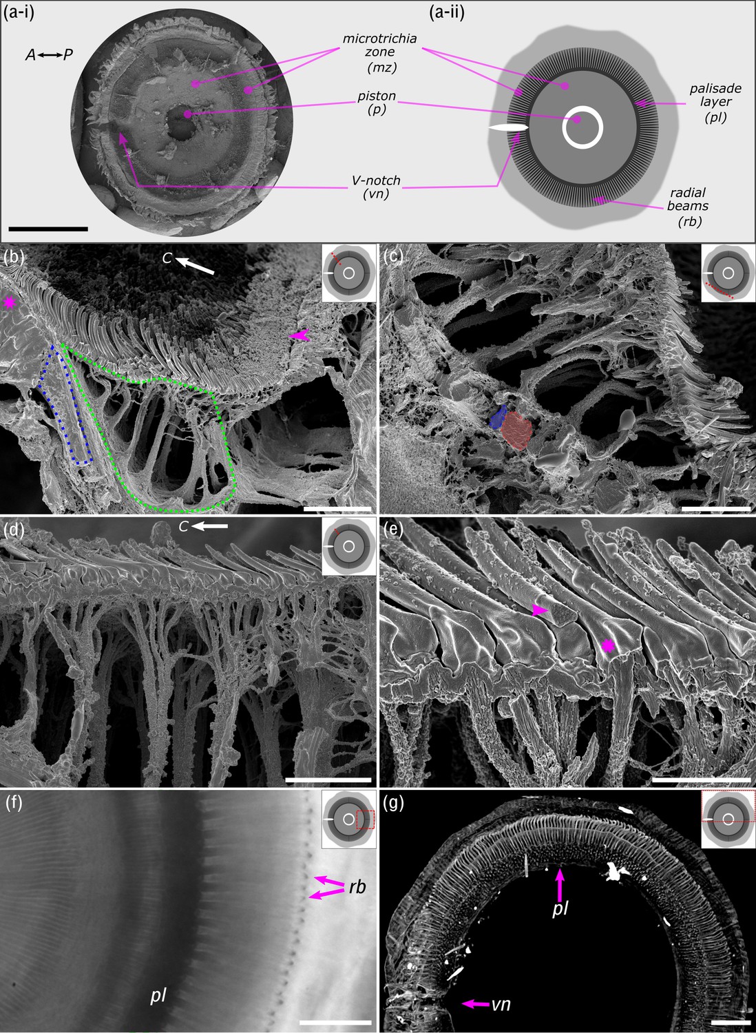
Ultrastructure of the suction disc.
(a-i) Scanning electron micrograph showing ventral view of the suction disc. The piston is withdrawn into the suction chamber (see Figure 1d). (a-ii) Schematic of the suction disc used for subsequent panels. Note the radial beams (rb) are beneath the outer cuticle layer and not visible in (a-i) but shown in (b) and (c). (b) Freeze-fractured suction disc (radial fracture plane; see dotted red line on suction disc schematic). The sealing rim and its short rim microtrichia are marked by an arrowhead. Internal radial beams (encircled in blue) originate from the palisade layer (magenta*). The fan-fibre space is encircled in green. C: disc centre. (c) Fan-fibres extend to the radial beams, which alternate between thin (blue) and wide beams (red). (d) Each microtrichium connects to an internal fibre; these fibres represent the ends of thicker branched fibres originating from the radial beams. Note: spine-like microtrichia point towards the disc centre (C). (e) Microtrichia are largely solid cuticular structures (arrowhead), each connected to a fan-fibre (*). (f) In vivo light microscopy shows the radial beams and the palisade layer (pl). (g) Computed microtomography (micro-CT) also shows that radial beams originate from the dorsoventral palisade layer. Centre-to-centre spacing of the beams is around 4 µm or 1.3°. vn: V-notch. Scale bars: (a) 200 µm; (b) 10 µm; (c) 6 µm; (d) 5 µm; (e) 2 µm; (f) 20 µm; (g) 40 µm.
Figure 3

Attachment performance of Hapalothrix lugubris larvae on surfaces of varying roughness.
Hapalothrix lugubris larvae performance in (a) peak shear force per body weight and (b) peak normal adhesion force per body weight. The rotation of the centrifuge is indicated by the red circular arrow. Centre lines, boxes, whiskers, and filled dots represent the median, the inter-quartile range (IQR), 1.5 times IQR, and outliers, respectively.
-
Figure 3—source data 1
Data for Figure 3.
- https://cdn.elifesciences.org/articles/63250/elife-63250-fig3-data1-v1.csv
Figure 4
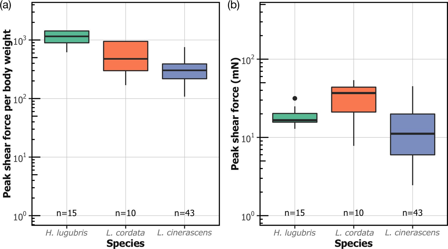
Attachment performance of three species of blepharicerid larvae (Hapalothrix lugubris, Liponeura cordata, Liponeura cinerascens) on smooth horizontal surface.
(a) Peak shear force per body weight. (b) Peak shear force.
-
Figure 4—source data 1
Data for Figure 4.
- https://cdn.elifesciences.org/articles/63250/elife-63250-fig4-data1-v1.csv
Figure 5

Comparison of shear attachment performance of Hapalothrix lugubris larvae versus stick insects (Carausius morosus) on smooth and rough surfaces.
Hapalothrix lugubris larvae attach using suction organs, whereas stick insects rely on smooth adhesive pads and claws. Sample sizes are shown with H. lugubris on the left and stick insects on the right.
-
Figure 5—source data 1
Data for Figure 5.
- https://cdn.elifesciences.org/articles/63250/elife-63250-fig5-data1-v1.csv
Figure 6
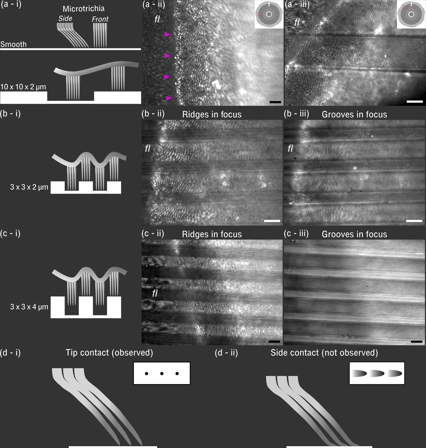
In vivo visualisation of Hapalothrix lugubris suction disc contact on different substrates.
(a-i) Schematic of the microtrichia on smooth and 10 × 10 × 2 µm microstructured surface (ridges and grooves, 10 µm in width, and grooves, 2 µm deep) (shown to scale). (a-ii) On smooth glass, microtrichia made tip contact (seen as black dots under interference reflection microscopy [IRM]). Outer fringe layer (fl) is outside the seal (arrowheads). (a-iii) On 10 × 10 × 2 µm substrates, contact from microtrichia and fl was similar to the contact on the smooth surface. (b-i and b-ii) On 3 × 3 × 2 µm substrates, the microtrichia made tip contact on the ridges, as well as in the grooves, as seen in (b-iii). However, fewer microtrichia made contact within the narrow grooves compared to the 10 × 10 × 2 µm surface. Note that (b-ii) and (b-iii) differ only in the focus height. (c-i to c-iii) On 3 × 3 × 4 µm substrates, microtrichia made close contact on the ridges, but inside the deep grooves there was no contact. (d-i) Schematic of microtrichia coming into tip contact on smooth glass (inset: contact area observed under IRM). (d-ii) Schematic representing a hypothetical scenario that was not observed where the microtrichia tips bend and make side contacts. Scale bars: 3 µm for all microscopy images.
Figure 7
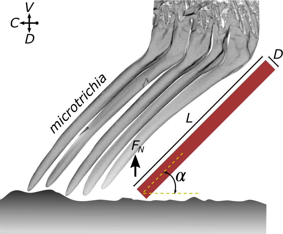
Estimate of the elastic modulus of the microtrichia cuticle needed to maintain tip contact during attachment.
A microtrichium is modelled as a cylinder (length L and diameter D: 6.7 µm and 0.56 µm, respectively) that is loaded with a peak normal force (FN) and that makes tip contact at an angle (40° to 50°). See text for further details on the assumptions and the model.
Figure 8
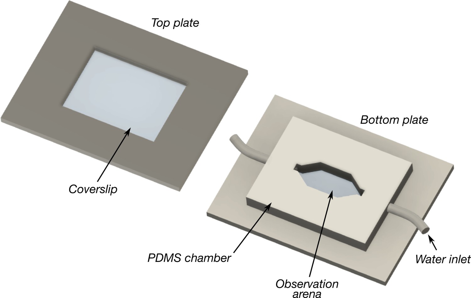
Schematic of the flow chamber used to observe blepharicerid larvae locomoting in fast-flow conditions.
Two to five larvae at a time were added to the observation arena, covered with the top and bottom coverslips and plates, and imaged using interference reflection microscopy. A water pump continuously circulated cooled water at flow rates ranging between approximately 6 and 15 ml/s. Coverslip thickness: 0.16–0.19 mm. Plate dimensions: 100 × 60 mm in length × width. Observation arena dimensions: approximately 16 × 8 mm in width × height. PDMS: polydimethylsiloxane.
Videos
Video 1
Hapalothrix lugubris larvae live on rocks in torrential alpine streams.
Temporarily diverting the flow of water reveals two larvae firmly attached to the rock.
Video 2
Three-dimensional rendering of a Hapalothrix lugubris suction organ based on computed microtomography data.
The video begins with a side view of the organ and its internal structures (see Figure 1c-e). Digital dissections and rendering were made using Drishti (Limaye and Stock, 2012).
Video 3
Suction organ of a Hapalothrix lugubris larva in action, filmed using in vivo interference reflection microscopy and a custom flow chamber.
Note the V-notch opens immediately prior to detachment.
Tables
Table 1
Surface profilometry of test substrates used to assess attachment performance.
| Surface characteristics (mean ± SD) | |||
|---|---|---|---|
| Test surfaces | Ra (µm) | Rq (µm) | PV (µm) |
| Rough surfaces | |||
| Micro-rough(0.05 µm grain size) | 0.32 ± 0.01 | 0.40 ± 0.01 | 4.56 ± 0.22 |
| Coarse-rough(30 µm grain size) | 7.97 ± 0.06 | 10.37 ± 0.08 | 78.82 ± 1.38 |
| Microtextured substrates | |||
| 10 × 10 µm | NA | NA | 2.04 ± 0.18 |
| 3 × 3 µm | NA | NA | 4.48 ± 0.08 |
| 3 × 3 µm | NA | NA | 1.69 ± 0.03 |
-
Ra: average roughness (mean height deviation); Rq: root-mean-squared roughness; PV: maximum peak-to-valley height; NA: not applicable.
Table 2
Shear and normal stress estimates for suction-based attachments of Hapalothrix lugubris and Liponeura cordata.
| Species | Shear stress (kPa) | Normal stress (kPa) | ||||
|---|---|---|---|---|---|---|
| Conservative(mean ± SD) | Conservative(mean ± SD) | n | Conservative(mean ± SD) | Realistic(mean ± SD) | n | |
| Liponeura cordata | 41.2 ± 21.4 | 111 ± 57.5 | 10 | 40.5 ± 27.6 | 120.2 ± 81.9 | 11 |
| Hapalothrix lugubris | 39.3 ± 10.6 | 117 ± 31.4 | 15 | 40.5 ± 27.6 | 71.2 ± 22.2 | 10 |
-
Conservative: contact area based on suction disc, inclusive of the outer fringe layer and all six organs in contact prior to detachment.
-
Realistic: based on three organs in contact immediately prior to detachment and contact areas excluding the outer fringe layer.
-
Table 2—source data 1
Data for Table 2.
- https://cdn.elifesciences.org/articles/63250/elife-63250-table2-data1-v1.csv
Additional files
Download links
A two-part list of links to download the article, or parts of the article, in various formats.
Downloads (link to download the article as PDF)
Open citations (links to open the citations from this article in various online reference manager services)
Cite this article (links to download the citations from this article in formats compatible with various reference manager tools)
Extreme suction attachment performance from specialised insects living in mountain streams (Diptera: Blephariceridae)
eLife 10:e63250.
https://doi.org/10.7554/eLife.63250


