Clustered functional domains for curves and corners in cortical area V4
- Peking University School of Life Sciences, China
- Peking-Tsinghua Center for Life Sciences, China
- IDG/McGovern Institute for Brain Research at Peking University, China
- Key Laboratory of Machine Perception (Ministry of Education), Peking University, China
- The Center for Excellence in Brain Science and Intelligence Technology, State Key Laboratory of Neuroscience, Key Laboratory of Primate Neurobiology, Institute of Neuroscience, Chinese Academy of Sciences, China
- Beijing Normal University Faculty of Psychology, China
Figures
Figure 1 with 3 supplements
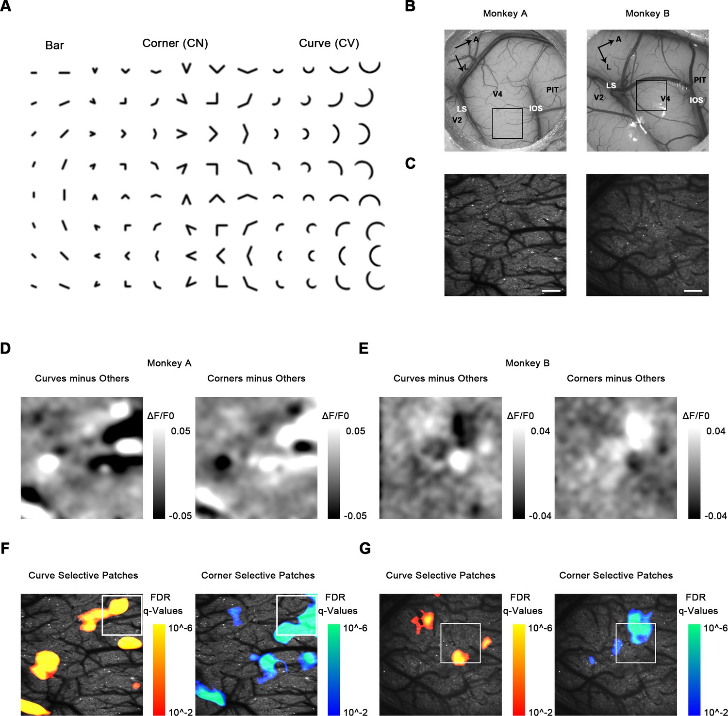
Cortical mapping of curve-biased and corner-biased patches in V4 using a 4× objective lens.
(A) The stimulus set used for initial cortical mapping consisting of bars, corners, and smooth curves. (B) Vascular map. LS: lunate sulcus; IOS: inferior occipital sulcus. The black box indicates the imaging site in each subject. (C) Two-photon fluorescence images of the two monkeys. Scale bar = 400 μm. (D) Left: subtraction map showing curve-selective activation in monkey A, derived by the average response (ΔF/F0) to all curves minus the average response to all other stimuli (corners and bars). Right: subtraction map showing corner-selective activation in monkey A. (E) The equivalent of (D) for monkey B. (F) Left: significant curve patches in monkey A. For each pixel, independent t-tests were performed to compare the responses to all curves against all corners and against all bars. Benjamini-Hochberg procedure was used to compute the pixel FDR (false discovery rate, see Materials and methods). Threshold q = 0.01. The white box indicates the imaging site selected for 16× objective single-cell mapping. Right: significant corner patches in monkey A. (G) The equivalent of (F) for monkey B.
Figure 1—figure supplement 1
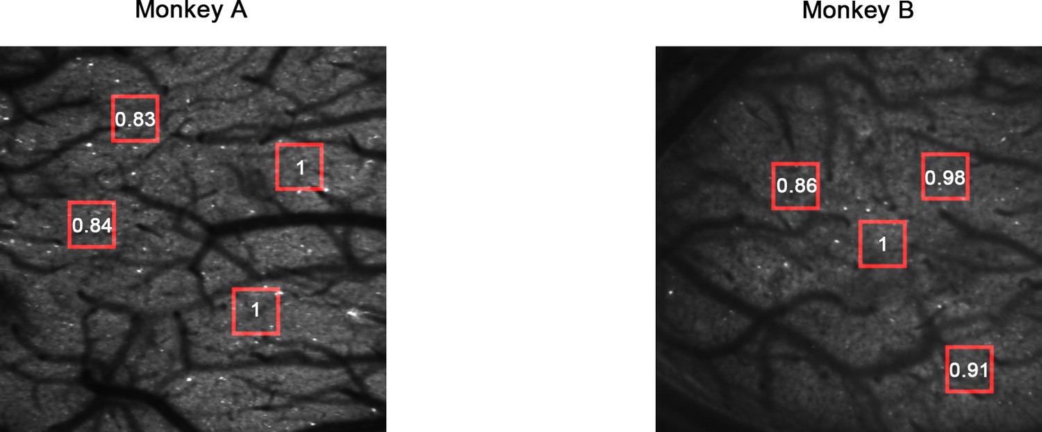
Two-photon fluorescence images.
The numbers indicate the average fluorescence of the areas marked by the red boxes (normalized).
Figure 1—figure supplement 2
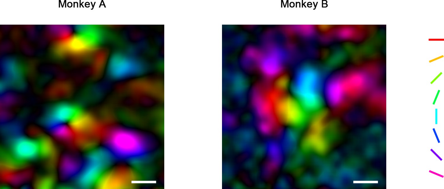
Pseudo-color orientation map obtained by 4× imaging.
Scale bar = 400 μm. For each pixel, the preferred orientation was derived by the vector summation of its responses (Gaussian smoothed ΔF/F0) to eight orientations. Hues in the map indicate the orientations of the sum vectors (preferred orientation), and lightness indicates the length (orientation selectivity). Orientation is organized in linear bands and pinwheels in V4.
Figure 1—figure supplement 3
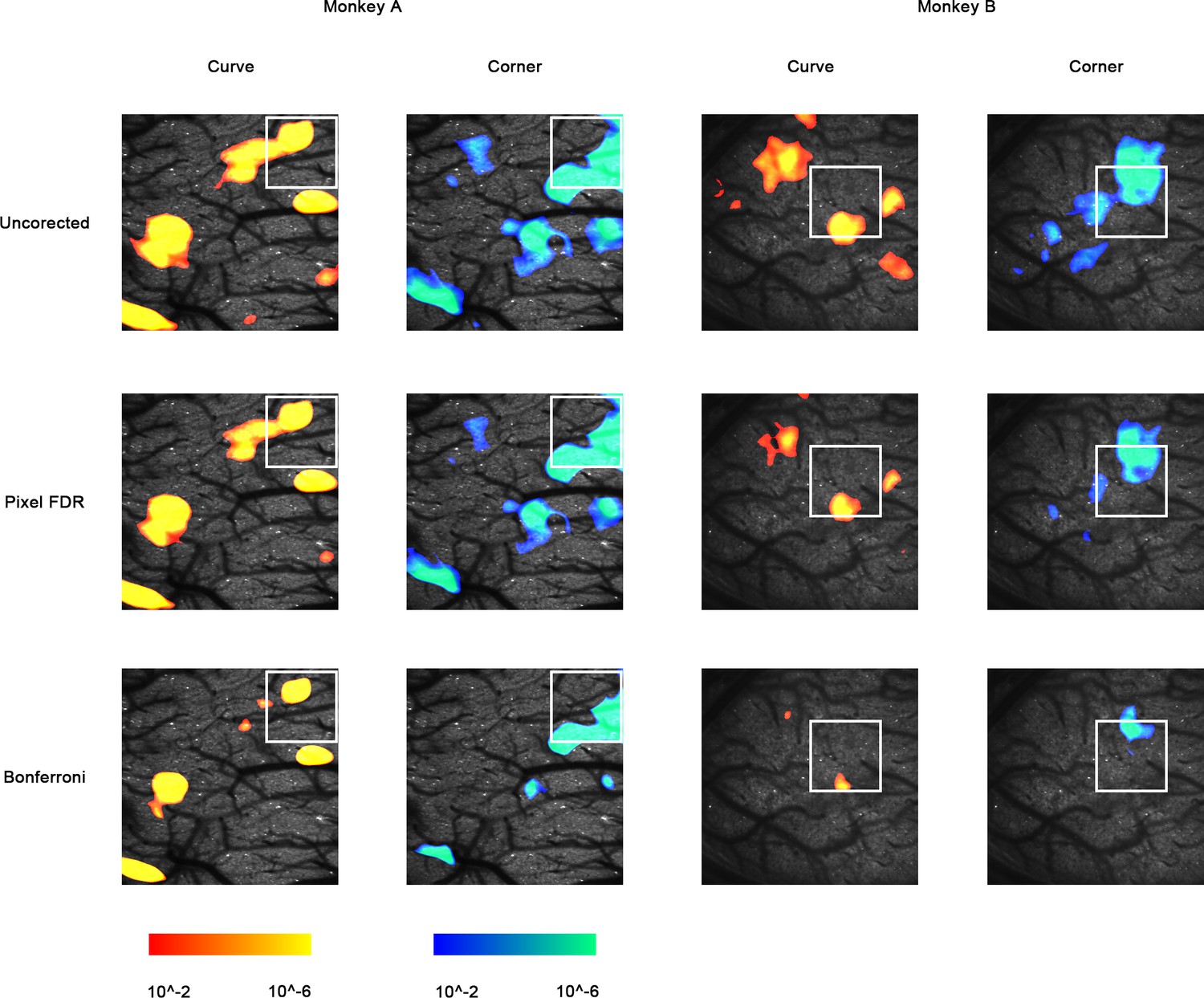
Maps of uncorrected p-values (p<0.01), FDR q-values (q < 0.01), and Bonferroni-corrected p-values (p<0.01), before cluster permutation tests.
Figure 2 with 3 supplements
Single-cell mapping of curve- and corner-selective neurons using a 16× objective lens.
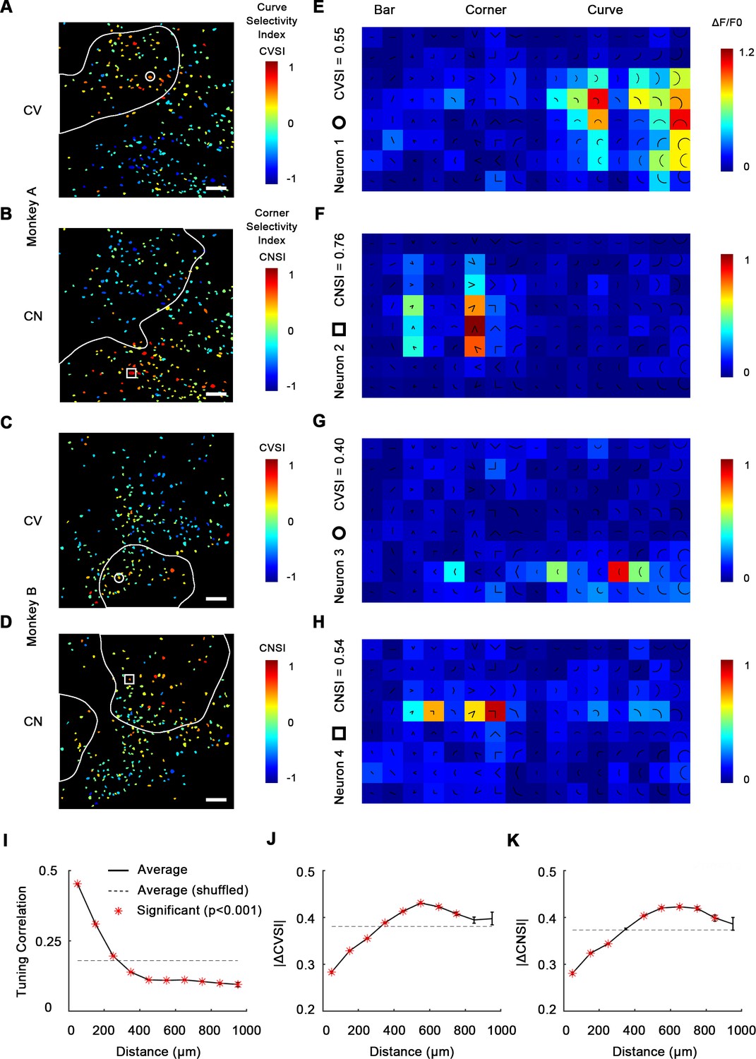
(A) Cell map of curve selectivity index (CVSI). Responsive neurons are labeled at their spatial location and colored according to their CVSI. Neurons with high positive CVSI (high curve preference) were clustered in the upper part of the imaging area. The white line indicates the curve-biased patches derived by 4× imaging (Figure 1E). Scale bar = 100 μm. (B) Cell map of corner selectivity index (CNSI). Neurons with high positive CNSI (high corner preference) were clustered in the lower part of the imaging area. (C, D) Equivalent maps for monkey B. (E–H) Responses of four example neurons preferring curves or corners, their locations labeled in (A–D), respectively. (I) Neuronal pairwise tuning correlation (mean ± SE, averaging all neurons every 100 μm) plotted against spatial distances. The average correlation between different repeats of same neuron is 0.71 (Figure 2—figure supplement 2). The dash curve indicates the average of neurons when shuffled. Significance levels were determined by permutation test. (J) Absolute CVSI value differences (mean ± SE) plotted against distances. (K) Absolute CNSI value differences (mean ± SE) plotted against distances.
Figure 2—figure supplement 1
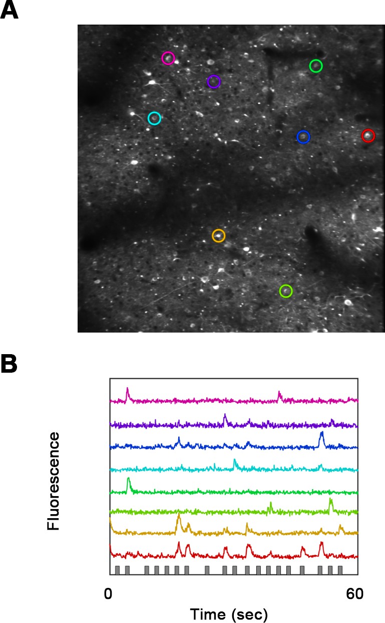
Single-cell resolution fluorecence imge.
(A) Fluorescence image using a 16× objective lens. (B) Raw fluorescence traces of eight neurons (colored circles in A).
Figure 2—figure supplement 2
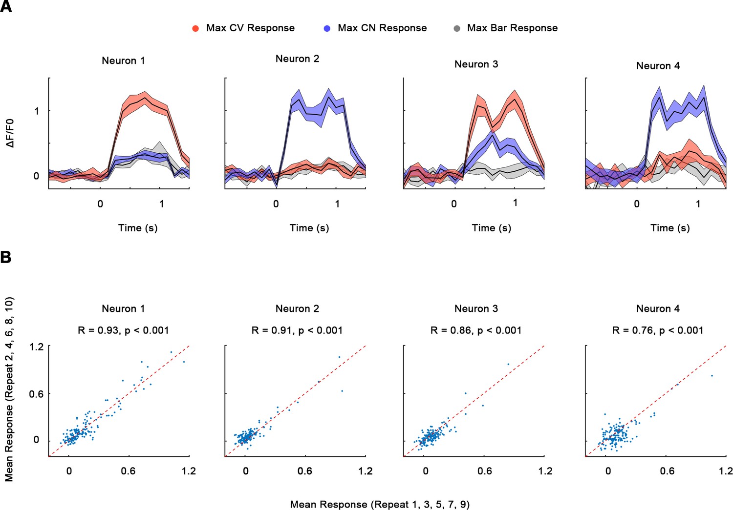
Single-neuron responses.
(A) GCaMP timecourses (ΔF/F0, mean ± SE) of the neurons in Figure 2A–D, each under its optimal curves, corners, and bars. Trials were synchronized so that 0 s indicates the time of stimulus onset. (B) Scatterplots showing average neuronal responses to the stimuli (bars, curves, and corners) in the odd repeats (1, 3, 5, 7, 9) and even repeats (2, 4, 6, 8, 10). The red dash line indicates the y = x line. Pearson correlation R > 0.5 for 474 out of total 535 neurons (88.6%).
Figure 2—figure supplement 3
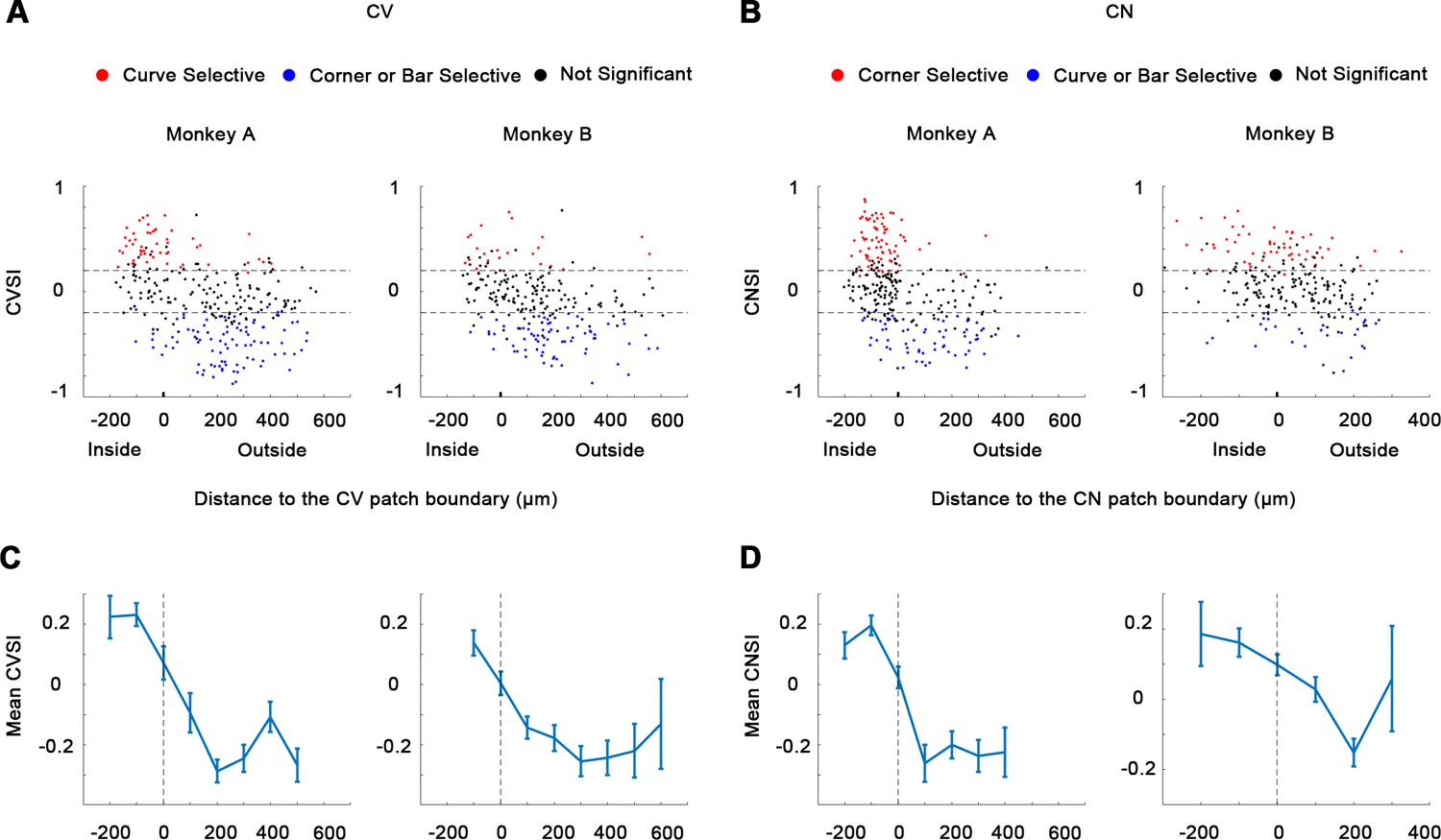
Curve selectivity index (CVSI) and corner selectivity index (CNSI).
(A-B) CVSI and CNSI were tested, comparing the maximum responses to curves against the maximum responses to corners/bars (CVSI), or bars against curves/bars (CNSI). One-way ANOVA, p<0.05, n = 10. (C-D) Average CVSI and CNSI (mean ± SE) plotted against the distances to the CV or CN domain boundary.
Figure 3 with 1 supplement
Combined maps of curve/corner preference.
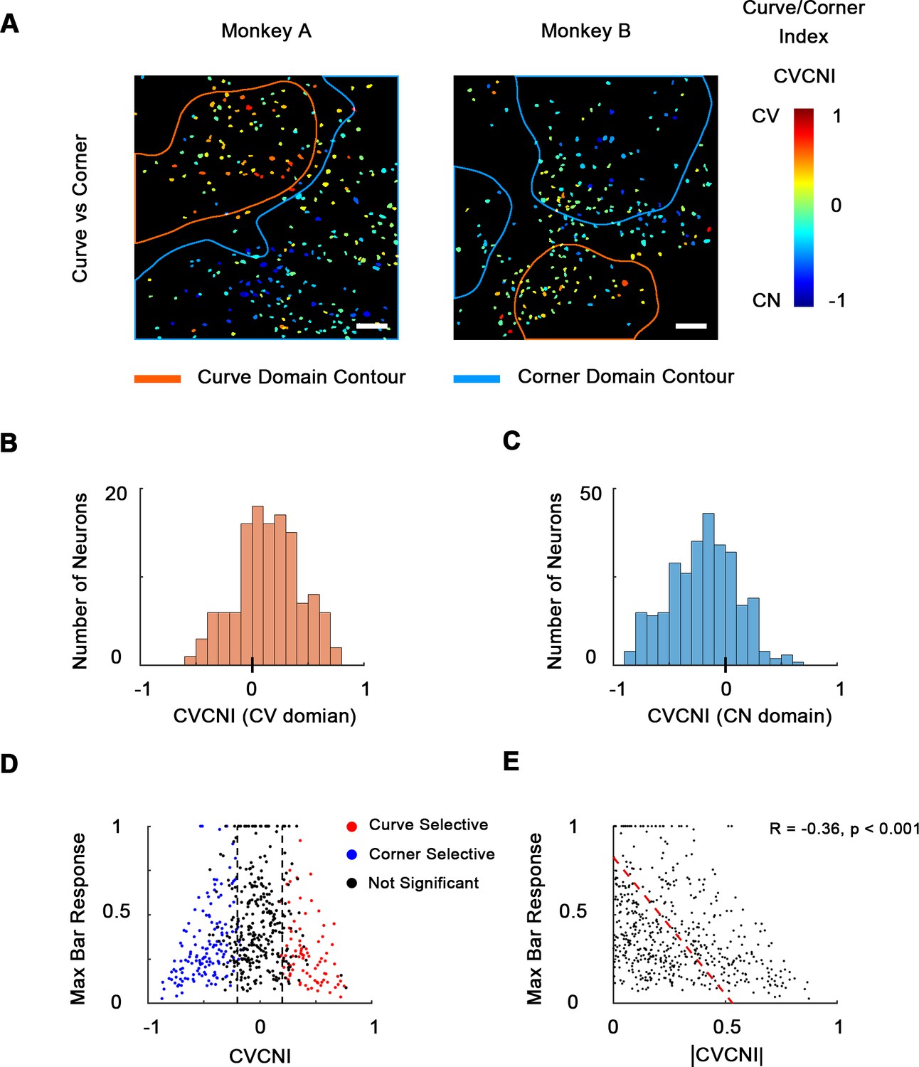
(A) Cell map of curve/corner index (CVCNI). Positive CVCNI indicates preference for curves over corners and vice versa. Curve-selective neurons and corner-selective neurons are spatially clustered. Scale bar = 100 μm. (B) Histogram of CVCNI for neurons located within the curve-biased domains. Mean = 0.15 ± 0.03 S.E. (C) Histogram of CVCNI for neurons located within the corner-biased domains. Mean = −0.20 ± 0.02 S.E. (D) Scatterplot of maximum responses to bars (normalized to 0–1 by the maximum responses to all contour features) against CVCNI. Red dots indicate neurons showing significant preference for curves (ANOVA p<0.05, n = 10) and blue for corners. The majority of neurons (74.5%) with CVCNI < −0.2 or >0.2 were significantly selective. Neurons that highly preferred curves over corners or corners over curves did not respond strongly to single-orientated bars. (E) Neurons’ maximum bar responses were negatively correlated with the absolute values of CVCNI. The red line represents the linear regression line.
Figure 3—figure supplement 1
Neurons’ tuning to curves and corners.
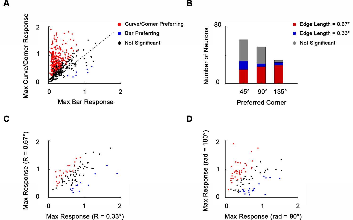
(A) Scatterplot of neurons’ maximum responses to curves and corners against bars. 65.7% of 535 neurons recoded in the imaging area showed significantly stronger responses to curves and corners over bars (n = 10, one-way ANOVA, p<0.05). Only 1.5% showed significantly stronger responses to bars over curves and corners. (B) Size and separation angle selectivity of corner-selective neurons (147 out of 535 neurons that significantly preferred corners over curves). 62, 52, and 33 neurons preferred 45°, 90°, and 135° corners, respectively. 70 neurons significantly preferred big corners (bar length = 20 pixels, 0.67°), and 20 significantly preferred small corners (bar length = 10 pixels, 0.33°). 57 neurons were size invariant. (C) Scatterplot of maximal responses to large (R = 20 pixels, 0.67°) against small curves (R = 10 pixels, 0.33°). 84 out of 535 neurons that significantly preferred curves over corners are included, 22 of which significantly preferred big curves and 12 preferred small curves (n = 10, one-way ANOVA, p<0.05). 50 neurons were size invariant. (D) Scatterplot of neurons’ maximum responses to long curves (rad = 180°) against short curves (rad = 120°). Neurons included are the same as (B). 35 neurons significantly preferred long curves and 18 preferred small curves. 31 neurons were radian invariant.
Figure 4 with 1 supplement
Curve-preferring neurons are selective for smoothness.
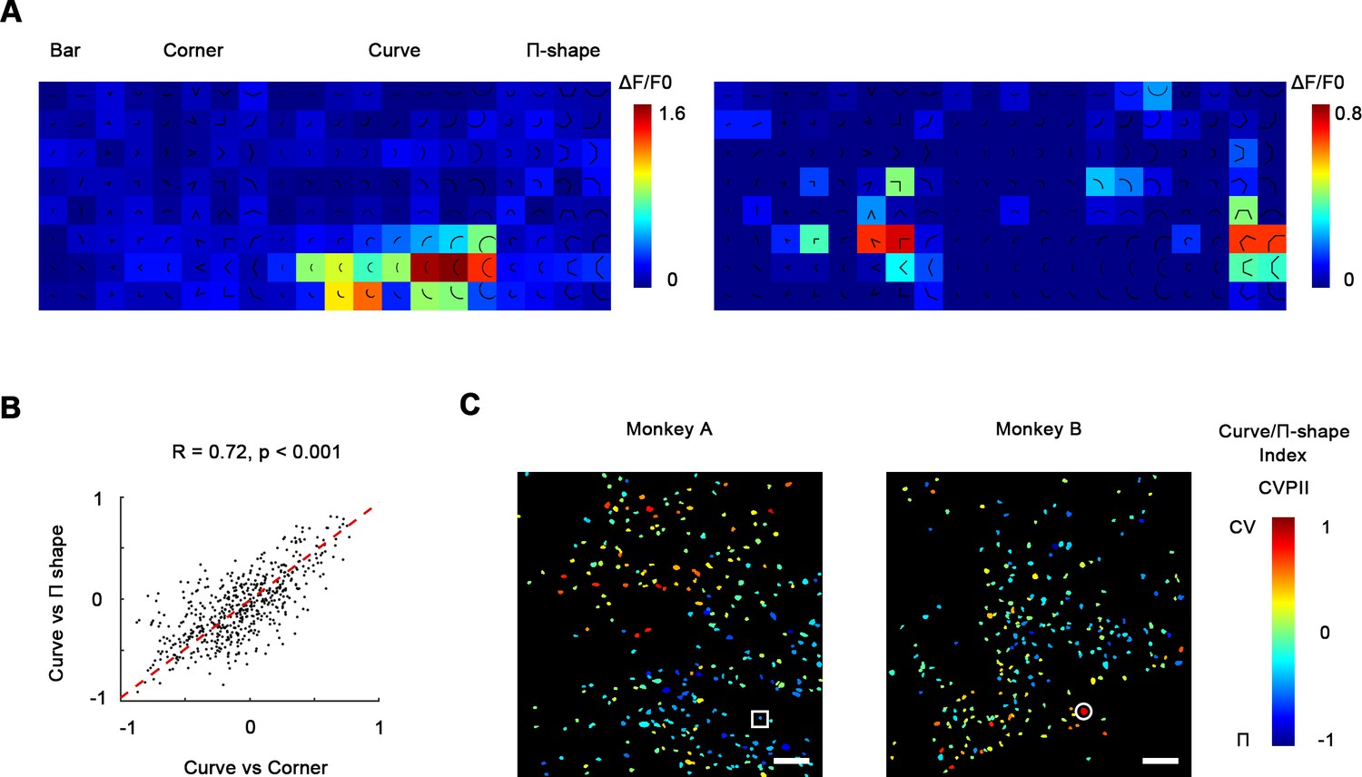
(A) Left: responses of an example curve preferring neurons to bars, corners, smooth curves, and Π-shape stimuli, indicated by the white circle in (C). The neurons responded strongly to smooth curves but not to Π-shape, which highly resemble curves despite lack of smoothness. Right: an example neuron responding to rectilinear corners and Π-shapes, indicated by the white square in (C). (B) Scatterplot of curve/corner index (CVCNI) against curve/Π-shape index (CVPII), which characterizes neuronal preference for smooth curves over Π-shape stimuli. The red dash line represents the linear regression line. The two values were highly correlated, indicating that neurons preferring curves over corners also preferred curves over Π-shape stimuli. (C) Cell map of CVPII. Scale bar = 100 μm. Neurons are clustered similarly to CVCNI (Figure 3A).
Figure 4—figure supplement 1
K-means clustering analysis.
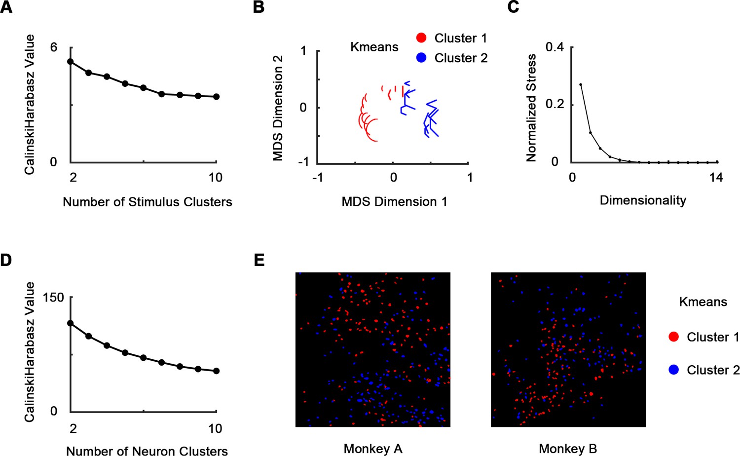
535 neurons’ responses to 20 stimulus forms (two bars, eight curves, six corners, and four Π-shapes, each at eight orientations) were used. (A) We clustered the stimulus forms using population response vector (see Materials and methods). Cluster number = 2 according to Calinski–Harabasz criterion. (B) The two clusters were visualized using multi-dimensional scaling (MDS). (C) The normalized stress of MDS. Stress = 0.104 when dimensionality = 2. (D) We clustered the neurons using neuron response vector (see Materials and methods). Cluster number = 2 according to Calinski–Harabasz criterion. (E) The two neural clusters are also spatially clustered and are consistent with curve/corner index (CVCNI) maps (Figure 3A).
Figure 5 with 2 supplements
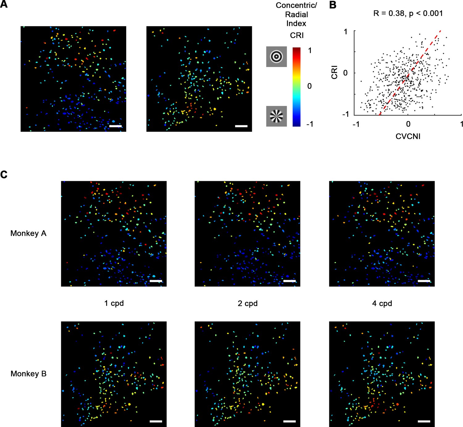
Concentric and radial gratings preference.
(A) Cell map of concentric/radial index (CRI). Positive CRI indicates preference for concentric over radial gratings and vice versa. Concentric grating-selective neurons and radial grating-selective neurons are spatially clustered, and the overall distribution was consistent with curve/corner selectivity (Figure 3A). Scale bar = 100 μm. (B) Scatterplot of curve/corner index (CVCNI) against CRI, which were positively correlated. The red dash line represents the linear regression line. (C) CRI cell maps at spatial frequencies of 1, 2, and 4 cycles/° (cpd). The map structure remained consistent.
Figure 5—figure supplement 1

Responses to Cartesian, concentric, and radial gratings.
(A) Responses (ΔF/F0, mean ± SE) of three example neurons to grating stimuli. (B) Scatterplot of neurons’ maximum responses to concentric and radial gratings against Cartesian gratings. 48.4% of 535 neurons recoded in the imaging area showed significantly stronger responses to concentric or radial gratings (red, n = 11 for monkey A, and n = 8 for monkey B, one-way ANOVA, p<0.05). Only 2.2% showed significantly stronger responses Cartesian gratings (blue). Black indicates no significant preference (p≥0.05). (C) Histogram of neurons’ optimal Cartesian gratings spatial frequencies. Neuronal responses to its optimal Cartesian gratings at spatial frequencies of 1, 2, and 4 cycle/° were compared using one-way ANOVA (p<0.05).
Figure 5—figure supplement 2
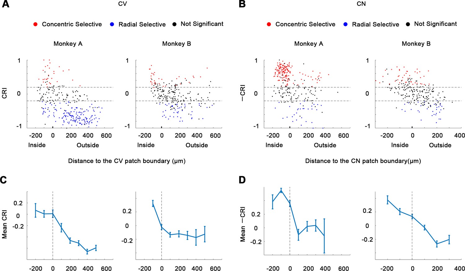
Concentric/radial index (CRI).
(A-B) CRI were tested, comparing the maximum responses to concentric gratings against the maximum responses to radial gratings. One-way ANOVA, p<0.05, n = 10. (C-D) Average CRI and -CRI (mean ± SE) plotted against the distances to the CV or CN domain boundary.
Author response image 1
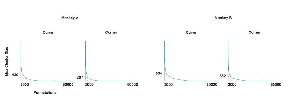
The null distribution of cluster permutation test (in descending rank order).
The 3000th (top 0.05) maximum cluster size (in pixels) is chosen as threshold.
Author response image 2

Scatterplot showing the maximum response to 60° curves against the maximum response to bars of the curve selective neurons.
Tables
Key resources table
| Reagent type (species) or resource | Designation | Source or reference | Identifiers | Additional information |
|---|---|---|---|---|
| Strain, strain background (Macaca mulatta) | Macaca mulatta | Beijing Prima Biotech Inc | http://www.primasbio.com/en/Home | |
| Recombinant DNA reagent | AAV9.Syn.GCaMP6f.WPRE.SV40 | Penn Vector Core | CS1001 | |
| Recombinant DNA reagent | AAV1.Syn.GCaMP5G.WPRE.SV40 | Penn Vector Core | V4102MI-R | |
| Software, algorithm | MATLAB R2018b | MathWorks | https://www.mathworks.com | |
| Software, algorithm | Code for data analysis | This paper | https://github.com/RJiang1994/macaque-v4-2P (Jiang, 2021 copy archived at swh:1:rev:57dfeac5e81b91c93ef0687f8cf04010d3f47f8c) |
Additional files
Download links
A two-part list of links to download the article, or parts of the article, in various formats.
Downloads (link to download the article as PDF)
Open citations (links to open the citations from this article in various online reference manager services)
Cite this article (links to download the citations from this article in formats compatible with various reference manager tools)
Clustered functional domains for curves and corners in cortical area V4
eLife 10:e63798.
https://doi.org/10.7554/eLife.63798


