Squamation and scale morphology at the root of jawed vertebrates
- School of Earth Sciences and Engineering, Nanjing University, China
- Key Laboratory of Vertebrate Evolution and Human Origins of Chinese Academy of Sciences, Institute of Vertebrate Paleontology and Paleoanthropology, Chinese Academy of Sciences, China
- CAS Center for Excellence in Life and Paleoenvironment, China
Figures
Figure 1
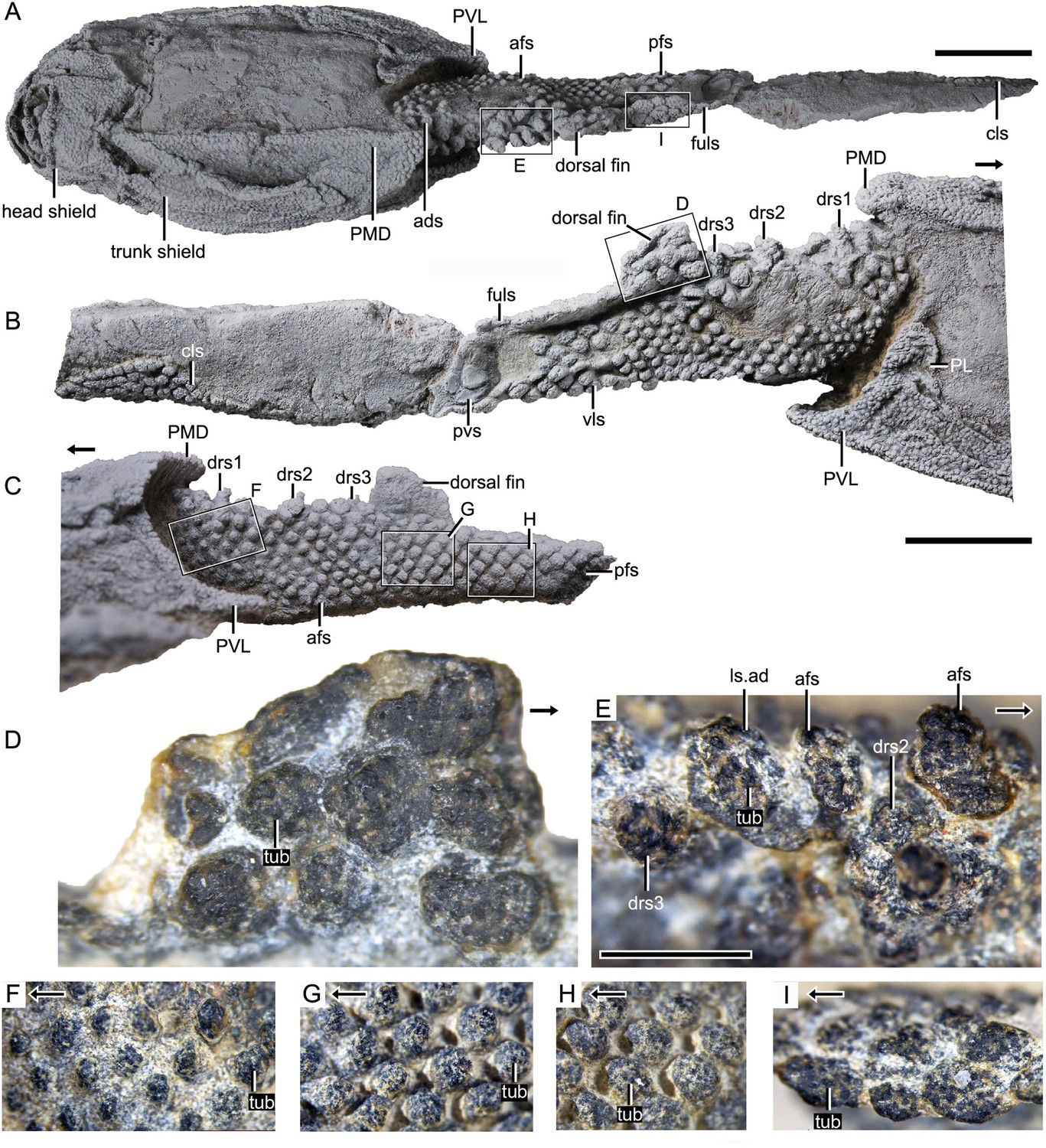
Photograph of Parayunnanolepis xitunensis, holotype IVPP V11679.1.
(A) Dorsal view. (B) Right lateral view. (C) Left lateral view. (D–I) Magnified images of rectangles in (A–C). (D) Dorsal fin in left lateral view. (E) Predorsal scales in dorsal view. (F–H) Flank scales (fs) in lateral view. (I) Postdorsal scales in dorsal view. The black arrow indicates the anterior direction. PL, posterior lateral plate; PVL, posterior ventrolateral plate; other abbreviations see text. A–C share a scale bar of 5 mm, D–I of 1 mm.
Figure 2
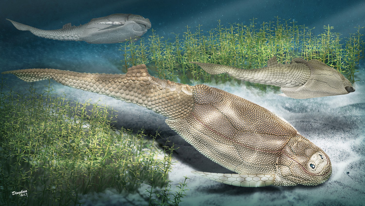
Life reconstruction of Parayunnanolepis xitunensis, drawn by Dinghua Yang.
Figure 3 with 2 supplements

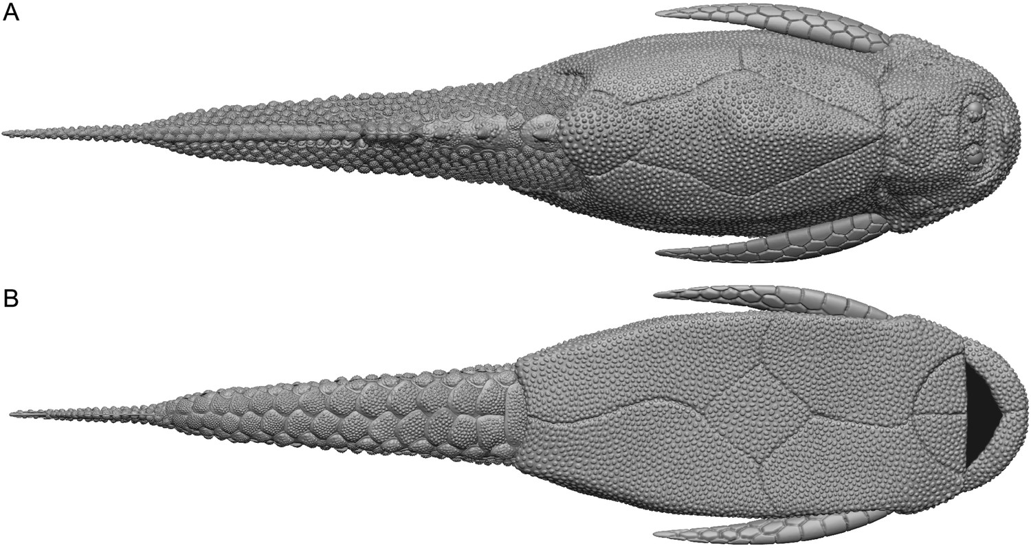
Reconstructed squamation of P.xitunensis based on CT scanning, IVPP V11679.1.
(A–D) Squamation in (A) right lateral, (B) left lateral, (C) anterior, and (D) dorsal views. (E) Posterodorsal fulcral scales in ventral side. (F) Interpretative diagram of the dorsal fin scales, showing their contact relationships. (G) Dorsal fin scales in left lateral view. (H) Dorsal scales in right lateral view. (I–J) Anterior dorsal scales in (I) dorsal and (J) left lateral views. (K) Morphotype 6–7 scales on the right side in CT reconstruction (K1) and cross-section diagram (K2), showing the trajectory and profile of the lateral line groove. (L) Morphotype 6 scales on the left side. The black and red arrows indicate the anterior and dorsal directions, respectively. Dotted lines indicate the levels of vertical sections shown in (K2). PDL, posterior dorsolateral plate; other abbreviations see text and Figure 1. Scale bars equal to 2 mm.
Figure 3—figure supplement 1
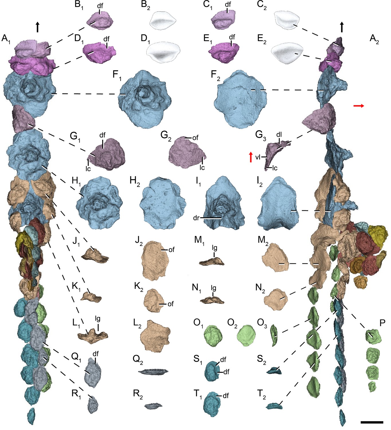
Dorsal scales of Parayunnanolepis xitunensis (IVPP V11679.1) based on CT scanning.
(A) Dorsal squamation in (A1) dorsal and (A2) left lateral views. (B–E) Anterior dorsal scale in (B1–E1) dorsal and (B2–E)2 ventral views. (F, H and I) First, second and third dorsal ridge scale in (F1, H1 and I1) dorsal and (F2, H2 and I2) ventral views. (G) Anterior dorsolateral scale in (G1) dorsal, (G2) ventral and (G3) posterior views. (J–N) anterodorsal lateral line scale in (J1–N1) posterior and (J2–N2) ventral views. (O) Posterodorsal lateral line scale in (O1) dorsal, (O2) ventral and (O3) left lateral views. (P) Posterodorsal lateral line scale preserved on the left side in dorsal view. (Q–T) Posterodorsal fulcral scale in (Q1–T1) dorsal, (Q2–R2) mesial and (S2–T2) posterior views. The black and red arrows indicate the anterior and dorsal directions, respectively. of, overlapping field; other abbreviations see text. Scale bar equals to 1 mm.
Figure 3—figure supplement 2
Dorsal fin scales of Parayunnanolepis xitunensis (IVPP V11679.1) based on CT scanning.
(A1, C1–H1, J1–N1) Dorsal view. (A2, C2–H2, J2–N2) Ventral view. (B and I) Lateral view. The black arrow indicates the anterior direction. Scale bar equals to 1 mm.
Figure 4 with 1 supplement
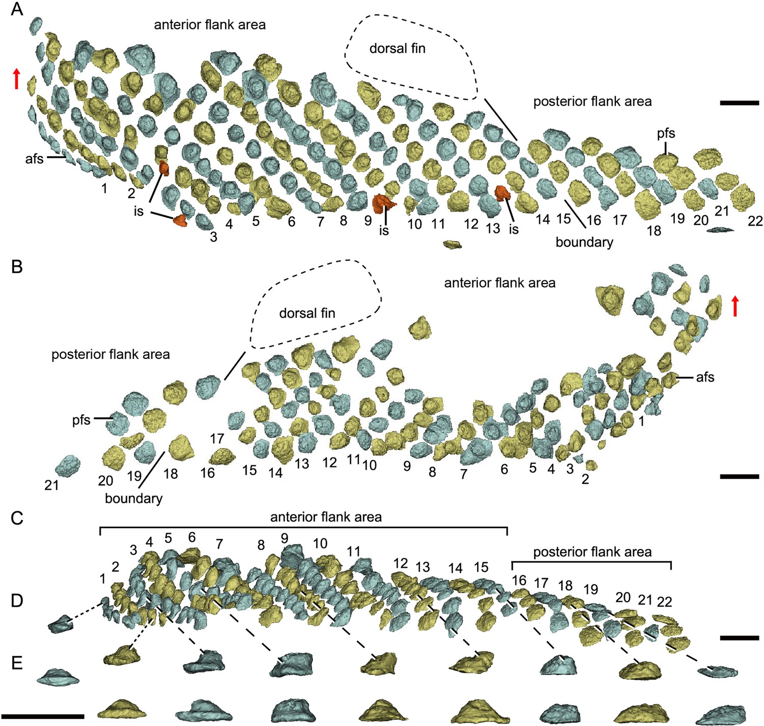
Reconstructed flank squamation of Parayunnanolepis xitunensis based on CT scanning, holotype IVPP V11679.1.
(A) Left flank scales in lateral view. (B) Right flank scales in lateral view. (C) Left flank scales in ventral view. (D–E) A series of flank scales in (D) ventral and (E) anterior views, showing the anterior–posterior gradation of scales. The boundaries between the anterior and posterior flank areas are indicated by a solid line, which represents the extend line of the posterior edge of the dorsal fin. The red scales shown in (A) are interspersed scales (is). The red arrow indicates the dorsal direction. Scale bars equal to 1 mm.
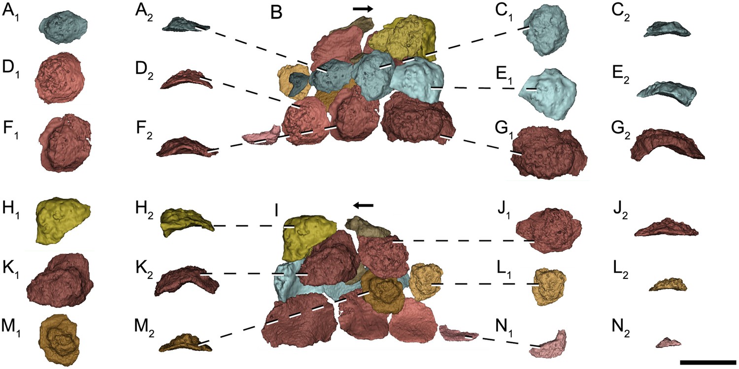
Figure 4—figure supplement 1
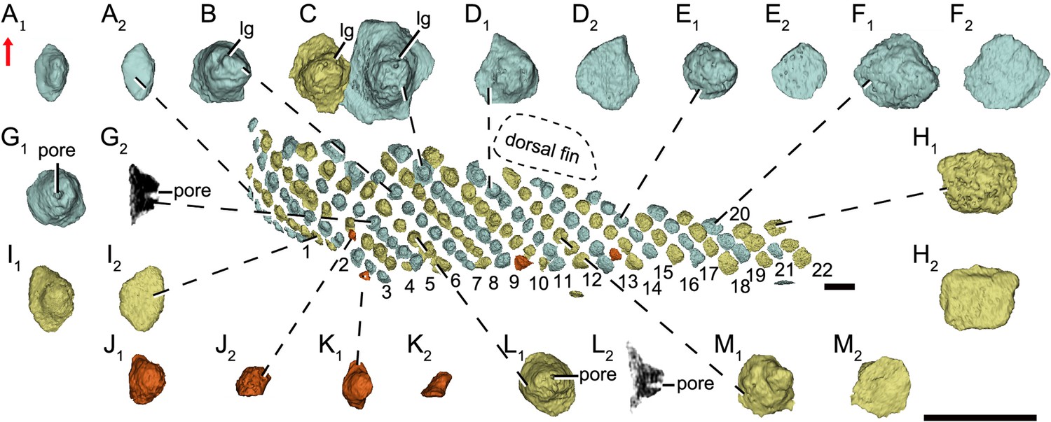
Flank scales on the left side of Parayunnanolepis xitunensis (IVPP V11679.1) based on CT scanning.
(A–E, (G), I–M) Anterior flank scales in (A1–E1, (G1), I1–M1) dorsal and (A2–E2, (G2), I2–M2) ventral views. (F and H) Posterior flank scales in (F1 and H1) dorsal and (F2 and H2) ventral views. The red arrow indicates the dorsal direction. Scale bars equal to 1 mm.
Figure 5 with 1 supplement
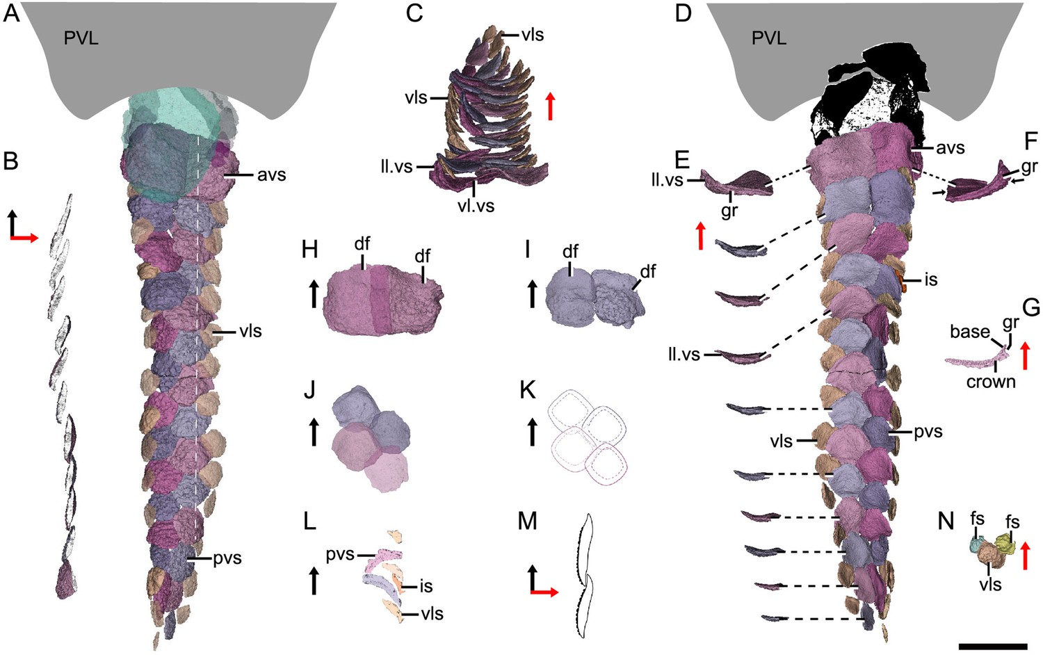
Reconstructed ventral squamation of Parayunnanolepis xitunensis based on CT scanning, holotype IVPP V11679.1.
(A) Ventral scales in ventral view. (B) Virtual axial section of the ventral scutes at the level indicated by the white dotted line in (A). (C) Ventral scutes in anterior view. (D) Ventral scales in dorsal view. (E) A series of ventral scutes in posterior view. (F) The first right ventral scute in posterior view. (G) Virtual axial section of the scale in (F). (H–I) Anterior ventral scutes in (H) first and (I) second rows in ventral views. (J–K) Reconstruction and interpretative reconstructions of the posterior ventral scutes in the fourth and fifth rows in ventral view, respectively. (L) Virtual sagittal section of the additional scale and its surrounding scales. (M) Schematic diagram of the articulated way between ventral scutes in the front and back rows. (N) Ventrolateral scale and its surrounding flank scales. The black and red arrows indicate the anterior and dorsal directions, respectively. Scale bar equal to 2 mm.
Figure 5—figure supplement 1

Ventral scales of Parayunnanolepis xitunensis (IVPP V11679.1) based on CT scanning.
(A), and (C–G) Anterior ventral scutes in (A1), and (C1–G1) dorsal and (A2), and (C2–G2) ventral views. (B) Ventral squaqmation in ventral view. (H–I) Ventrolateral scale in (H1–I1) dorsal, (H2–I2) ventral and (H3–I3) posterior views. (J–N) Posterior ventral scutes in (J1–N1) dorsal and (J2–N2) ventral views. The black and red arrows indicate the anterior and dorsal directions, respectively. Scale bar equals to 1 mm.
Figure 6 with 1 supplement
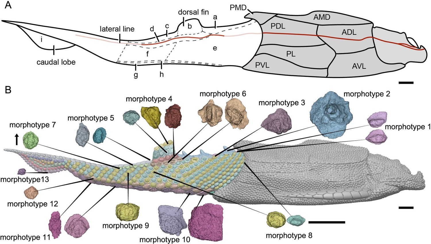
Reconstruction of Parayunnanolepis xitunensis in lateral view.
(A) Squamation model showing division of areas. (B) 3D model by Dinghua Yang, showing distribution of scale morphotypes. Small letters in (A) represent the (a) predorsal, (b) dorsal fin, (c) posterodorsal, (d) dorsolateral, (e) anterior flank, (f) posterior flank, (g) ventral, (h) ventrolateral and (i) caudal lobe areas. Scales from CT reconstruction in (B) share the same scale bar and are aligned towards the anterior direction, as indicated by the black arrow. Each morphotype is represented by a typical scale or scales with the most disparity within the morphotype. Deep and light red lines represent the exact and inferred trajectory of the lateral line, respectively. ADL, anterior dorsolateral plate; AMD, anterior median dorsal plate; AVL,anterior ventrolateral plate; other abbreviations see text and Figures 1 and 3. Scale bars equal to 2 mm.
Figure 6—figure supplement 1
Reconstruction of Parayunnanolepis xitunensis by Dinghua Yang.
(A) Dorsal view. (B) Ventral view.
Figure 7 with 1 supplement
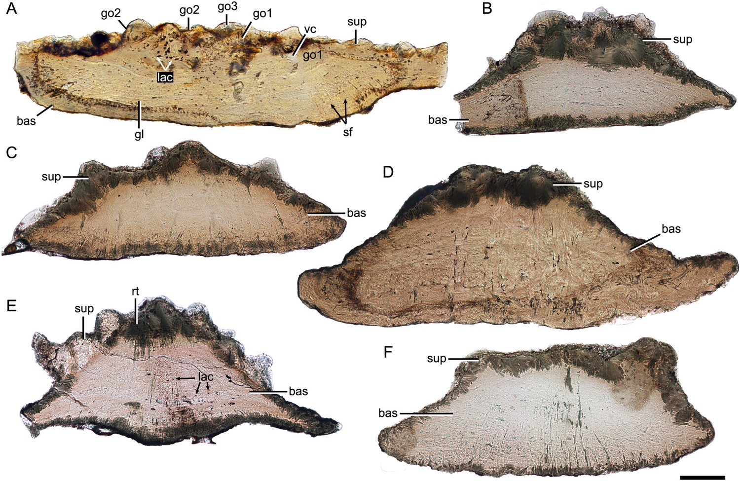
Thin sections through yunnanolepidoid scales.
(A) IVPP V28642. (B) IVPP V28643. (C) IVPP V28644. (D) IVPP V28645. (E) IVPP V28646. (F) IVPP V29647. Scale bar equal to 100 μm.
Figure 7—figure supplement 1
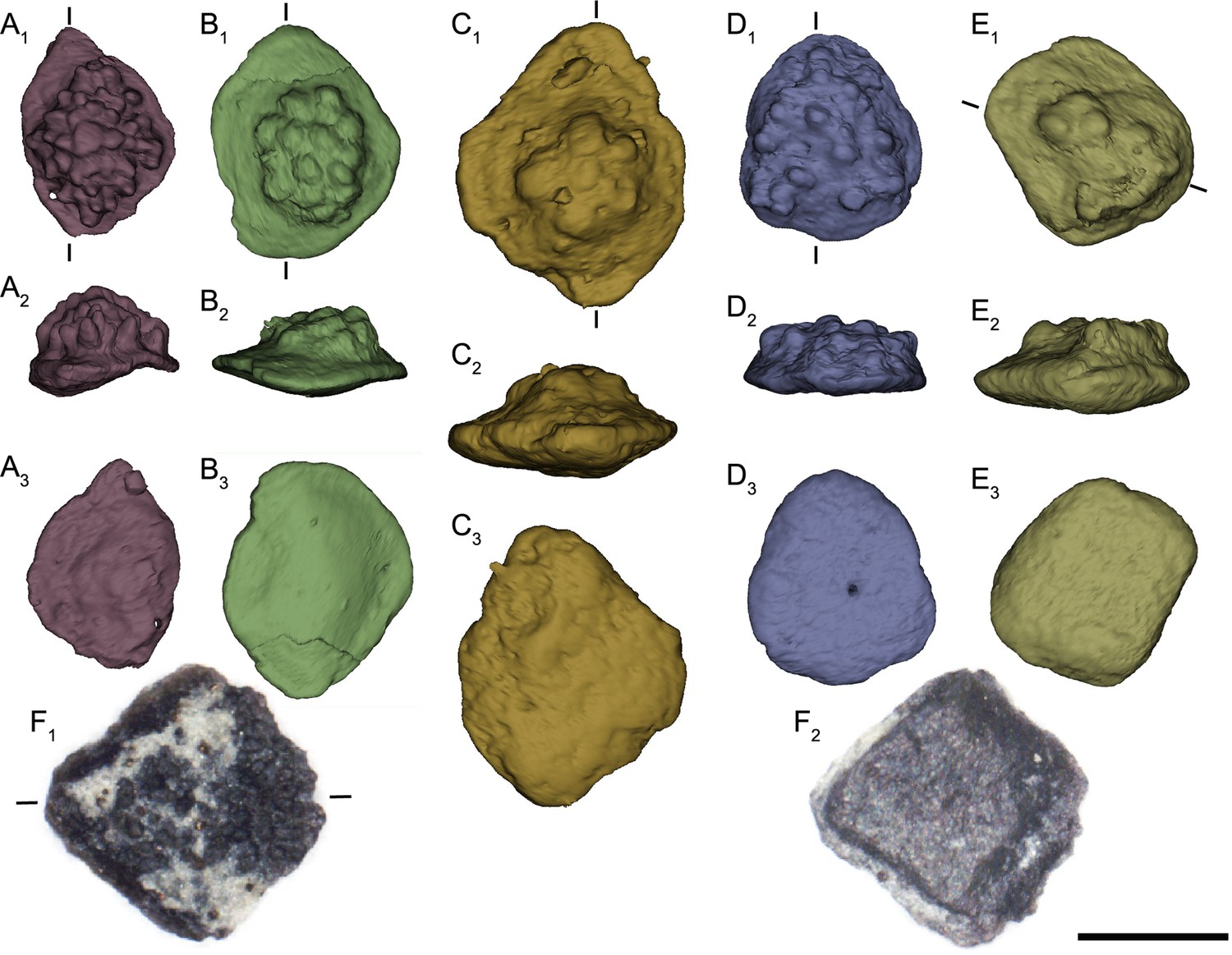
Yunnanolepidoid scales.
(A–E) Reconstruction of IVPP V28642–V28647 based on CT scanning. (A) V28646. (B) V28643. (C) V28645. (D) V28644. (E) V28647. (F) V28642. (A1–F1) Dorsal view. (A2–E2) Lateral view. (A3–E3, F2) Ventral view. Approximate planes of dorso-ventral vertical ground sections are indicated by short lines. Scale bar equals to 500 μm.
Figure 8
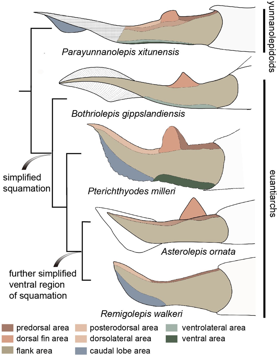
Evolution of squamation patterns of the post-thoracic region in antiarchs.
Redrawn from the source illustrations of Long and Werdelin, 1986 for Bothriolepis gippslandiensis, Hemmings, 1978 for Pterichthyodes milleri, Ivanov et al., 1996 for Asterolepis ornata, and Johanson, 1997 for Remigolepis walkeri.
Figure 9
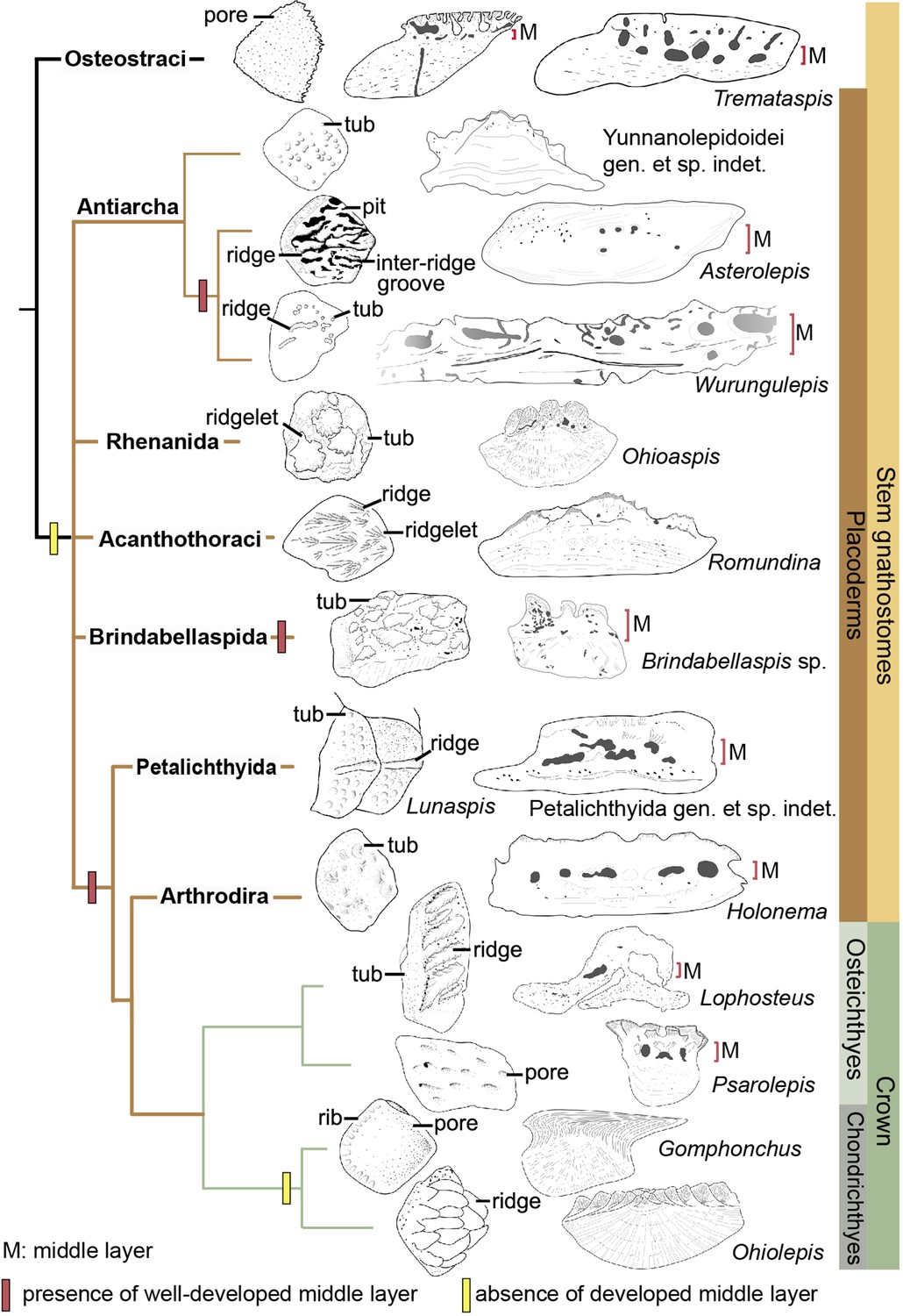
Sculpture pattern and histology of scales among gnathostomes.
The phylogenetic hypothesis is after Zhu et al., 2016 as it accords with most of the recent hypotheses about the interrelationships of early jawed vertebrates. Taxon drawings are redrawn from source illustrations of Märss et al., 2015 and Qu et al., 2015a for Tremataspis, Burrow and Turner, 1999 and Ivanov et al., 1996 for Asterolepis, Burrow and Turner, 1998 and Young, 1990 for Wurungulepis, Giles et al., 2013 and Rücklin and Donoghue, 2015 for Romundina, Burrow and Turner, 1999 for Ohioaspis, Burrow and Turner, 1999 for Lunaspis, Burrow and Turner, 1998 for Brindabellaspis, Burrow et al., 2000 for Petalichthyida gen. et sp. indet., Trinajstic, 1999 for Holonema, Jerve et al., 2016 and Gross, 1969 for Lophosteus,Qu et al., 2017 for Psarolepis, Gross, 1971 for Gomphonchus, and Gross, 1973 for Ohiolepis. Terminology of scale sculpture follows Märss et al., 2015. The first column shows scales in dorsal view; the second column shows scales in vertical ground section.
Additional files
Download links
A two-part list of links to download the article, or parts of the article, in various formats.
Downloads (link to download the article as PDF)
Open citations (links to open the citations from this article in various online reference manager services)
Cite this article (links to download the citations from this article in formats compatible with various reference manager tools)
Squamation and scale morphology at the root of jawed vertebrates
eLife 11:e76661.
https://doi.org/10.7554/eLife.76661


