Optogenetic activation of visual thalamus generates artificial visual percepts
- Department of Medicine, University of Fribourg, Switzerland
- Department of Neurobiology, School of Basic Medical Sciences, Nanjing Medical University, China
- Department of Material Science and Engineering, Northwestern University, United States
- Querrey Simpson Institute for Bioelectronics, Northwestern University, United States
Figures
Figure 1 with 3 supplements
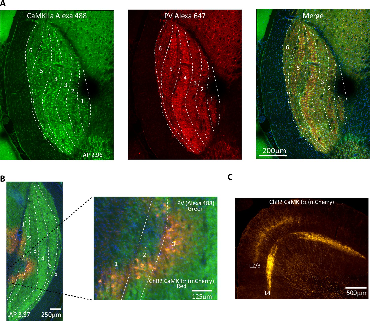
Validation of CaMKIIα and ChR2 expression in tree shrew lateral geniculate nucleus (LGN).
(A) Confocal images of tree shrew LGN immunostained for both CaMKIIα (left) and parvalbumin (center), with the merge shown at right. Dashed lines indicate laminar boundaries. Note that CaMKIIα is found throughout LGN laminae as well as in the interlaminar zones. AP coordinates are from the interaural line. (B) Epifluorescent image immunostained for parvalbumin, green, revealing LGN layers, and showing viral expression (mCherry, red) in LGN layers 1–3. (C) Axonal projection patterns in V1 from viral transfected cells in the LGN. Note prominent projections to both granular and superficial layers.
Figure 1—figure supplement 1
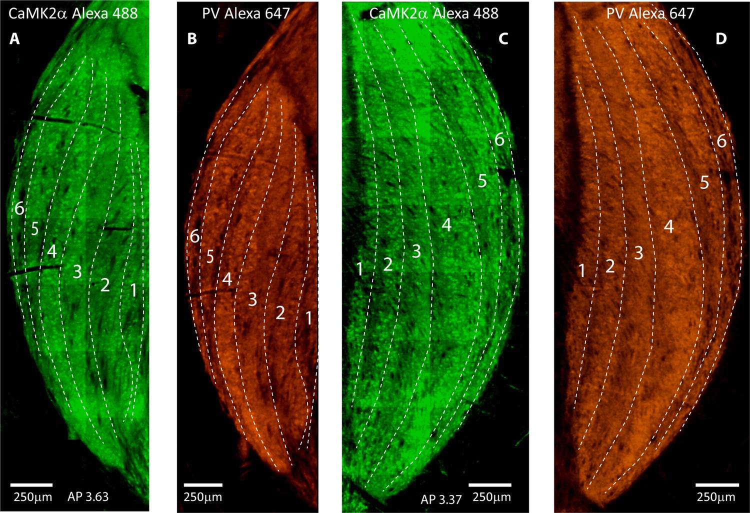
Immunohistochemistry for CaMKIIa and parvalbumin (PV) in lateral geniculate nucleus (LGN).
(A, B) Epifluorescent images showing immunostaining for CaMKIIα (A) and parvalbumin (B) in the LGN, right hemisphere. (C, D) Same as (A, B) but for a different animal and from the left hemisphere. Dashed lines indicate laminar boundaries. AP coordinates are from the interaural line.
Figure 1—figure supplement 2
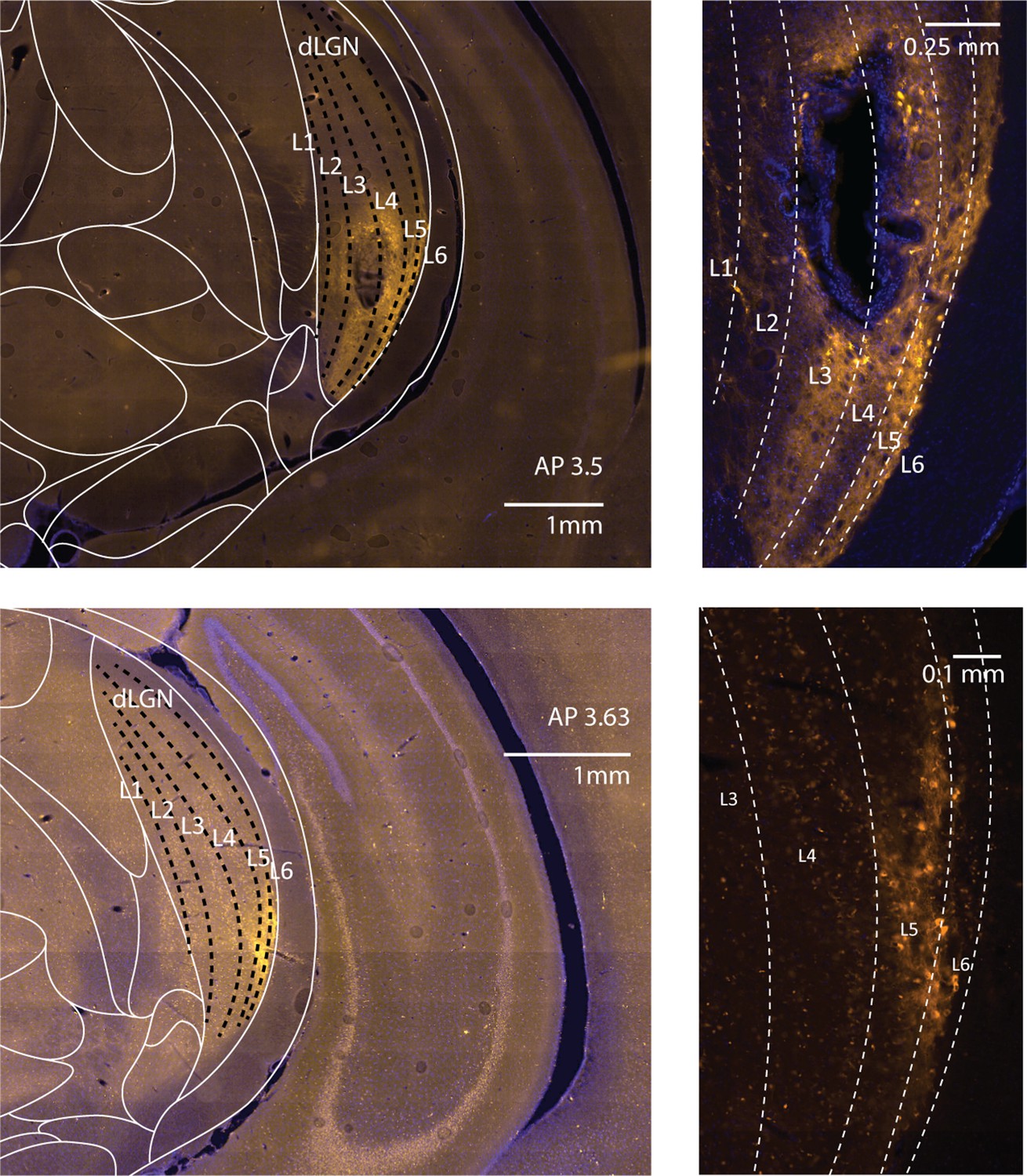
ChR2 expression in CaMKIIα neurons in tree shrew lateral geniculate nucleus (LGN).
(Top left) Epifluorescent image taken from behavioral animal 1809 at AP 3.5 (interaural) showing viral expression and probe track in the ventral aspect of the LGN. (Top right) Zoom of the image at left showing transfected cell bodies. (Bottom left) Same as top left but at AP 3.63 in a different animal, with viral expression restricted to the ventral lateral aspects of the LGN. (Bottom right). Zoom of the image at left. Dashed lines indicate laminar boundaries.
Figure 1—figure supplement 3

ChR2 expression in CaMKIIα thalamocortical axons in tree shrew V1.
(A, B) Epifluorescent images of primary visual cortex taken from two different animals receiving viral injections in dorsal lateral geniculate nucleus (dLGN). Note strong labeling in layer 4 in both animals, with particularly strong labeling also of layers 2/3 in (A). (C) Top and bottom show zoomed images of panels (A) and (B), respectively.
Figure 2 with 1 supplement
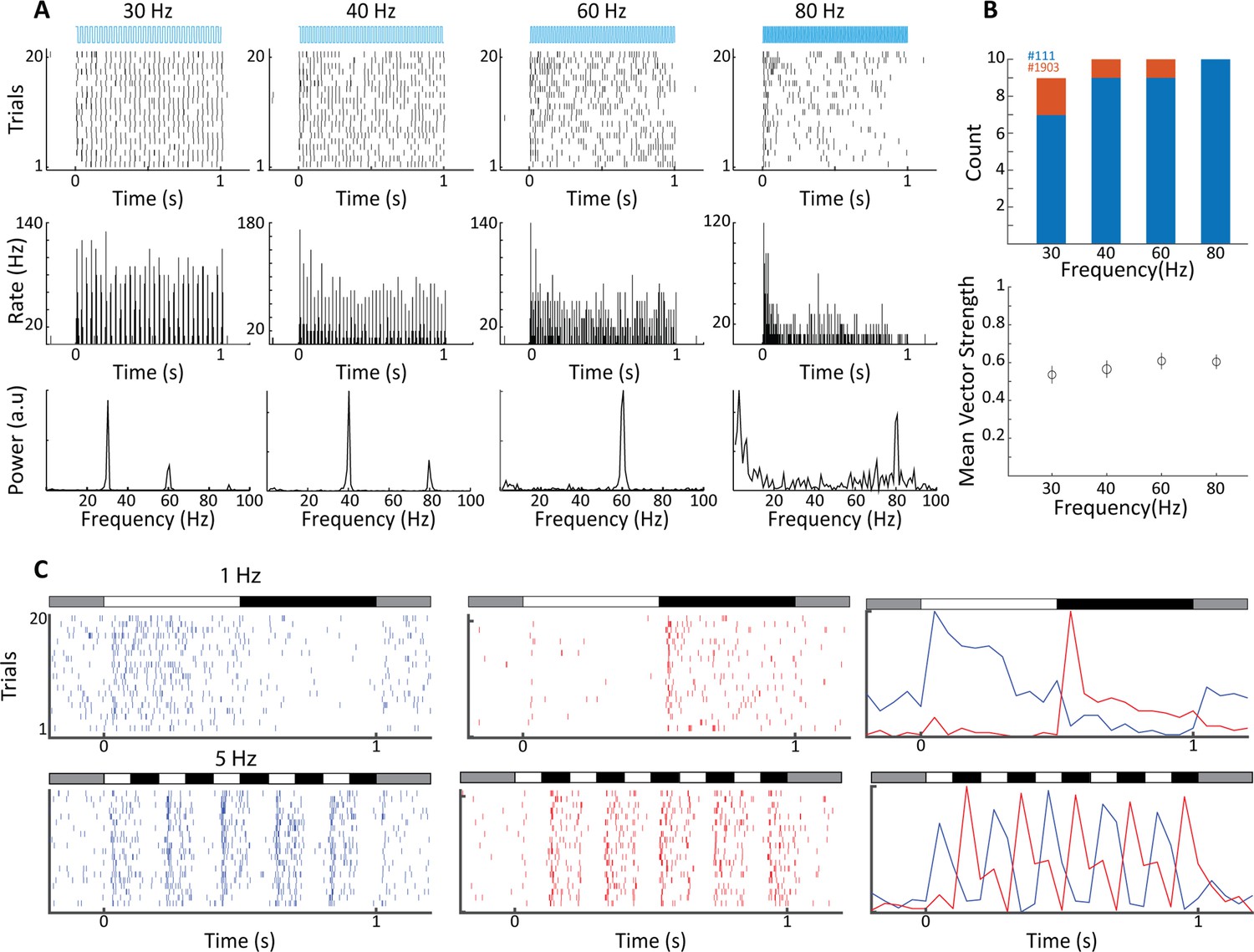
Electrophysiological validation of functional ChR2 expression in lateral geniculate nucleus (LGN) CaMKIIα neurons.
(A) Raster plots (top) show 20 trials of responses of a single LGN neuron in animal #111 to different frequencies of 473 nm blue laser activation. Each vertical bar represents a single spike. Peri stimulus time histograms (PSTHs) (5 ms bin size) and Fast Fourier Transforms (FFTs) of the same spike trains are shown at center and bottom, respectively. For this, cell phase locking disappeared at the highest frequency, 80 Hz. (B) Top shows a histogram of the number of significantly phase-locked neurons, as determined by vector strength, at the four flicker frequencies for two animals (#111 blue, #1903 orange). Bottom is the mean vector strength for the phase-locked neurons at the four flicker frequencies; error bars represent SEM. (C) Raster plots (left and center) and PSTHs (right) reveal both ON- and OFF-type visual responses at sites nearby to laser stimulation for both 1 Hz top and 5 Hz bottom, stimulation frequencies. Bars at the top of each plot indicate the contrast condition, with gray being the background illumination.
Figure 2—figure supplement 1
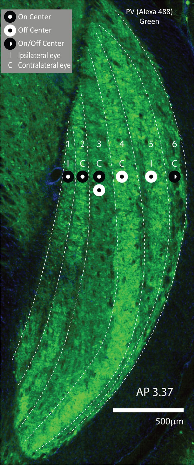
Tree shrew lateral geniculate nucleus (LGN), functional organization.
Epifluorescent image of the tree shrew LGN immunostained for parvalbumin (green) to reveal layers. There are four layers corresponding to the contralateral eye, 2, 3, 4, and 5, and two layers corresponding to the ipsilateral eye, 1 and 5. Layers 1–3 have ON center-type receptive fields, whereas layers 4 and 5 have OFF center receptive fields with antagonistic surrounds. Layer 3 contains cells with both ON- and OFF center receptive fields, and layer 6 contains cells with an ON/OFF center and an OFF surround. Dashed white lines delineate laminar borders.
Figure 3 with 1 supplement
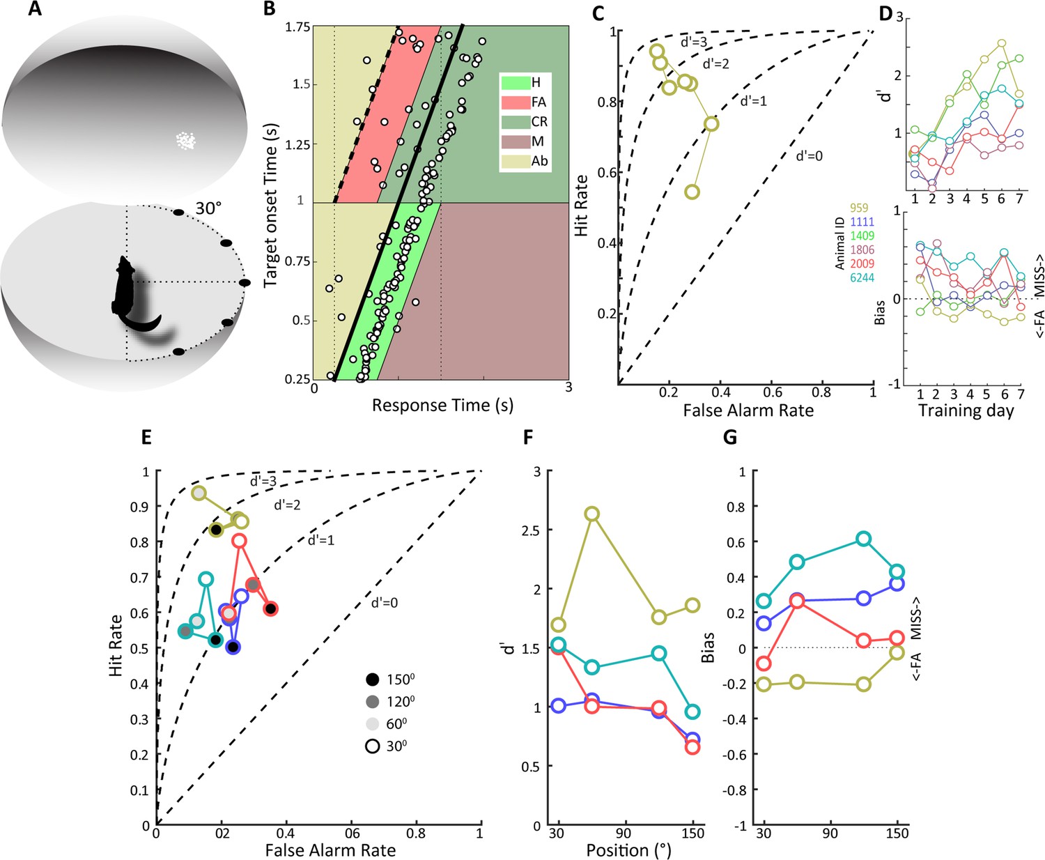
Detection of a visual moving dot stimulus.
(A) Illustration of the experimental setup. Animals were trained to poke their nose into a response port at the center of a sphere and remain there until the appearance of a 2⁰ patch of moving white dots appeared in the field of view. (B) Plotted is the behavior of an animal, #959, that has acquired the task when phosphene stimuli were presented at the center of the field of view. Target onset is indicated by the thick, oblique black line. The light green trapezoid depicts the area during which responses were considered hits, and the orange trapezoid depicts the area of false alarms. H, hit; FA, false alarm; CR, correct rejection; M, miss; Ab, abort. (C) False alarm vs. hit rates are plotted over training days for the same animal as in (B). Note that as learning progresses the hit rate increases as the false alarm rate declines. (D) At top, d' values over training days are plotted for all animals, showing increased sensitivity over training days. Different colors denote different animals, and the color scheme is maintained throughout subsequent figures to facilitate comparison of individual animal performance on different tasks. (Bottom) Bias values for the same animals over training days. Note that bias values below zero indicate more false alarms and those above zero indicate more misses. (E) False alarm vs. hit rates are plotted for all animals for phosphene like moving dot visual stimuli presented at different positions relative to the center of the field of view, indicated by grayscale fill. (F) d’ values as a function of stimulus position for the four animals tested. (G) Bias values for the four animals at the different stimulus locations.
Figure 3—figure supplement 1

Reaction times and d’ over training days for visual detection experiment.
(A) Histogram of response latencies for each animal over the course of 7 d of training on the visual detection task. Graphs are stacked for easier visualization, black: day 1; red: day 7. (B) Mean response latencies over training days revealing different trends across animals, e.g., tree shrew 959 showing trend toward reduced latency with training, whereas tree shrew 1111 shows an increase. (C) d’ values shown for reference (same as Figure 3D) documenting successful task acquisition.
Figure 4 with 2 supplements
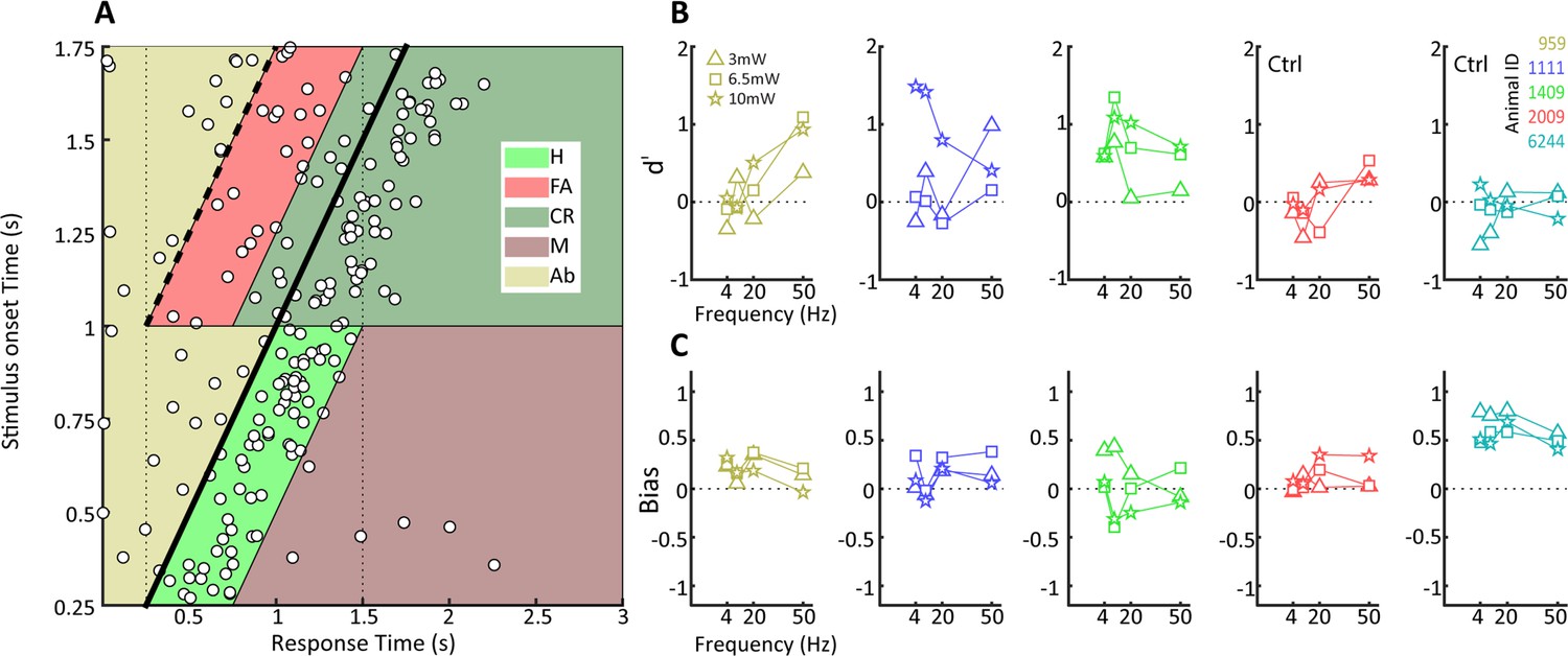
Behavioral detection of optogenetic activation of lateral geniculate nucleus (LGN) CaMKIIα neurons.
(A) As Figure 2B, but for an animal, #1111, detecting blue LED activation of CaMKIIα neurons in the LGN. Note that while the animal can clearly perform the task, detection performance is more variable than for the visual stimulus. (B) d' values at the three LED intensities used are plotted for each animal at four stimulation frequencies (4, 10, 20, and 40 Hz). Ctrl indicates control animals. (C) Same as (B) but for bias scores.
Figure 4—figure supplement 1

Maximum d’ in visual vs. optogenetic detection.
Shown are the maximum d’ values achieved by animals in the visual detection task vs. the optogenetic detection task. Maximum values consider all frequencies and amplitudes used in the optogenetic detection task.
Figure 4—figure supplement 2
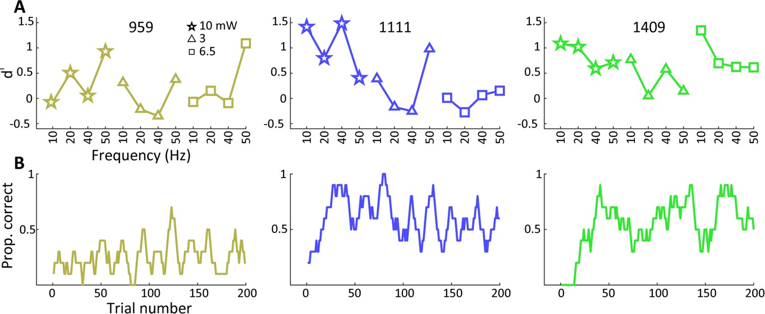
Sequence of behavioral training.
(A) Behavioral performance on the optogenetic lateral geniculate nucleus (LGN) detection experiment using multiple frequencies and amplitudes, with results shown in serial order as the daily experiments were conducted in each animal. (B) Performance assessment during the first optogenetic LGN detection experiment (frequency 10 Hz at 10 mW) for each animal. The raw proportion of correct and rewarded trials smoothed by 10 trial convolution is shown including aborted trials. The results reveal that animals 1111 and 1409 tended to readily generalize from previous visual to optogenetic detection, whereas animal 959 showed some evidence of within-session improvement in performance.
Figure 5
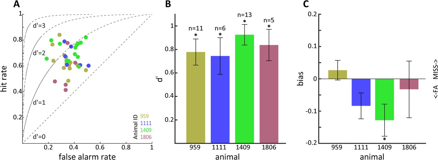
Sensitivity to optogenetic activation of lateral geniculate nucleus (LGN) CaMKIIα neurons.
(A) Hit vs. false alarm rates for multiple sessions. (B) Mean d' calculated from (A) for each animal; error bars reflect SEM and * indicates p<0.05. (C) Same as (B) but for bias scores; note that animal 1409 showed significant bias for false alarms.
Figure 6
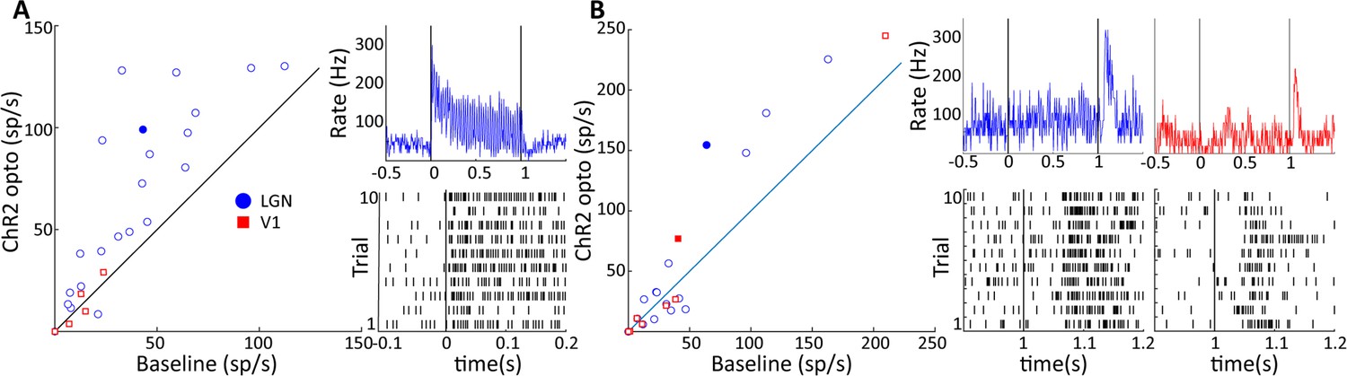
Two response motifs in lateral geniculate nucleus (LGN) and V1 following optogenetic excitation of LGN CaMKIIα neurons.
(A) and (B) show, respectively, sustained, low latency-type responses and those showing only ‘OFF’-type responses in LGN (blue) and V1 (red). (A, left) Scatter plot comparing the firing rate of significantly modulated neurons in LGN and V1 during a baseline period and during 40 Hz optogenetic activation of the LGN. (A, right) PSTH top and raster plot bottom of an example LGN neuron, filled blue circle in (A), in response to 40 Hz blue laser activation of the LGN. Each vertical line in the raster plot corresponds to the time of one spike. (B) Same as (A), but for V1 and LGN neurons showing only ‘OFF’-type responses. Example neurons shown in right panels correspond to the filled blue circle, and filled red square for LGN and V1, respectively.
Figure 7
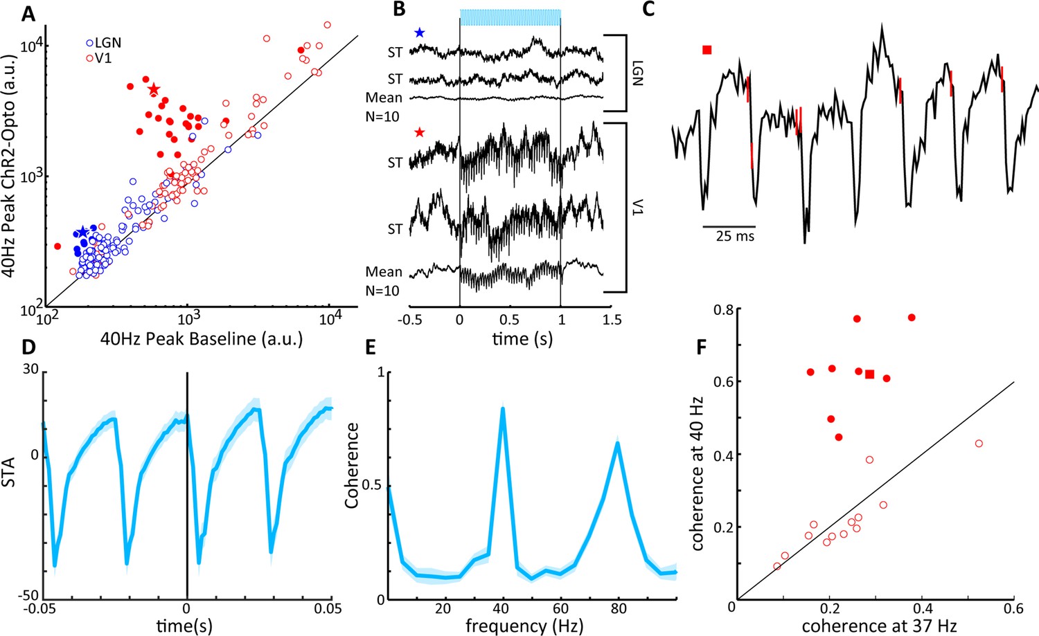
V1 local field potentials (LFPs) show temporal coherence with laser-induced spiking in lateral geniculate nucleus (LGN).
(A) Scatter plot shows the magnitude of the spectral peak at the frequency of LGN laser stimulation (40 Hz) for baseline and LGN stimulation conditions, LGN (blue), V1 (red). Filled circles represent LFP locations showing a significant increase in power at the stimulation frequency. (B) Two single-trial traces (ST) and the mean of 10 trials of LFPs in LGN (top) and V1 (bottom) during 40 Hz laser stimulation of the LGN. Example traces correspond to the star symbols in (A). (C) LGN spikes (red vertical lines) are superimposed upon the V1 LFP during a single trial of 40 Hz laser activation of LGN. Note that spiking in the LGN is quickly followed by a large depth negative deflection in the V1 LFP. (D) Spike-triggered average of the V1 LFP with spiking in the LGN. (E) Spike field coherence between spiking activity in the LGN and the V1 LFP showing high coherence at the stimulation frequency, 40 Hz. (F) Coherence at the stimulation frequency (40 Hz) is compared to coherence at a shoulder frequency, 37 Hz, for all V1 LFPs showing significant modulations in (A). Filled symbols reflect significant differences, and the square symbol represents the example in (C).
Figure 8
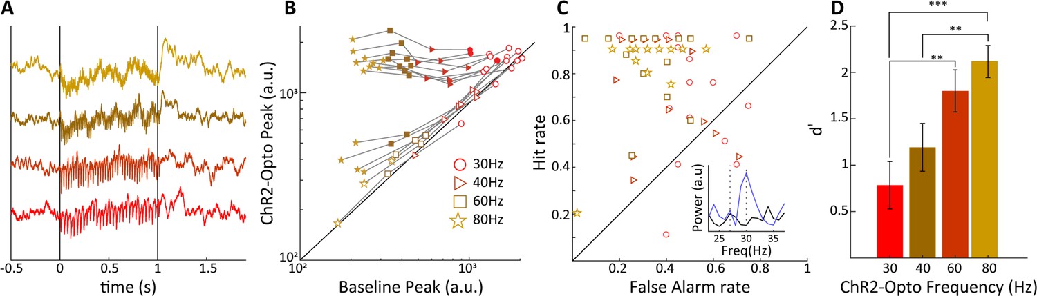
Sensitivity of V1 local field potentials (LFPs) are frequency dependent.
(A) V1 LFPs averaged over 20 trials at the four stimulation frequencies, 30, 40, 60, and 80 Hz, from bottom to top. (B) The magnitude of the spectral peak at the four stimulation frequencies during baseline vs. lateral geniculate nucleus (LGN) laser stimulation conditions. Note that the filled symbols indicate a significant effect of optogenetic stimulation. (C) Hit vs. false alarm rates, see text, for all V1 recording sites are plotted for each frequency of laser stimulation. Inset shows an example FFT during baseline (black) and laser stimulation (blue) during 30 Hz laser stimulation of the LGN. (D) Average V1 LFP sensitivity, d', at the four laser stimulation frequencies. Note the monotonic increase in sensitivity with frequency. Error bars reflect SEM.
Tables
Table 1
Summary of participation of tree shrews in behavioral tasks.
| Tree shrew | Visual detection | Spatial generalization | Optogenetic detection multiple parameters | Optogenetic detection multiple parameters control animals | Optogenetic detection fixed parameters |
|---|---|---|---|---|---|
| Figure panels | Figure 3C and D | Figure 3E–G | Figure 4B | Figure 4B | Figure 5A–C |
| 959 | x | x | X | x | |
| 1111 | x | x | X | x | |
| 1409 | x | X | x | ||
| 1806 | x | x | |||
| 2009 | x | x | x | ||
| 6244 | x | x | x |
Table 2
Serial order of frequency and amplitude values for experiment with multiple parameters.
| Amplitude (mW) | 10 | 10 | 10 | 10 | 3 | 3 | 3 | 3 | 6.5 | 6.5 | 6.5 | 6.5 |
| Frequency (Hz) | 10 | 20 | 4 | 50 | 10 | 20 | 4 | 50 | 10 | 20 | 4 | 50 |
Table 3
Summary of electrophysiological recordings.
| Tree shrew | Total MUA and LFP recordings LGN 40 Hz | Significant MUA entrainment at 30/40/60/80 Hz LGN | Significant 40 Hz ‘ON’ and ‘OFF’ responses in LGN | Significant 40 Hz LFP entrainment in V1 | Significant LFP entrainment at 30/40/60/80 Hz in V1 |
|---|---|---|---|---|---|
| Figure panel | Figure 2 | Figure 6A/B | Figure 7A | Figure 8B | |
| 207 | 17 | Not studied | 8/5 | 1 | Not studied |
| 1503 | 47 | Not studied | 4/2 | 3 | Not studied |
| 1903 | 30 | 2/1 / 1/0 | 1/2 | 12 | 1/0/2/3 |
| 111 | 17 | 7/9 / 9/10 | 9/7 | 13 | 2/9/9/10 |
| Total | 111 | 9/10 / 10/10 | 22/16 | 29 | 3/9/11/13 |
-
LFP, local field potential; LGN, lateral geniculate nucleus; MUA, multi-unit activity.
Additional files
Download links
A two-part list of links to download the article, or parts of the article, in various formats.
Downloads (link to download the article as PDF)
Open citations (links to open the citations from this article in various online reference manager services)
Cite this article (links to download the citations from this article in formats compatible with various reference manager tools)
Optogenetic activation of visual thalamus generates artificial visual percepts
eLife 12:e90431.
https://doi.org/10.7554/eLife.90431


