Using synchronized brain rhythms to bias memory-guided decisions
- Department of Psychological and Brain Sciences, University of Delaware, United States
- Stony Brook University, United States
- Neuroscience Program, Lafayette College, United States
Figures
Figure 1 with 4 supplements
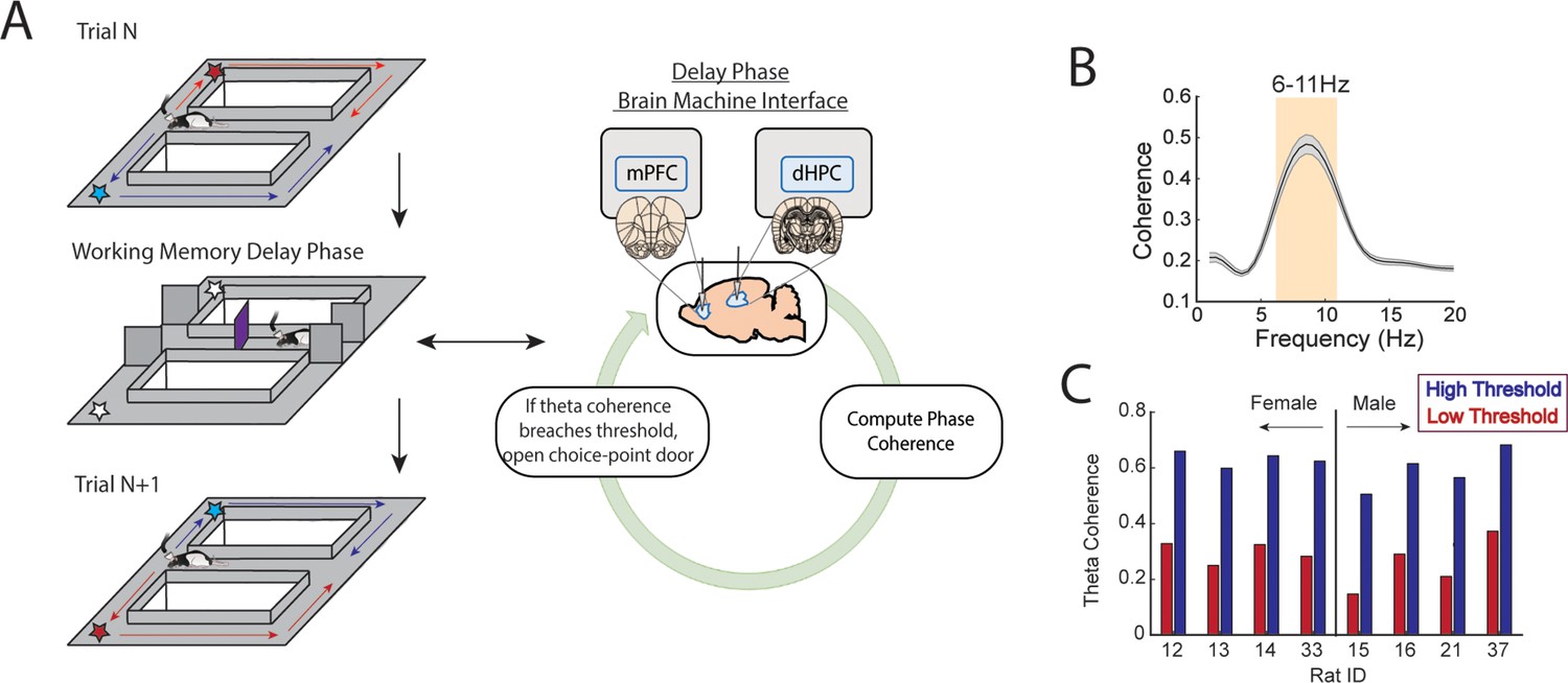
A brain-machine interface that harnesses endogenous medial prefrontal cortex (mPFC)-hippocampal theta coherence on a working memory task.
(A) Schematic of brain-machine interfacing as rats performed a delayed alternation task on an automated T-maze. The delayed alternation task requires rats to alternate between left and right reward zones. Blue arrows and stars denote correct (rewarded) trajectories while red arrows and stars represent incorrect (unrewarded) trajectories. The rat was confined to the delay zone with three barriers. On a subset of trials, we computed mPFC-hippocampal theta coherence in real time during the delay and trials were initiated contingent upon theta coherence magnitude. (B) Frequency by coherence distribution calculated on data collected in real time. For brain-machine interfacing experiments, theta coherence was defined as the averaged coherence values between 6 and 11 Hz. Data are represented as the mean ± s.e.m. (C) Thresholds for high and low magnitude coherence were estimated based on distributions of theta coherence values that were unique to individual rats (see Figure 1—figure supplement 2I and J and Methods). N=8 rats (4 female, 4 male).
Figure 1—figure supplement 1
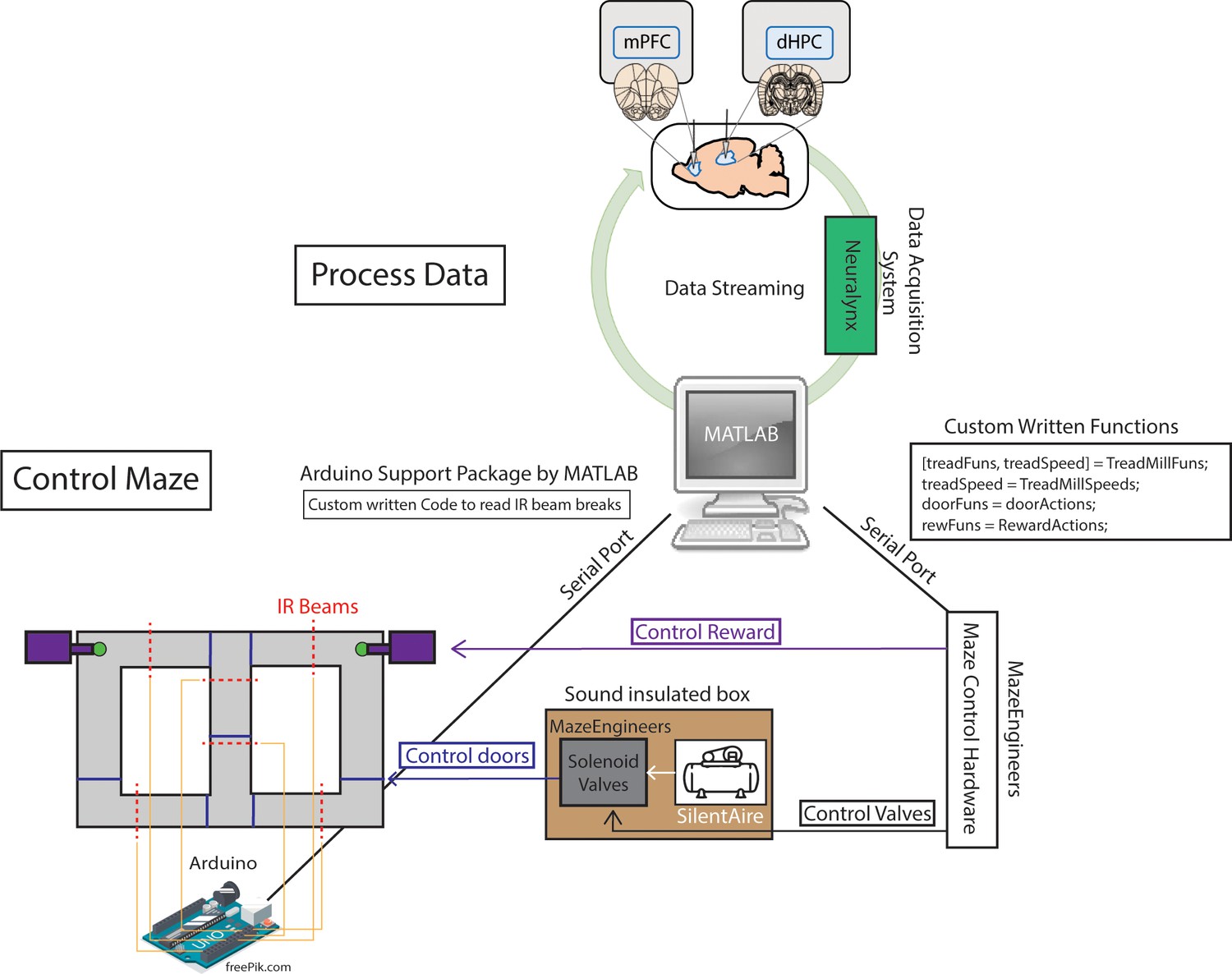
Two independent loops support brain-machine interfacing.
Schematic demonstration of how neural data could be processed in between control of the automatic T-maze. In terms of maze control, serial ports were formed between hardware built from MazeEngineers and an Arduino Uno board. Custom written functions were used to control solenoid valves, which pushed or released air, mediated by a silent air compressor. The solenoid valves and air compressor were placed in a large wooden box, with foam insulation walls, in order to reduce noise. The MazeEngineers hardware was also programmed to control the release of chocolate pellets for reward delivery. Using Arduino-powered infrared beam breaks (yellow lines denote connections), MATLAB could detect the exact location of the rat in order to carry out the programmed sequence of the task. For example, as rats approached a reward zone, an infrared beam break triggered the closing of a door (blue lines on maze) and the release of a reward (if a choice was correct).
Figure 1—figure supplement 2
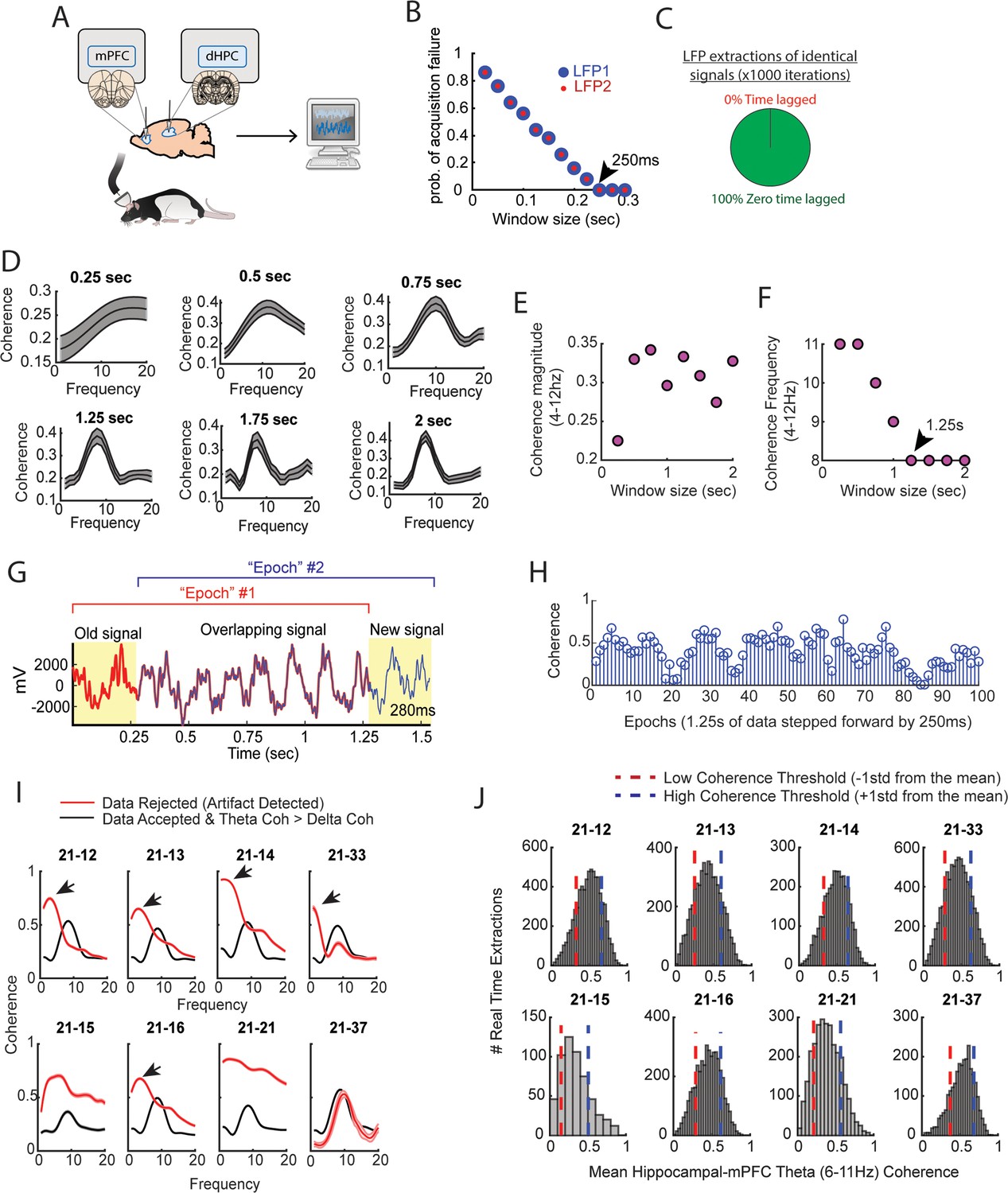
Brain-machine interface parameterization.
(A) Cartoon schematic showing that signals were collected from the medial prefrontal cortex (mPFC) and hippocampus, then sent to a computer for processing in real time. (B) Two local field potential (LFP) signals were collected in real time at various intervals, with an interval being defined as the time lag in between attempted streaming from the acquisition system recording the neural data and the computer processing the data. Each data point represents an average from 50 attempted streaming events. Notice the negative relationship between the probability of streaming failure and the amount of data streamed. If our program waited 250 ms in between streaming attempts, we found a 0 probability of acquisition failure. In practice, even at this interval, there were still rare acquisition failures that could be accounted for via programming. (C) Two identical signals were programmed as two different recording channels in the DigitalLynx SX data acquisition system to test if serial streaming of two signals induced time lags (e.g. one signal being temporally shifted in time relative to the other signal). We found that all serial streaming events were identical, indicating a zero time lag in between extracting two signals in real time. (D) Visual representation of the analyses shown in (E and F). Notice that the shape of the coherence distributions varies as a function of the amount of data analyzed, but is generally consistent when analyzing at least 1.25 s worth of data. (E) Averaged coherence magnitude (4–12 Hz) as a function of data size. Notice that at 250 ms, coherence magnitude was highly underestimated. (F) Coherence frequency (the frequency corresponding to the strongest coherence values) was modulated by the amount of data analyzed. Notice the coherence frequency to taper at 8 Hz when analyzing at least 1.25 s worth of data. (G) A coherence ‘epoch’ was defined as a 1.25 s window, with each epoch varying by 250 ms in time. The red colored signal was acquired first, the blue colored signal was acquired after 250 ms, and the two signals were overlaid for visualization purposes. (H) Stem plot showing theta coherence epochs as a function of time. Notice the rather smooth transitions between stronger and weaker theta coherence values, consistent with a moving window approach sharing a large proportion of data (G). (I) Real-time artifact rejection procedures contained strong delta coherence across all rats (red curves). When these artifact rejection procedures were combined with rejection of signals if delta coherence was stronger than theta coherence, highly consistent coherence distributions emerged (black curves). (J) By performing these methods in real time and gathering hundreds-to-thousands of theta coherence values (6–11 Hz), coherence distributions were generated via offline data analysis. ‘High’ and ‘low’ magnitude theta coherence thresholds were then defined as +1 std and –1 std from the mean theta coherence value, respectively.
Figure 1—figure supplement 3
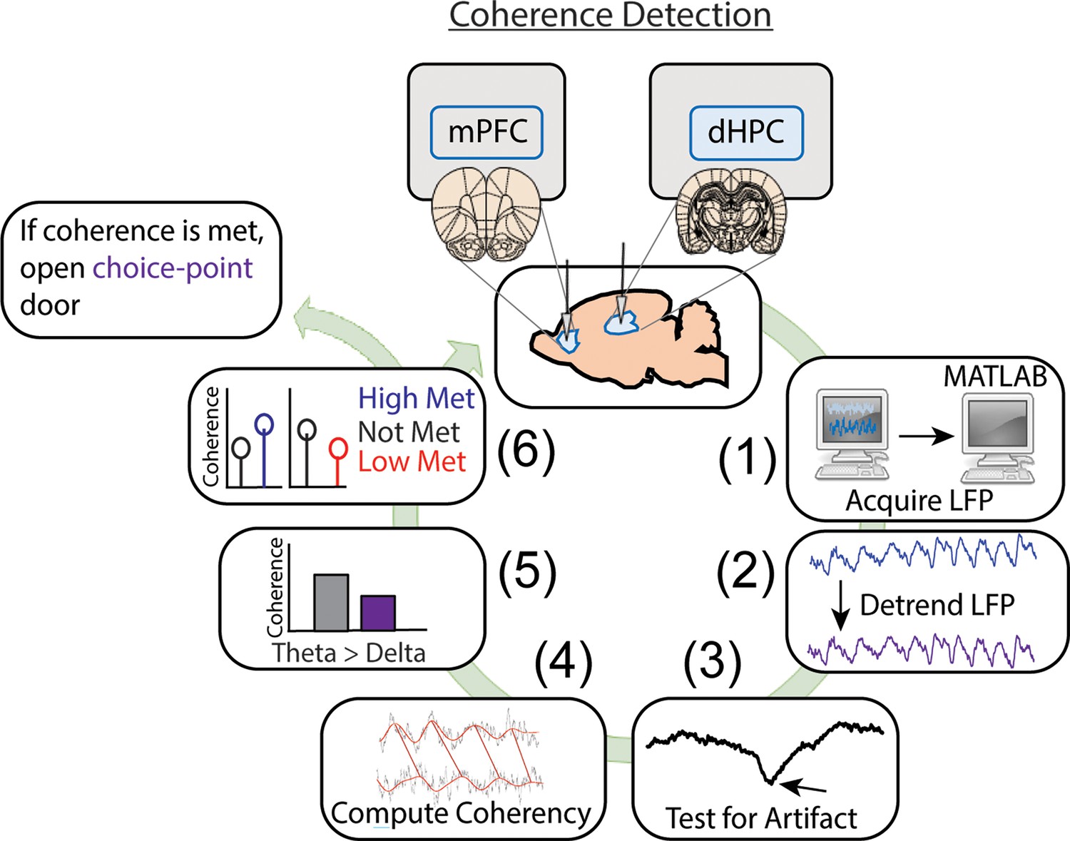
Detailed representation of brain-machine interfacing.
Data were acquired in real time, then processed in MATLAB. Data processing consisted of fitting and removing a third-degree polynomial to detrend the signals (1.25 s worth of data), then signals were tested for artifacts. These artifacts were defined as large voltage fluctuations exceeding 4 std of a mean and standard deviation generated from 10 min baseline recordings (as rats occupied a flower pot with motion being more restricted than when on the maze). In real time, if voltage fluctuations exceeded 4 std and these events saturated >1% of the signal, then the brain-machine interfacing restarted. If no artifacts were detected, coherence was calculated in 0.5 Hz steps from 1 to 20 Hz using mscohere and only if delta coherence (1–4 Hz) exceeded theta coherence (6–11 Hz), then brain-machine interfacing restarted. If on a high coherence trial, theta coherence exceeded delta coherence, and theta coherence was higher than the predetermined threshold, a door was opened, releasing the rat from being sequestered in the delay zone that separated trials. Upon release, rats could make a choice. Similarly, on low coherence trials, if the criterion described above was met and theta coherence was lower than the predetermined threshold, then the trial was initiated. If coherence was not met, the brain-machine interface restarted.
Figure 1—figure supplement 4
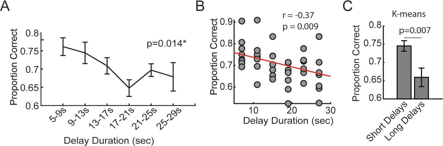
The effect of delay duration on delayed alternation task performance.
(A) During task training, time spent in the delay zone was binned and the average proportion correct (# correct trials/# trials) was calculated. There was a significant effect of delay duration on future choice outcomes (F(5,35) = 3.38; repeated measures ANOVA; N=8 rats, 4 male, 4 female). (B) Same data from (A), but represented as a scatter plot for correlation analysis. (C) K-means clustering was used to algorithmically define short and long delay durations. Short delays were defined as the minimum possible delay length (5 s) to the minimum centroid (10.34 s). Long delays were defined as the maximum centroid (23.58 s) to the maximum possible delay length (30 s). There was a greater proportion of correct choices following short delays relative to long delays (t(7) = 3.7, p=0.007, ci = [3.15, 14.1]). These analyses validate the delayed alternation task as a working memory-dependent task. *p<0.05. Data are represented as the mean ± s.e.m.
Figure 2 with 2 supplements
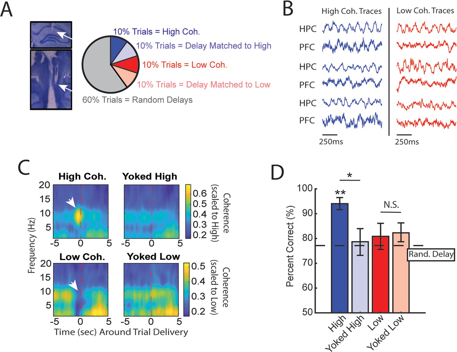
High medial prefrontal cortex (mPFC)-hippocampal theta coherence can be used to enhance performance of a working memory-dependent task.
(A) Left panel: Histology from a representative rat showing electrode tracks in the dorsal hippocampus (top) and mPFC (bottom). Right panel: Distribution of trial types within a session. Within 10-trial blocks, 20% of trials were initiated based on high or low mPFC-hippocampal theta coherence, 20% of trials were yoked to the high/low coherence trials, and 60% were triggered following a random delay (5–30 s). Yoked trials were identical in delay duration as high/low coherence trials, but triggered independent of coherence magnitude to control for the negative correlation between delay length and task performance (Figure 1—figure supplement 4). (B) Example local field potential (LFP) traces recorded during high and low coherence trials from three representative rats. The mPFC and hippocampal signals were used to compute theta coherence in real time. (C) Rat-averaged coherograms representing time around trial initiation (x-axis), coherence frequency (y-axis), and coherence magnitude, with warmer colors indicating higher coherence values. White arrows denote strong (top panel) and weak (bottom panel) theta coherence, as expected on trials triggered during high and low coherence states. Notice that on yoked trials, coherence was rather consistent before and after trial initiation, as expected for trials triggered independent of coherence magnitude. (D) Relative to yoked trials, presenting choices to rats when mPFC-hippocampal theta coherence was high led to improved task performance (t(7) = 2.85, pp.c.=0.0248). Trials contingent upon low magnitude theta coherence did not impact task performance compared to delay matched controls (t(7) = –0.26, pp.c.=0.80; paired t-test). Follow-up statistical testing revealed that choice accuracy on high coherence trials was significantly greater than choice accuracy on random delays, consistent with our planned comparisons between high and yoked trials (t(7) = 6.12; p(x4)=0.002). See Supplementary file 1a for statistics. *p<0.05, **p<0.01. Stars (**) above bar graph denotes significance as measured from comparisons relative to random delay choice outcomes (black) and relative to 70% criterion (gray). Subscript ‘p.c.’ indicates planned comparisons. Subscript ‘(x4)’ indicates unplanned comparisons with Bonferroni corrected p-values for the number of unplanned tests performed. N=8 rats (4 male, 4 female).
Figure 2—figure supplement 1
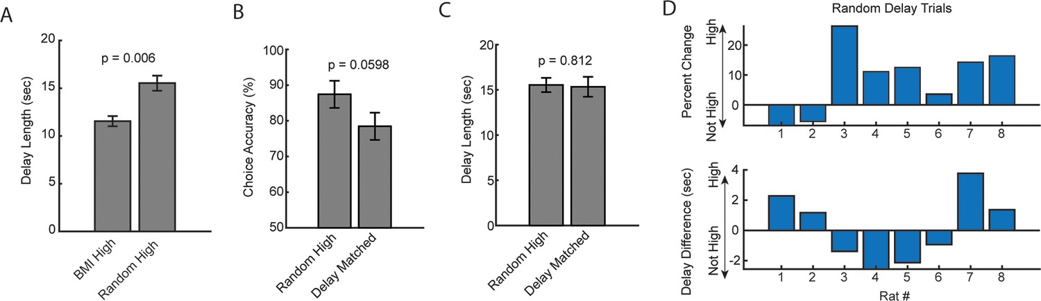
Analysis of random delay trial onset with coincident strong medial prefrontal cortex (mPFC)-hippocampal theta coherence.
(A) Delay duration on brain-machine interfacing trials was significantly shorter when compared to the delay duration on random delay trials with coincident strong mPFC-hippocampal theta coherence (t(7) = –3.8, ci = –6.4 to –1.6, p=0.006; paired t-test). (B) There was not a significant difference between random trials that co-occurred with strong mPFC-hippocampal theta coherence when compared to a distribution of trials with the same delay durations (t(7) = 2.4, ci = [–0.0048 to 0.184], p=0.0598). (C) Estimation of ‘delay matched’ trials in (B) was obtained by finding trials with identical delay durations. Unlike the brain-machine interfacing experiment, these delays were distributed across the session and contribute unequally to the dataset (i.e. a high theta coherence trial in the brain-machine interfacing experiment had exactly one yoked control trial in a 10-trial block). There was no difference in the delay length for random high coherence trials and random trials with identical delay durations (t(7) = 0.25, ci = –1.7 to 2.1, p=0.81). (D) Same data from (A–C) represented across rats. Top panel: Distribution of percent change on the delayed alternation task on random delay trials across rats. Positive values indicate that rats performed better on a random delay trial if it was temporally coincident with strong mPFC-hippocampal theta coherence (‘High’) when compared to estimated delay matched data (‘Not High’). Bottom panel: Difference in delay duration as a function of rat number. Data are represented as the mean ± s.e.m. Statistical test performed was the paired t-test and corresponding p-values are shown above the figure.
Figure 2—figure supplement 2
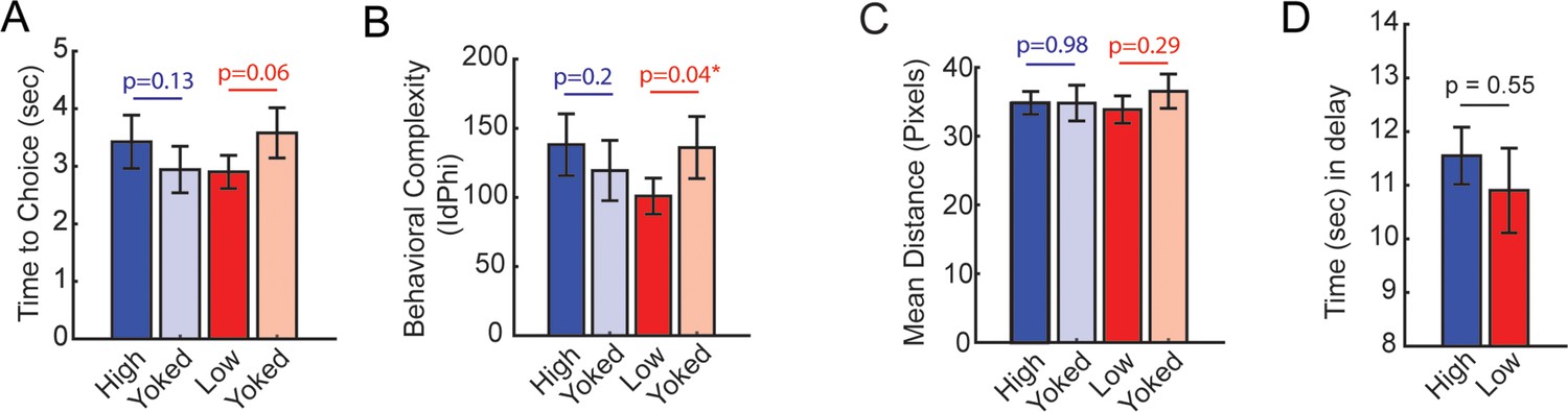
Behavioral analyses from the brain-machine interfacing experiment in Figure 2.
(A) Time to choice was calculated as the amount of time spent from trial initiation to choice exit (infrared beam break that triggers the reward release). There was no statistical difference between high and yoked trials, although there was a trending difference between low and yoked trials (t(7) = –2.23, ci = [–1.4, 0.04]). (B) Behavioral complexity (or head-movement complexity) was measured via the integrative change in absolute angular velocity (IdPhi; Redish, 2016), a common metric to extract vicarious trial and error. Low coherence trials showed significantly lower IdPhi relative to yoked trials (t(7) = –2.5, ci = [–68.36, –1.9]). (C) Distance (in pixels) was calculated in the last 1.25 s before trial initiation, as these times were used to trigger trials according to theta coherence magnitude. There were no differences in distance traveled between coherence and yoked trials. (D) The amount of time spent in the delay zone is a proxy of the amount of time it took to reach theta coherence thresholds. There was no significant difference in delay zone time spent between high and low coherence trials. Planned comparisons between coherence and yoked trials were performed via paired t-tests. *p<0.05. p-Values were shown in figure and the statistics were reported in the figure caption of p<0.05. Data are represented as the mean ± s.e.m.
Figure 3 with 2 supplements
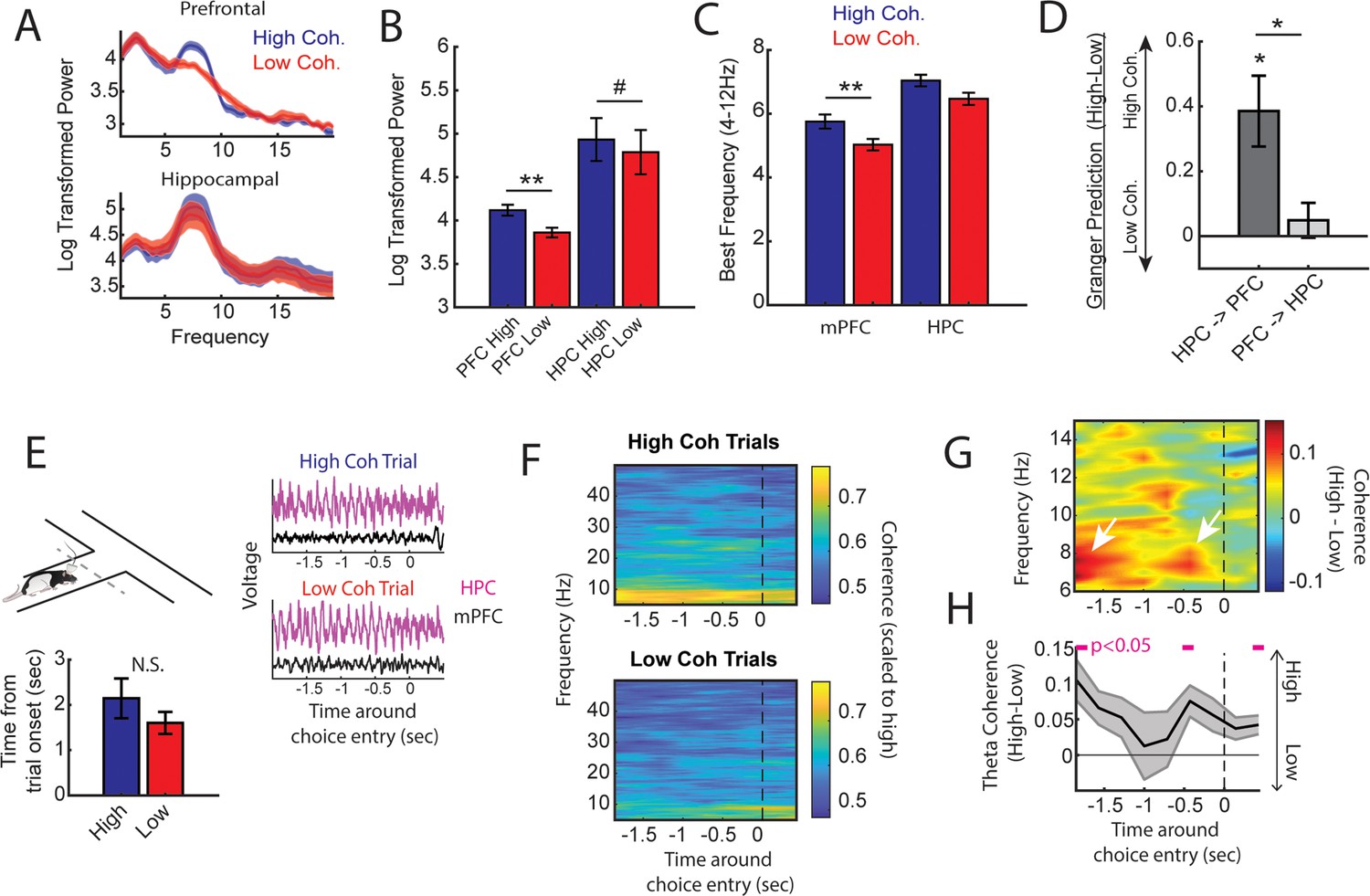
High medial prefrontal cortex (mPFC)-hippocampal theta coherence trials are gated by prefrontal theta rhythms and lead to heightened pre-choice synchrony.
(A) Prefrontal and hippocampal power spectra during the high and low coherence epochs used for brain-machine interfacing (Figures 1 and 2). (B) Prefrontal theta power (6–9 Hz) was significantly greater during high coherence epochs relative to low coherence epochs (t(7) = 5.3, ci = 0.14–0.37, padj(x2)=0.002). Hippocampal theta power was stronger on high coherence compared to low coherence trials (t(7) = 2.47, ci = 0.006–0.28, padj(x2)=0.08, pnot-adj=0.0427). (C) The frequency of prefrontal theta oscillations was significantly higher during high coherence states relative to low coherence states (PFC: t(7) = 3.08, padj(x2)=0.036, ci = 0.16–1.3; hippocampus: t(7) = 1.8, ci = –0.17 to 1.3, p=0.11). Note that 6/8 rats showed higher theta frequency in the hippocampus on high theta coherence states relative to low theta coherence states. Theta frequency was measured by identifying the frequency corresponding to maximum theta power. (D) Hippocampal-to-prefrontal theta directionality was significantly stronger during high theta coherence states relative to low theta coherence states (t(7) = 3.53, ci = [0.12–0.64], padj(x3)=0.029) and was significantly stronger than Granger prediction in the prefrontal-to-hippocampal direction (t(7) = 3.33, ci = 0.097–0.57, padj(x3)=0.038). No significant effect was observed in the prefrontal-hippocampal direction (t(7) = 0.909, p=0.39). (E) Local field potential (LFP) signals (jittered for visualization) were extracted from 2 s before choice point entry (as defined by infrared beam breaks) and 0.5 s afterward. Bar graphs show that the average time to choice entry for high coherence and low coherence trials was between 1.6 and 2.1 s and did not significantly differ between trial types (t(7) = 2.0, p=0.08). (F) Averaged coherograms (N=8 rats) showing coherence as a function of frequency and time surrounding choice point entry. (G) Difference of the coherograms shown in F. White arrows point to initial 6–9 Hz synchronization at –2 s which approximates trial onset (see bar graph in E), and a second time point of heightened theta synchrony before choice entry. (H) Normalized difference scores representing theta coherence as a function of time. Theta coherence at choice entry was significantly stronger on trials triggered by high coherence relative to trials triggered during low coherence (see Supplementary file 1b for raw and corrected p-values). Data are represented as the mean ± s.e.m. across eight rats. *p<0.05, **p<0.01 paired t-tests with Bonferroni p-value corrections when p<0.05. Difference scores were tested against a null of 0. Magenta lines denote p<0.05 after Benjamini-Hochberg corrections.
Figure 3—figure supplement 1
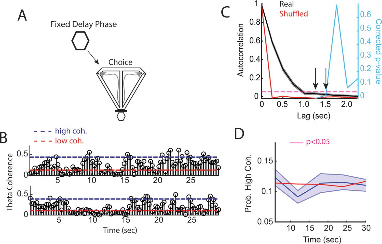
Medial prefrontal cortex (mPFC)-hippocampal theta coherence across a fixed delay.
(A) Task schematic showing that in between delayed alternation choices, rats waited for a fixed and predictable, 30 s delay duration. (B) Two trials showing mPFC-hippocampal theta coherence as a function of time in the delay. Dashed blue line represents high coherence threshold, while the dashed red line denotes low coherence threshold. (C) Sample autocorrelation function of mPFC-hippocampal theta coherence (black line). Data are represented as the mean ± s.e.m. Red line denotes the mean sample autocorrelation function generated by shuffling the distribution of theta coherence values over the delay. Right y-axis shows Bonferroni corrected p-value (five valid comparisons of non-overlapping epochs) of a one-sample t-test against the shuffled autocorrelation mean. Arrows point to significant correlations for non-overlapping lags (coherence epochs were 1.25 s with 250 ms overlap). (D) High mPFC-hippocampal theta coherence events did not increase in frequency toward trial onset (30 s) relative to shuffled theta coherence distributions (red solid line). There was a significant reduction in mPFC-hippocampal theta coherence between 10 and 15 s, as denoted by a magenta bar in the figure (t(21) = 2.9, p=0.046, Bonferroni corrected for five comparisons; one-sample t-test against the shuffled session average).
Figure 3—figure supplement 2
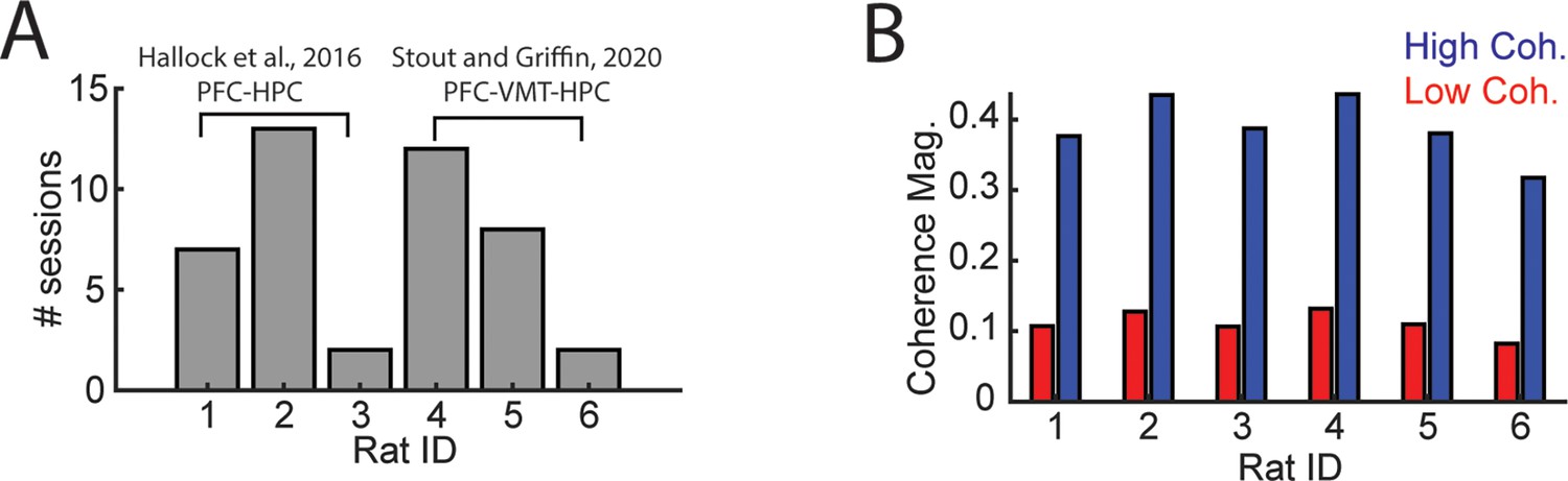
Details regarding mPFC-VMT-HPC recordings.
Data from (A and B) were used for analyses of LFP-LFP synchrony in Figure 5 and Figure 3—figure supplement 1. Data from six rats were analyzed, three from Hallock et al., 2016, with simultaneous mPFC and hippocampal recordings and three from Stout and Griffin, 2020. (B) High and low coherence thresholds were determined for each rat. Notice that thresholds were rather consistent across rats. HPC, hippocampus; LFP, local field potential; mPFC, medial prefrontal cortex; VMT, ventral midline thalamus.
Figure 4
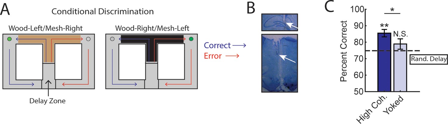
Trials initiated by strong medial prefrontal cortex (mPFC)-hippocampal theta coherence enhance task performance on a two-choice conditional discrimination task.
(A) Schematic of the conditional discrimination task. Wooden or mesh floor inserts were used to guide choice behavior. Rats were randomly assigned to insert-reward contingencies. Like the brain-machine interfacing experiment on the delayed alternation task, trials were initiated when rats were sequestered in the delay zone. (B) Example histology from a representative rat showing electrode placements in the hippocampus and mPFC. (C) Trials initiated during high mPFC-hippocampal theta coherence states led to better task performance when compared to yoked control trials (t(15) = 2.23, ci = 0.29–12.87, p(p.c.)=0.04) or when compared to trials triggered following a random delay (t(15) = 3.8, ci = 4.7–16.6, p(x2)=0.002). There was no difference in choice outcome following yoked and random delay trials (t(15) = 1.0, ci = –4.5 to 12.7, p(x2)=0.33). *p<0.05. **p<0.01. Subscript on p-values shows if comparisons were planned (‘p.c.’) or corrected for multiple comparisons (‘x2’). Data are represented as the mean ± s.e.m. N=16 sessions over three rats.
Figure 5
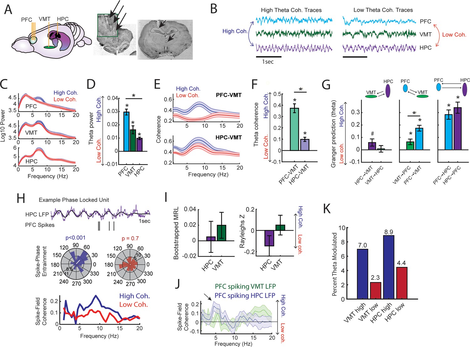
Prefrontal-hippocampal theta synchronization modulates prefrontal-thalamic interactions.
(A) Local field potentials (LFPs) were recorded from the medial prefrontal cortex (mPFC), ventral midline thalamus (VMT), and hippocampal of three rats (N=22 sessions). Right panel shows triple site recordings taken from a representative rat. Green box shows example tetrode tracks from the mPFC. (B) High and low mPFC-hippocampal theta coherence epochs were identified, and LFP from the VMT was extracted. The data shown are collapsed across high or low coherence epochs. (C) Frequency by coherence plots from the mPFC (top panel), VMT (middle panel), and hippocampus (bottom panel). Compare these data to Figure 3. (D) Normalized difference scores comparing theta (6–9 Hz) power between high and low coherence epochs. There was a main effect of brain region on the coherence difference score (F(2,65) = 20.8; p<0.001; one-way ANOVA) with each brain area showing higher theta power during high coherence states relative to low coherence states (PFC: p<0.001; VMT; p<0.001; HPC: p<0.001; see Supplementary file 1c). (E) Theta coherence for mPFC-VMT and VMT-HPC was estimated during high and low mPFC-hippocampal theta coherence states. (F) mPFC-VMT and VMT-HPC theta coherence was stronger during high when compared to low mPFC-hippocampal theta coherence states. mPFC-VMT theta coherence changed more drastically with mPFC-hippocampal theta coherence magnitude (mPFC-VMT: p<0.001; VMT-HPC: p<0.001; mPFC-VMT vs VMT-HPC: p<0.001; see Supplementary file 1d). (G) Multivariate Granger prediction analysis. Left panel shows VMT-HPC theta directionality. Middle panel shows mPFC-VMT theta directionality. Right panel shows mPFC-hippocampal theta directionality. Granger prediction in the mPFC-to-VMT direction was more sensitive to mPFC-hippocampal theta coherence magnitude when compared to Granger prediction in the VMT-to-mPFC direction (statistics in Supplementary file 1e). (H) Top panel shows hippocampal LFP (1 s) and example spikes from an mPFC neuron with significant spike-theta entrainment. Middle panel shows polar plots of the unit in the top panel. Histogram represents the distribution of spike-phase values with the mean result length vector shown as a white bar in the center. Bottom panel shows spike-field coherence for the same neuron. (I) Difference score (high-low/high+low) of bootstrapped MRL and Rayleighs Z-statistic for each neuron as a function of hippocampal or VMT theta. No significant differences were found between high and low mPFC-hippocampal theta coherence states. (J) Spike-field coherence, represented as a difference score. No effects survived p-value correction. Arrow points to a numerical increase to spike-field coherence at hippocampal 4–6 Hz. (K) Percentage of significantly modulated mPFC units to VMT theta and hippocampal theta as a function of strong (blue) or weak (red) mPFC-hippocampal theta coherence states. *p<0.05. Data are represented as the mean ± s.e.m.
Figure 6 with 2 supplements
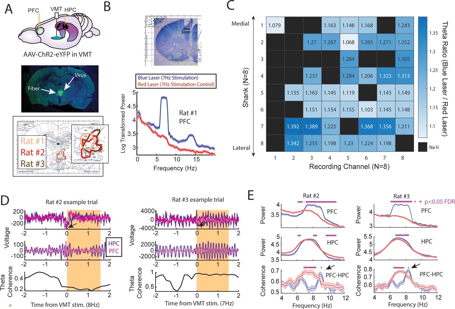
Optogenetic activation of the ventral midline thalamus (VMT) increased prefrontal and hippocampal theta power while dynamically adjusting the medial prefrontal cortex (mPFC)-hippocampal theta coherence distribution.
(A) Top panel, Schematic demonstrating recordings from the mPFC and hippocampus with optogenetic activation of the VMT. Middle panel, example histological confirmation of fiber implant and viral expression targeting the VMT. Bottom panel, Viral expression at similar viral injection coordinates. Notice that all rats showed overlap in viral expression in the nucleus reuniens (brain section overlay from Paxinos and Watson, 2006). (B) Top panel, Histological confirmation of 64ch silicon probe recordings in the dorsal medial prefrontal cortex. Bottom panel, Optogenetic activation of the VMT at 7 Hz produced prefrontal theta rhythms (N=83 blue, 88 red laser events; rat #1). (C) Ratio of log-transformed mPFC theta (6–9 Hz) power between blue and red laser events across silicon probe shanks and channels. Values >1 indicate that theta during blue laser epochs was stronger than during red laser epochs. ‘NaN’ represents an excluded channel. See Figure 6—figure supplement 2 for companion figure. Columns represent recording channels per shank, while rows represent shank number from the corresponding medial-lateral placement in the mPFC (B). (D) Data from rat #2 (N=108 blue, 104 red laser events) and rat #3 (N=113 blue, 101 red laser events). Top panel shows raw local field potential (LFP) traces, middle panel shows theta filtered traces (6–9 Hz), while the bottom panel shows theta coherence as a function of time. Yellow box shows the stimulation event. Arrows point to observed negative deflects in the LFP signals surrounding VMT stimulation onset. (E) Power and coherence analyses performed on data during VMT stimulation (0–1.5 s from laser onset) as a function of frequency (x-axis), brain region (row), and rat (left/right panels). Both mPFC and hippocampal theta power were increased during VMT stimulation. Coherence between mPFC and hippocampal theta rhythms were reduced or enhanced in a frequency-dependent manner during VMT stimulation. Magenta lines denote p<0.05 following Benjamini-Hochberg p-value corrections for two-sample t-tests between the 6 and 11 Hz range. Data are represented as the mean ± s.e.m.
Figure 6—figure supplement 1
Sessions recorded with ventral midline thalamus (VMT) stimulation.
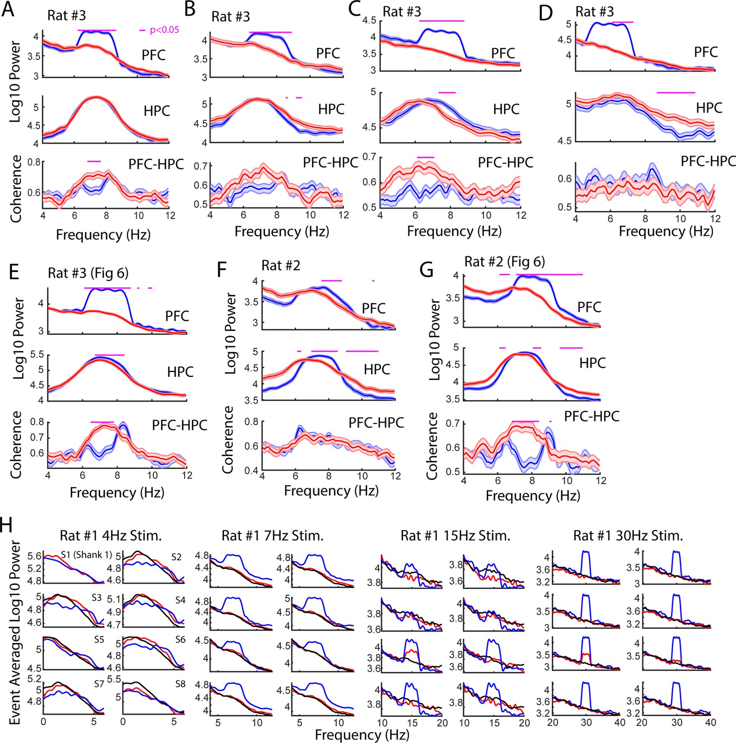
(A) Stimulation of the VMT occurred when hippocampal theta power was greater than hippocampal delta power, when theta coherence was neither above a high coherence threshold nor below a low coherence threshold, and using a phase-lag of –1 phase/pi based on visualization of the phase-lag spectrum (N=57 red, 57 blue laser stimulation events; 1 mW power). (B) Like in (A), laser onset was timed according to a theta delta ratio and theta coherence magnitude, but this occurred as the animal explored a maze (N=91 blue, 78 red laser stimulation events; 1 mW power). (C) Laser onset was timed to epochs when theta power in the hippocampus was less than delta power in the hippocampus (N=114 red, 131 blue laser stimulation events; 1 mW power). (D) The VMT was stimulated at 6 Hz when hippocampal theta power was less than delta power (N=104 red, 93 blue laser events). (E) Same data as shown in Figure 6. VMT stimulation was timed around hippocampal theta power exceeding hippocampal delta power, and mPFC-hippocampal theta coherence magnitude falling in between high and low coherence thresholds (113 blue, 101 red laser events; 4.5 mW power). (F) Rat #2 received 7 Hz stimulation randomly (N=57 red, 57 blue laser stimulation events; 17 mW power). (G) As shown in Figure 6, rat #2 also received a session with 8 Hz VMT stimulation timed to epochs when 8 Hz theta power was the strongest frequency across 1–50 Hz (104 red, 108 blue laser stimulation events). Data are represented as the mean ± s.e.m. Benjamini-Hochberg corrected p-values are represented in magenta, tested over 6–11 Hz with two-sample t-tests. (H) The VMT of rat #3 was stimulated across various frequency ranges to understand the effect of VMT theta on the enhancement of prefrontal oscillation power. Each sub-panel represents a power spectrum calculated over the averaged local field potential (LFP) from 1/8 shanks on a 64ch silicon probe. Blue colors indicate blue laser stimulation, red indicates red laser stimulation, black indicates data after stimulation end. VMT stimulation increased mean power when stimulated at 7 Hz (N=83 blue, 88 red laser events), 15 Hz (N=44 blue, 42 red laser events), and 30 Hz (N=34 blue, 52 red laser events), but altered the shape of the power spectrum at 4 Hz (N=39 blue, 47 red laser events). Red laser stimulation increased mean 15 and 30 Hz power on Shank #5 (S5). Data are represented as the mean.
Figure 6—figure supplement 2
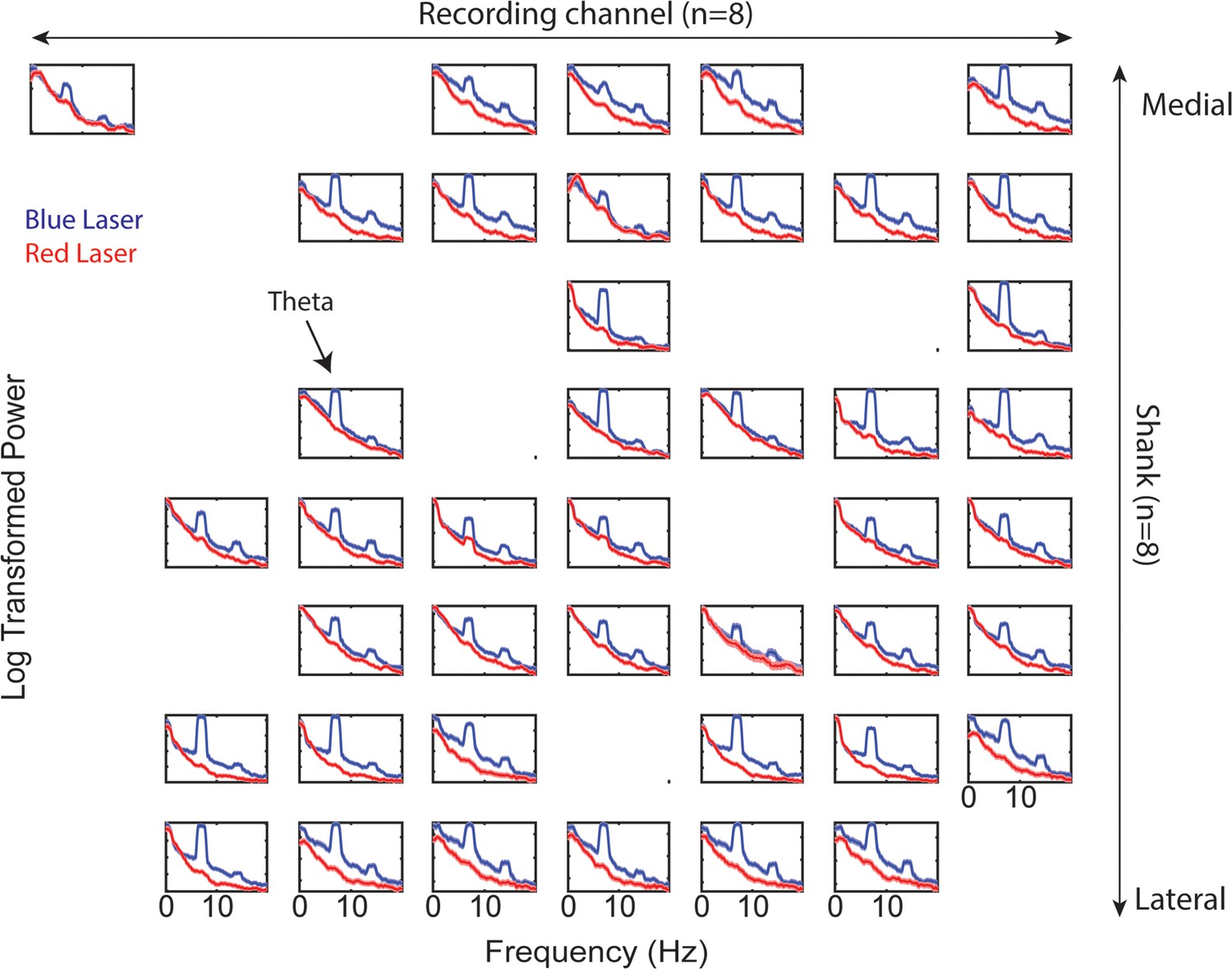
Prefrontal power spectra across recording shanks and channels during ventral midline thalamus stimulation.
Companion figure to Figure 6C. Log-transformed power as a function of frequency. Blue lines represents power spectral density estimates from medial prefrontal cortex (mPFC) signals recorded during ventral midline thalamus stimulation. Red lines represent power spectral density estimates from mPFC signals recorded during control (red laser) stimulation. Figure columns represent recording channels per shank, while rows represent shank number from the corresponding medial-lateral placement in the mPFC (see Figure 6A–C). Data are represented as the mean ± s.e.m.
Author response image 1
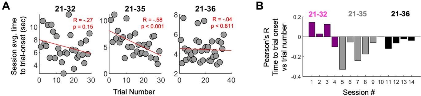
Strong mPFC-hippocampal theta coherence was used to control trial onset for the entirety of forced-navigation sessions.
Time-to-trial onset is a measurement of how long it took for strong coherence to be met. (A) Time-to-trial onset was averaged across sessions for each rat, then plotted as a function of trial number (within-session experience on the forced-runs task). Rat 21-35 showed a significant negative correlation between time-to-trial onset and trial number, indicating that time-to-coherence reduced with experience. The rest of the rats did not display this effect. (B) Correlation between trial-onset and trial number (y-axis); see (A) across sessions (x-axis). A majority of sessions showed a negative correlation between time-to-trial onset and trial number, like what was seen in (A), but the magnitude and sometimes direction of this effect varied considerably even within an animal.
Additional files
-
Supplementary file 1
Tables and statistics.
(a) Statistics from the delayed alternation brain-machine interfacing experiment from Figure 2. (b) Statistics from Figure 3H showing change in medial prefrontal cortex (mPFC)-hippocampal theta coherence difference scores (high coherence – low coherence trials) as rats navigated toward and away from the choice point infrared beam. (c) Statistics from Figure 5 power analysis. (d) Statistics from Figure 5 coherence analysis. (e) Multivariate granger prediction results (Figure 5).
- https://cdn.elifesciences.org/articles/92033/elife-92033-supp1-v1.docx
-
MDAR checklist
- https://cdn.elifesciences.org/articles/92033/elife-92033-mdarchecklist1-v1.docx
Download links
A two-part list of links to download the article, or parts of the article, in various formats.
Downloads (link to download the article as PDF)
Open citations (links to open the citations from this article in various online reference manager services)
Cite this article (links to download the citations from this article in formats compatible with various reference manager tools)
Using synchronized brain rhythms to bias memory-guided decisions
eLife 12:RP92033.
https://doi.org/10.7554/eLife.92033.3


