RNA structures that resist degradation by Xrn1 produce a pathogenic Dengue virus RNA
- Howard Hughes Medical Institute, University of Colorado Denver School of Medicine, United States
- Colorado State University, United States
Figures
Figure 1

sfRNAs are formed by incomplete degradation of the flaviviral genomic RNA by the 5′→3′ exonuclease Xrn1.
(A) Xrn1 (red) likely loads onto decapped, monophosphorylated gRNA and degrades ∼10 kb of RNA before stopping within the viral 3′UTR. The remaining RNA is the sfRNA. (B) In the sfRNAs studied to date, stem-loop (SL) elements near the 5′ border of the 3′UTR/sfRNA appear to be signals for Xrn1 resistance, and are depicted here as cartoon secondary structures. In Dengue and many other FVs, two of these SLs are present in tandem, as shown. The most highly-conserved parts of the RNA are shaded red and putative PK interactions are indicated with dashed lines. Dumbbell elements (not shown) are located 3′ to these SLs.
Figure 2 with 1 supplement
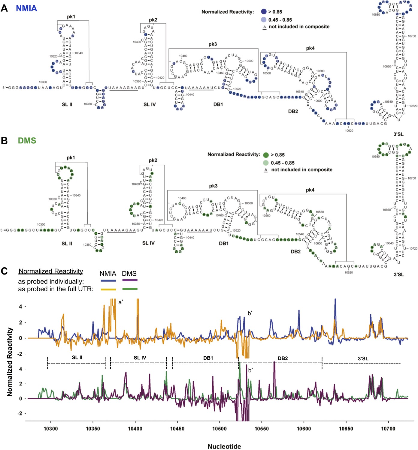
Chemical probing and predicted secondary structure of the DENV2 3′UTR.
(A) The Shapeknots predicted secondary structure of the DENV2 3′UTR with NMIA reactivity data overlaid as indicated (blue). Secondary structure elements are labeled. (B) Same as panel (A), but with DMS reactivity data overlaid (green). (C) Chemical reactivity profiles of the DENV 3′UTR obtained when it is mapped in its entirety or a series of individually transcribed domains. The nucleotide position/number is on the x-axis, the y-axis is normalized reactivity. Locations of secondary structure elements are shown with dashed lines. An ‘ * ‘ indicates a region where the reverse transcriptase tended to stop in the full length 3′UTR. See Supporting Information for additional details.
Figure 2—figure supplement 1
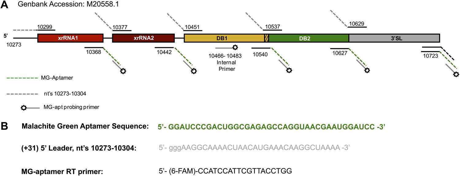
Map of the RNAs used during the chemical probing experiments described in this work.
(A) Schematic of the RNAs mapped in our chemical probing experiments. Numbering indicates the nucleotide positions at the borders of each individually transcribed RNA. Dashed lines indicate the inclusion of the 5′ and 3′ cassettes whose sequences are given in panel (B). The specific sequence of any of these primers is available by request from the authors.
Figure 3 with 1 supplement

Refined secondary structure of SLII RNA in the DENV2 3′UTR.
(A) Chemical probing profiles of (+31)-DVxrRNA1-MG with NMIA (blue) and DMS (green). The y-axis denotes the RNAs sequence/position, the x-axis depicts chemical reactivity. Data represent the average of three independent experiments, error bars are one standard deviation from the mean. Secondary structure elements are indicated to the right of the graphs. (B–D) Overlay of phylogenetic (B), NMIA (C), and DMS (D) data that support the shown refined secondary structure. In panel (B) secondary structure elements are labeled according to standard convention. The RNA shown here was quantitatively resistant to Xrn1 (Figures 5B and 6D,E).
Figure 3—figure supplement 1
Naming Strategy for Xrn1-Resistant RNAs.
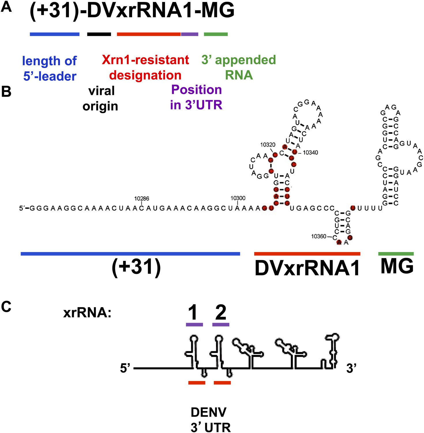
We propose a general nomenclature for discrete RNA structures that resist degradation by Xrn1. We refer to them as ‘Xrn1-resistant RNAs’ (xrRNAs), and we modify this term by including the name of the virus in which the xrRNA is found. When more than one xrRNA is present in a viral RNA, we propose numbering them sequentially. Thus, the 5′ most discrete Xrn1-resistant structure in the Dengue virus genome is named ‘DENV2xrRNA1.’ This nomenclature builds on and is consistent with existing nomenclature and has several advantages: Distinguishes between the discrete RNA structures that resist Xrn1 (xrRNAs) and the larger product of resistance that includes additional sequences of diverse function (sfRNAs). Provides a consistent convention across viral species and independent of idiosyncratic naming of putative secondary structure elements. Is consistent with the accepted practice of classifying and naming RNAs based on function. For example, IRES RNAs are often part of a larger 5′ UTR and may comprise a collection of secondary structural elements, but they are named as discrete functional entities within the 5′ UTR and are identified by their source (e.g., ‘HCV IRES RNA’). The term ‘xrRNA’, modified by source, follows this convention. Allows matching of the name of the xrRNA to the sfRNA it produces. For example, during Kunjin virus infection 4 putative sfRNAs are made (sfRNA1, sfRNA2, etc). With our proposed nomenclature, the name of the xrRNA structure logically corresponds to the product it makes (i.e., sfRNA1 is made by xRNA1, sfRNA2 by xrRNA2 etc). Because this naming convention is based on function and position, this nomenclature is readily extended to xrRNAs that could someday be found in contexts other than flaviviruses. Outline of the naming strategy we propose for Xrn1-Resistant RNAs and application to test RNAs in this study. (A) As shown, we propose a naming strategy that includes designations for an Xrn1-resistant RNA’s function, viral origin, position within in a FV 3′UTR and the presence upstream and downstream RNA sequences. (B) The secondary structure of (+31)-DVxrRNA1-MG illustrates how different components of this naming system apply to the test RNAs used in this study. (C) A stick diagram of the DENV 3′UTR shows how the number scheme we propose for xrRNAs applies to the presence of multiple xrRNAs within a single 3′UTR.
Figure 4
Refined secondary structure of SL IV RNA (DVxrRNA2) in the DENV2 3′UTR.
(A) Chemical probing profiles of (+31)-DVxrRNA2-MG from NMIA (blue) and DMS (green) -probed RNAs. The y-axis contains the sequence and nucleotide numbers, the x-axis depicts chemical reactivity. Data represent the average of three independent experiments, error bars show one standard deviation from the mean. Secondary structure elements are indicated to the right of the graphs. (B–D) Overlay of phylogenetic (B), NMIA (C), and DMS (D) data the support this refined secondary structure. In panel (B) we assign names to the secondary structure elements according to standard convention. The RNA shown here was quantitative resistance to Xrn1 degradation (Figure 6D,E).
Figure 5 with 3 supplements
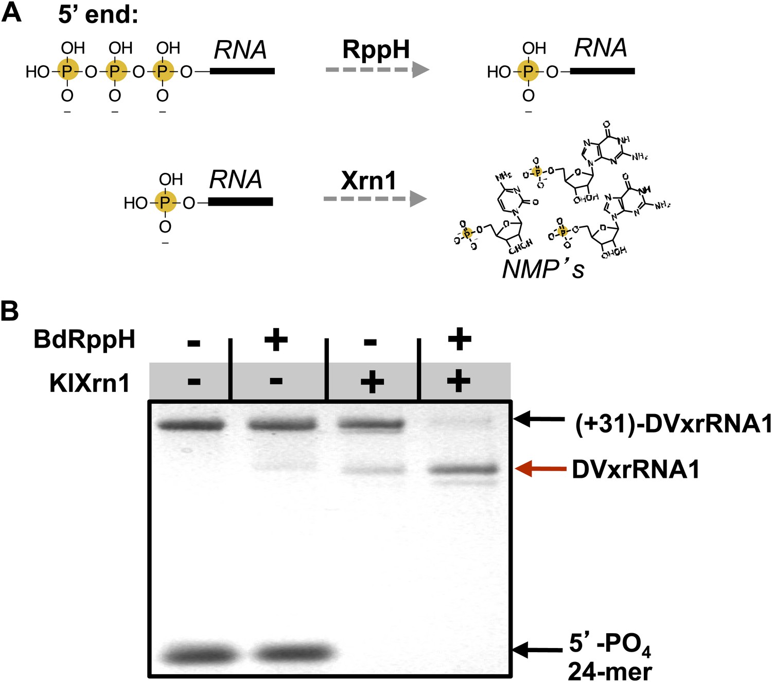
Recapitulation of Xrn1 resistance in vitro.
(A) Reactions carried out by RppH and Xrn1. (B) Gel demonstrating the specificity of each component in the reconstituted reaction and the Xrn1-resistant behavior of (+31)-DVxrRNA1 (the input test RNA), which contains the isolated SL II element after a 31 nucleotide-long leader. The red arrow indicates the truncated product formed by Xrn1 resistance (DVxrRNA1, the resistant RNA). The 24-mer control RNA is labeled.
Figure 5—figure supplement 1
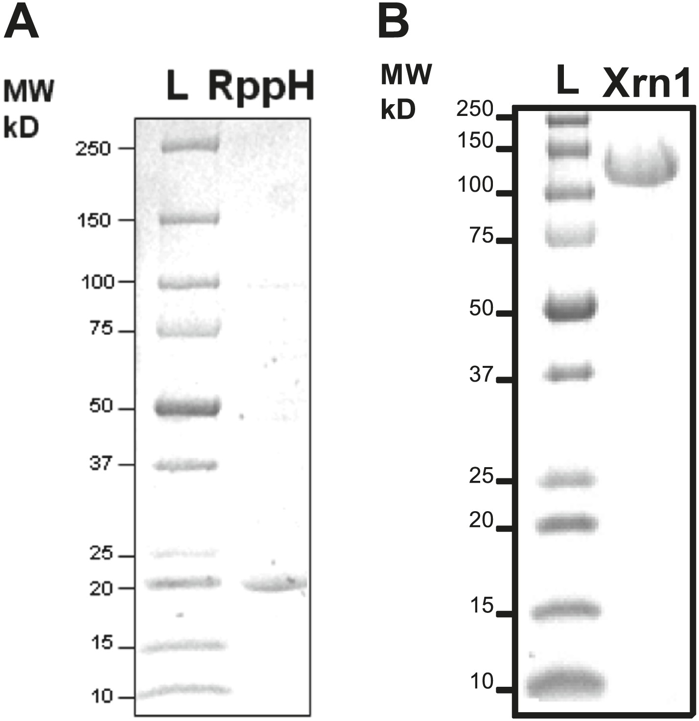
Purification of RNA processing enzymes.
(A) SDS-PAGE gel showing the purity of RNA pyrophosphate hydrolase from Bdelovibrio bacteriovorous (BdRppH, MW = 17 kDa). (B) SDS-PAGE gel showing the purity of Xrn1 from Kluveromyces lactis (KlXrn1, MW = 144 kDa).
Figure 5—figure supplement 2
DVxrRNA1 demonstrates specific resistance to Xrn1.
When reacted with other exonucleases such as the 5′→3′ Phosphodiesterase I from Bovis tarsus (BtPde1) or the 3→5′Phosphodiesterase II from Croatalus adamanteus venom (CaPde2), (+31)-DVxrRNA1 RNA is readily degraded.
Figure 5—figure supplement 3
Examination of in trans protection of other Xrn1 substrates by DVxrRNA1.
(A) Outline of the experiment used to test for inhibition of Xrn1 by DVxrRNA1 constructs. Briefly, increasing amounts of DVxrRNA1 with a 31 nt (+31) or no (+0) added leader were included in reactions of a 24-mer monophophorylated substrate with Xrn1, incubated for 30 min, and resolved by gel electrophoresis. Xrn1-resistant RNAs were added in stoichiometric excess of Xrn1. Conditions are described in ‘Materials and methods’. (B) dPAGE following the reaction described in (A) at 37°C and (C) at 0°C. At the lower temperature, some in trans protection may be observed.
Figure 6

Design of a fluorescence assay for monitoring Xrn1 resistance and testing of individual DENV2 3′UTR structural elements.
(A) Fluorescent properties and structure of the MG dye and MG aptamer. (B) Schematic of the RNA constructs used for monitoring the decay kinetics of individual elements of the DENV 3′UTR. Conserved nucleotides are colored red as in Figure 3B. Green indicates fluorescing MG dye. (C) Cartoon representing the expected outcome when using Xrn1-resistant (top) or non-resistant (bottom) RNAs. Green glow indicates fluorescence. (D) Fluorescence traces of different RNAs over the course of their reaction with Xrn1. X-axis is time and y-axis is relative fluorescence intensity. Data are normalized to (−) Xrn1 controls and are averaged over three independent experiments. Error bars show one standard deviation from the mean. (E) dPAGE analysis of the products of the experiment of panel (D).
Figure 7
Characterization of the products left by Xrn1 resistance.
(A) Gel of RNAs used to map the 5′ end of Xrn1-resistant product RNA. (B) Reverse transcription of RNAs from panel (A). The cartoon inset shows a schematic of the reaction. Dideoxy sequencing lanes are labeled. The location of the stop site (and hence the 5′ border of the product RNA) is shown with a red arrow to the right, along with the sequence of the RNA surrounding this position. (C) Diagram of the experiment used to determine the phosphorylation state of the products left by Xrn1 resistance. Yellow balls indicate non-radioactive phosphates, a green star depicts 32P radioactive phosphates. (D) Gel containing the outcome of the experiment shown in panel (C). Different species of RNA or DNA are labeled to the left and cartooned to the right. Red arrows: Xrn1-resistant product RNA.
Figure 8 with 1 supplement
Mutational analysis of DVxrRNA1.
(A) Secondary structure of DVxrRNA1 with mutations labeled Conserved sequence elements in red. The stop site for Xrn1 is indicated. Inset is a bar graph containing the effects of mutations Xrn1 resistance when quantified using the fluorescence assay. The x-axis identifies each mutant, the y-axis the fraction of MG-tagged RNA degraded at 160 min. C is a non-resistant control RNA. Graph depicts the average of two independent experiments. (B) Gel analysis of the reaction of each mutant with Xrn1 and RppH as in Figure 5.
Figure 8—figure supplement 1
Native PAGE analysis of DVxrRNA1 mutants.
Constructs and conditions are labeled within the figure. A secondary structure depicting the identity of each mutant is displayed in Figure 8 of the main text.
Figure 9
Structural analyses of DVxrRNA1 mutant 6 (mutant in the three-way junction).
(A) Normalized NMIA and DMS reactivity profiles of mutant 6 compared to WT RNA, depicted as in Figures 3 and 4. Colored bars (green and blue) represent the WT RNA and black bars represent mutant 6. The location of the point mutation is shown with a purple shaded box. Reactivity changes are indicated by red boxes. (B) dPAGE of Xrn1 resistance by WT and mutant 6. (C) Non-denaturing (native) PAGE analyses of WT and mutant 6. (D) Secondary structure of the DVxrRNA1 with elements labeled. The purple shaded box shows the location of the mutation. Regions of the structure that show substantial changes in the chemical probing (from panel (A)) are indicated by red boxes.
Figure 10
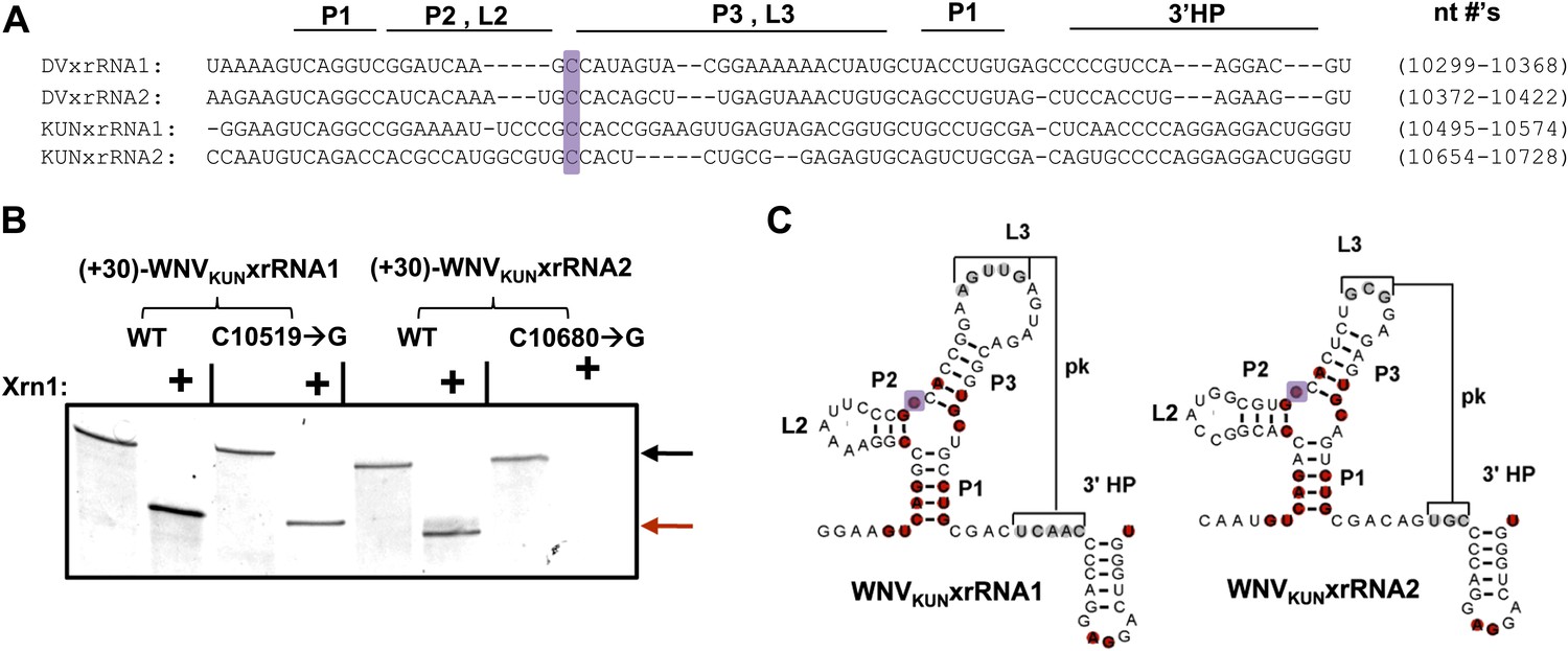
Identification and testing of WNVKUN xrRNA structures.
(A) Sequence alignment of DVxrRNA1, DVxrRNA2, WNVKUNxrRNA1 and WNVKUNxrRNA2. Nucleotide positions are indicated and correspond to Genbank accession numbers M20558.1and AY274504.1 for DENV2 and WNVKUN, respectively. Conserved nucleotides of these RNAs are highlighted in red. The point mutation we made in the three-was junction is indicated with a purple box. (B) dPAGE of the Xrn1 resistance assay run using WNVKUN xrRNAs and C10519→G and C10680→G point mutants. (C) Conserved secondary structure of WNVKUNxrRNA1 and WNVKUNxrRNA2, with conserved nucleotides highlighted and the location of the mutation shaded purple.
Figure 11
sfRNAs produced during infection by wild-type and mutated WNVKUN.
Northern blot analysis of total RNA isolated from human 293T cells infected with WT and mutants WNVKUN, analyzed at 48 h.p.i. The location of molecular weight markers and the identity of sfRNA species are indicated to the left and right of the blot respectively.
Download links
A two-part list of links to download the article, or parts of the article, in various formats.
Downloads (link to download the article as PDF)
Open citations (links to open the citations from this article in various online reference manager services)
Cite this article (links to download the citations from this article in formats compatible with various reference manager tools)
RNA structures that resist degradation by Xrn1 produce a pathogenic Dengue virus RNA
eLife 3:e01892.
https://doi.org/10.7554/eLife.01892


