Geological and taphonomic context for the new hominin species Homo naledi from the Dinaledi Chamber, South Africa
- James Cook University, Australia
- University of the Witwatersrand, South Africa
- University of Johannesburg, South Africa
- University of Wisconsin-Madison, United States
- Simon Fraser University, Canada
- University of Colorado Denver, United States
- Duke University, United States
- Texas A&M University, United States
- University of Zurich, Switzerland
- American University, United States
Figures
Figure 1

Geological setting of Cradle of Humankind and Rising Star cave system.
(A) Geology of Johannesburg Dome and surroundings, showing the Cradle of Humankind world heritage site in bold black outline. (B) surface geology of the immediate surroundings of the Rising Star cave system, showing the fault sets and variable chert content in the dolomite that controlled cave formation. The cave system is confined to a chert-poor stromatolitic dolomite horizon.
Figure 2
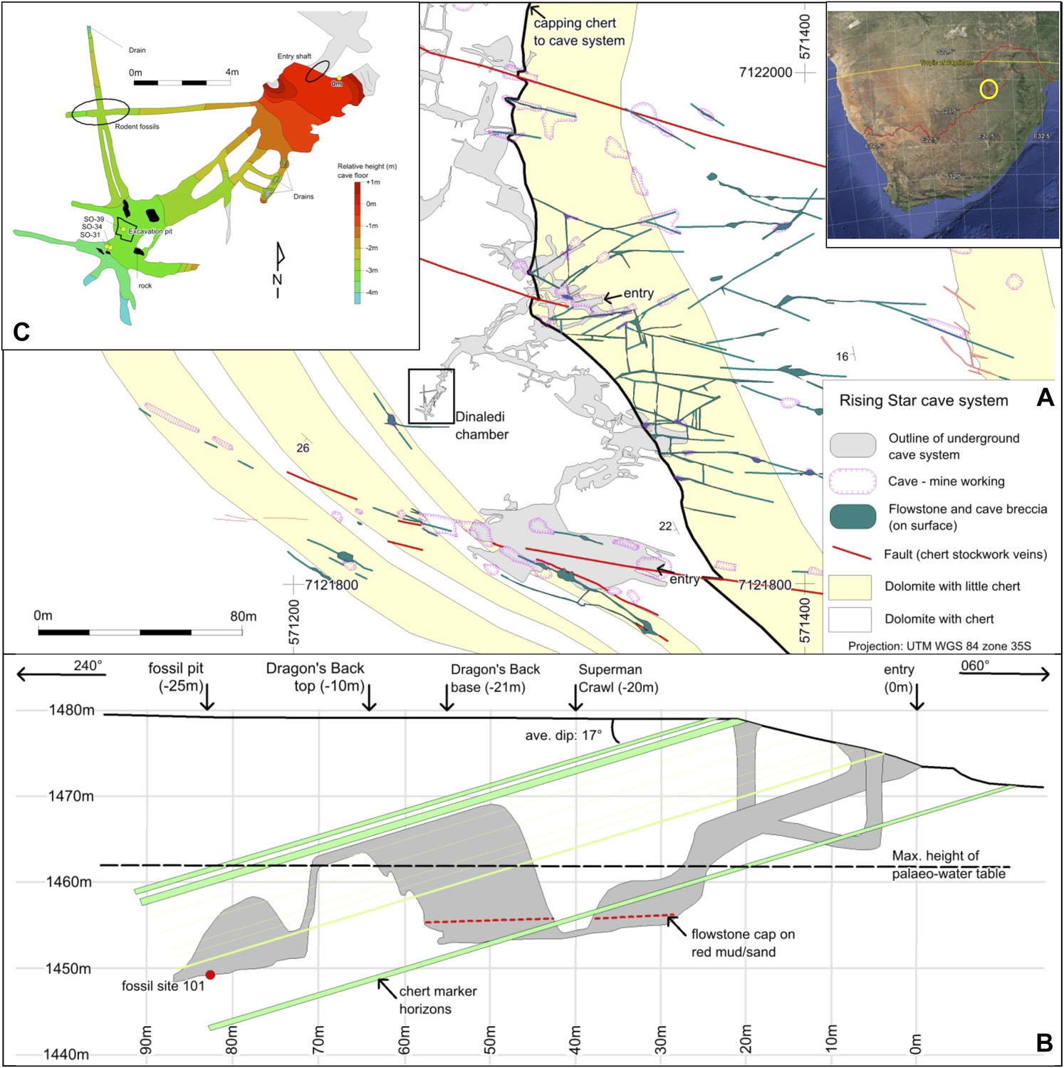
Geological map and cross-section of the Rising Star cave system.
(A) Geological Map showing the distribution of chert-free dolomite and fracture systems controlling the cave. Inset shows the location of the Cradle of Humankind in southern Africa; (B) Northeast-Southwest, schematic cross section through the cave system, relative to several chert marker horizons; (C) Detailed map of the Dinaledi Chamber showing the orientation of the floor and the position of the excavation and sampling sites.
Figure 3
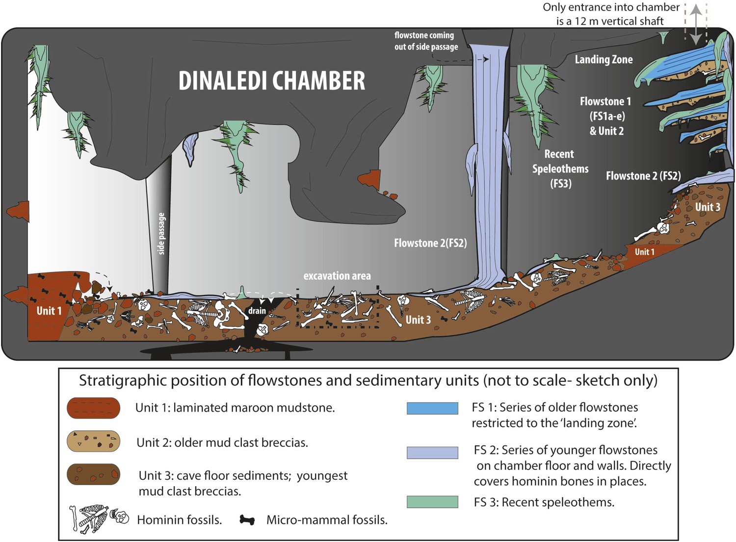
Cartoon illustrating the geological and taphonomic context and distribution of fossils, sediments and flowstones within the Dinaledi Chamber.
The distribution of the different geological units and flowstones is shown together with the inferred distribution of fossil material.
Figure 4
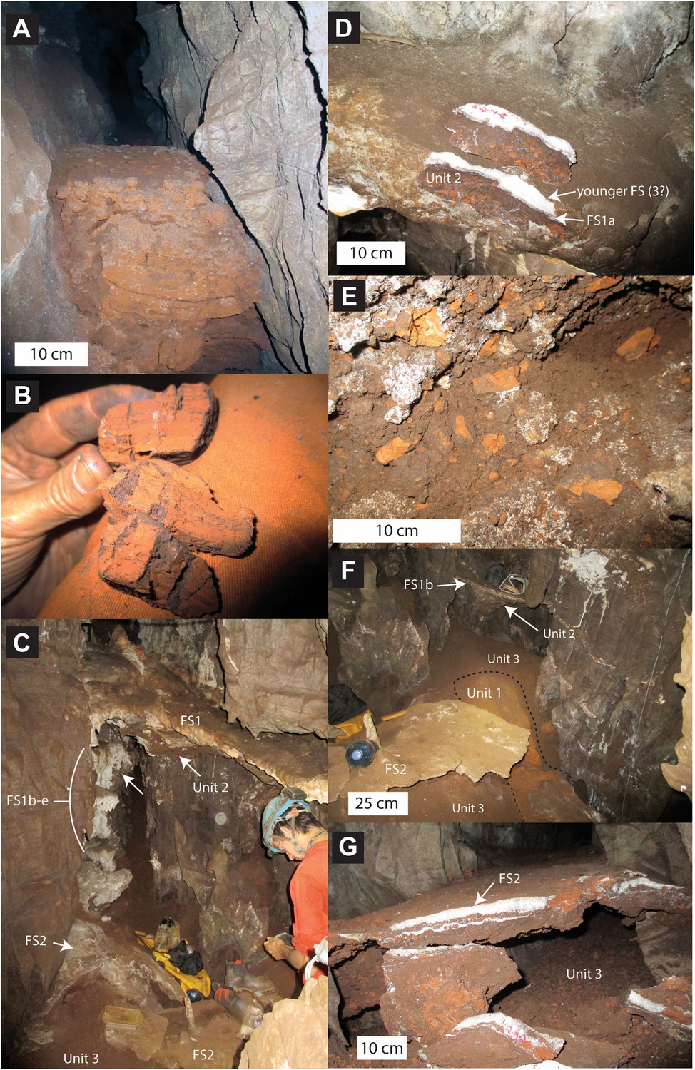
Stratigraphic units and flowstones observed in the Dinaledi Chamber.
(A) Erosional remnant of horizontally laminated Unit 1 strata (Facies 1). (B) Close-up view of Unit 1 (Facies 1a) showing fine laminations and small invertebrate burrows (note fine sand infilling in burrows). (C) Overview photo of the Dinaledi Chamber, directly to the east of the entrance point into the chamber. Photo shows distribution of Flowstones 1–3 and stratigraphic Units 2 and 3. (D) Close-up view of Flowstone 1 encasing sediment of Unit 2. Note that several generations of flowstone (Flowstones 1a–e) are coating Unit 2. The thin, clear lower layer is Flowstone 1a, and the overlying white flowstone is either Flowstone 2 or 3. (E) Close-up view of Unit 2, consisting of generally poorly-cemented Facies 2 sediment. (F) View of the chamber floor near the entry point. On the cave floor, a large erosional remnant of Unit 1 (orange laminated mudstone of Facies 1a), is surrounded by mud-clast breccia of Unit 3 (main hominin bearing unit). Note that Flowstone 2 has been undercut by post-depositional erosion of Unit 3, which, in this location has resulted in a lowering of the floor by as much as 25 cm. (G) Flowstone 2 overlying Unit 3 in one of the chamber's side passages. In this location Unit 3 has also been partly eroded after depositional from underneath the flowstone drape, leaving a hanging remnant, with some indurated sediment of Unit 3 attached to its base. Note the continued deposition of sediment above Flowstone 2.
Figure 5
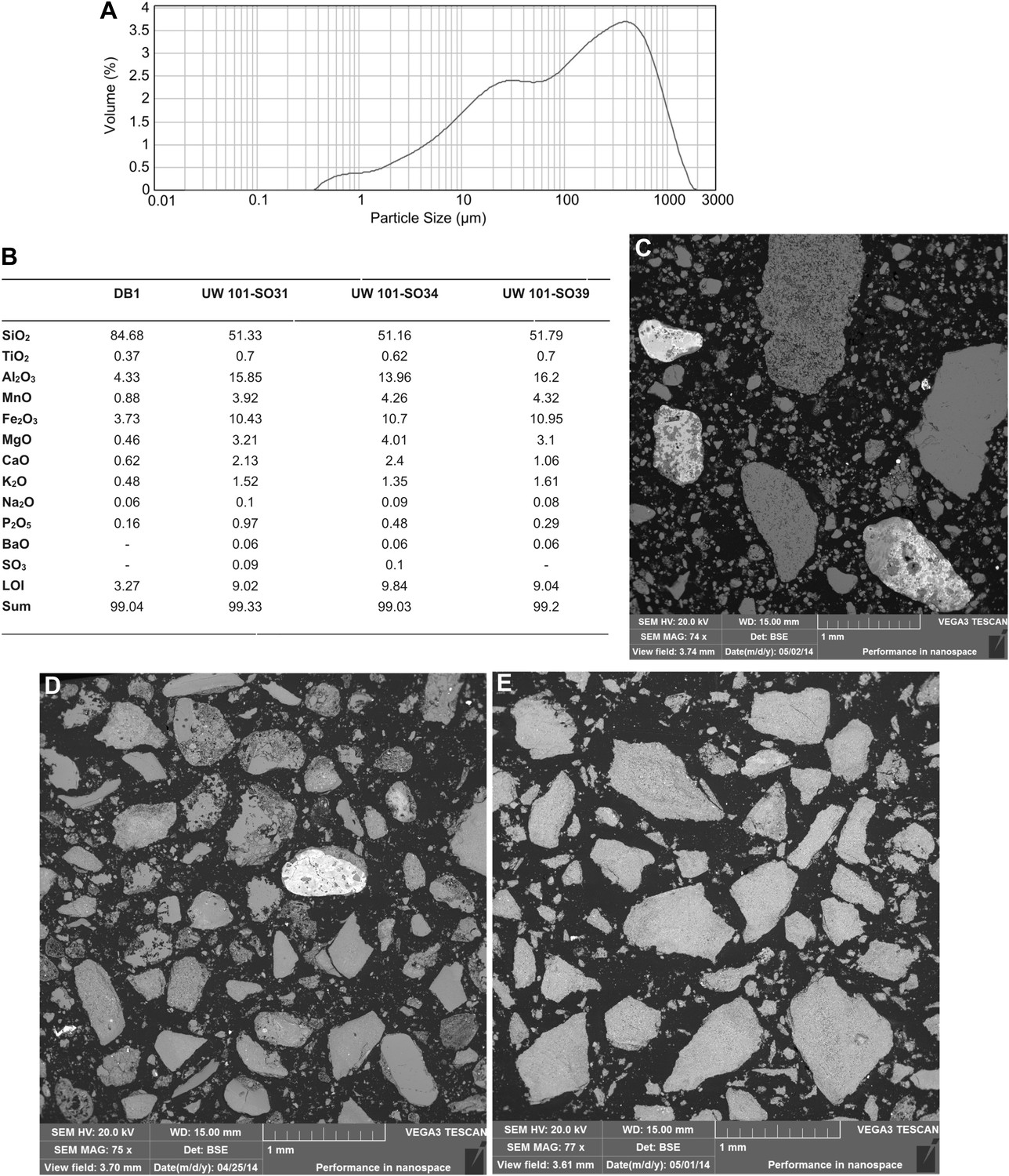
Data and characteristics of cave floor sediments (Facies 2) from the Dinaledi and Dragon's Back Chambers.
(A) Grain size distribution of sample UW101-SO-39 (Figure 2C). The bulk of the sample material falls within a size fraction corresponding to silt and fine-grained sand. Some coarser mudstone fragments did not disintegrate when immersed in water, likely due to considerable Mn- and Fe-oxide micro-concretionary development in the orange mudstone. Because some mudstone fragments are well lithified the particle size distribution is skewed towards the coarser grain-size values. (B) Results of XRF analyses of bulk samples of three floor sediments from the Dinaledi Chamber (UW101-SO31, -34 and -39) and one from the Dragon's Back chamber (DB-1). The sample from the Dragon's Back Chamber has a radically different composition from those of the Dinaledi Chamber, with the high SiO2 content reflecting its dominance of quartz. The Dinaledi samples have much higher Al2O3 and K2O contents than DB-1, indicating a higher content of clay minerals and mica, and higher CaO, MgO, MnO, and total Fe oxide contents which reflect alterations and inclusions. The higher P2O5 content of the Dinaledi samples is probably located in comminuted bone fragments which are seen macroscopically. The volatiles content (LOI) of the Dinaledi samples is also higher than in DB-1, in accord with a higher total clay mineral and mica content. (C–E) Backscattered electron (BSE) wide-field images of grain mounts from floor sediments. Brighter shades indicate the presence of heavier elements, mainly Mn and Fe in altered grains. (C) DB-1, Dragon's Back Chamber, large fragments are quartz and chert, partly altered. (D) UW101-SO34. (E) UW101-SO39. In these samples the large fragments are almost exclusively clay; note their angular shape which shows these to be locally derived.
Figure 6
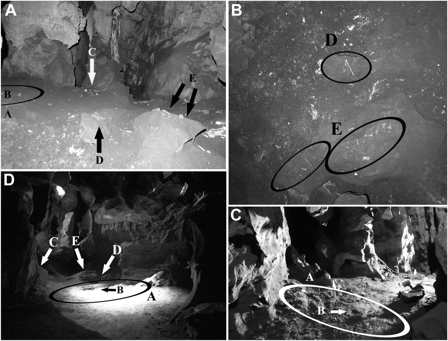
Views of the Dinaledi Chamber.
Clockwise from top left: (A) Photograph taken during initial exploration of the chamber; view to the N. Ellipse ‘A’ indicates the area where most of the hominid material was excavated. Letter ‘B’ shows the location of the cranial fragment that was one of the first pieces removed from the chamber. Arrows ‘C, D and E’ indicate areas of concentrated surface material. Block E is ∼ 50 cm across. (B) pre-excavation view of the chamber floor. ‘D’ and ‘E’ included hominid teeth, (intrusive) bird bones and several long bone fragments that had been ‘arranged’ on rocks by an unknown caver prior to discovery by our caving team. Top of the photograph point to the NE. Base of the photograph is 80 cm. (C) view of the primary excavation area prior to excavation looking in a NE direction. The diameter of the ellipse is 1 m for scale (D) the excavation area at the end of the first round of excavations looking in a SSE direction (November 2013). Ellipse A is the same as in previous figures. Arrow B shows the fragment of a long bone that was uncovered after the cranial fragment had been removed. Arrows C, D and E indicate where surface concentrations had previously been. The diameter of the ellipse is 1 m for scale.
Figure 7
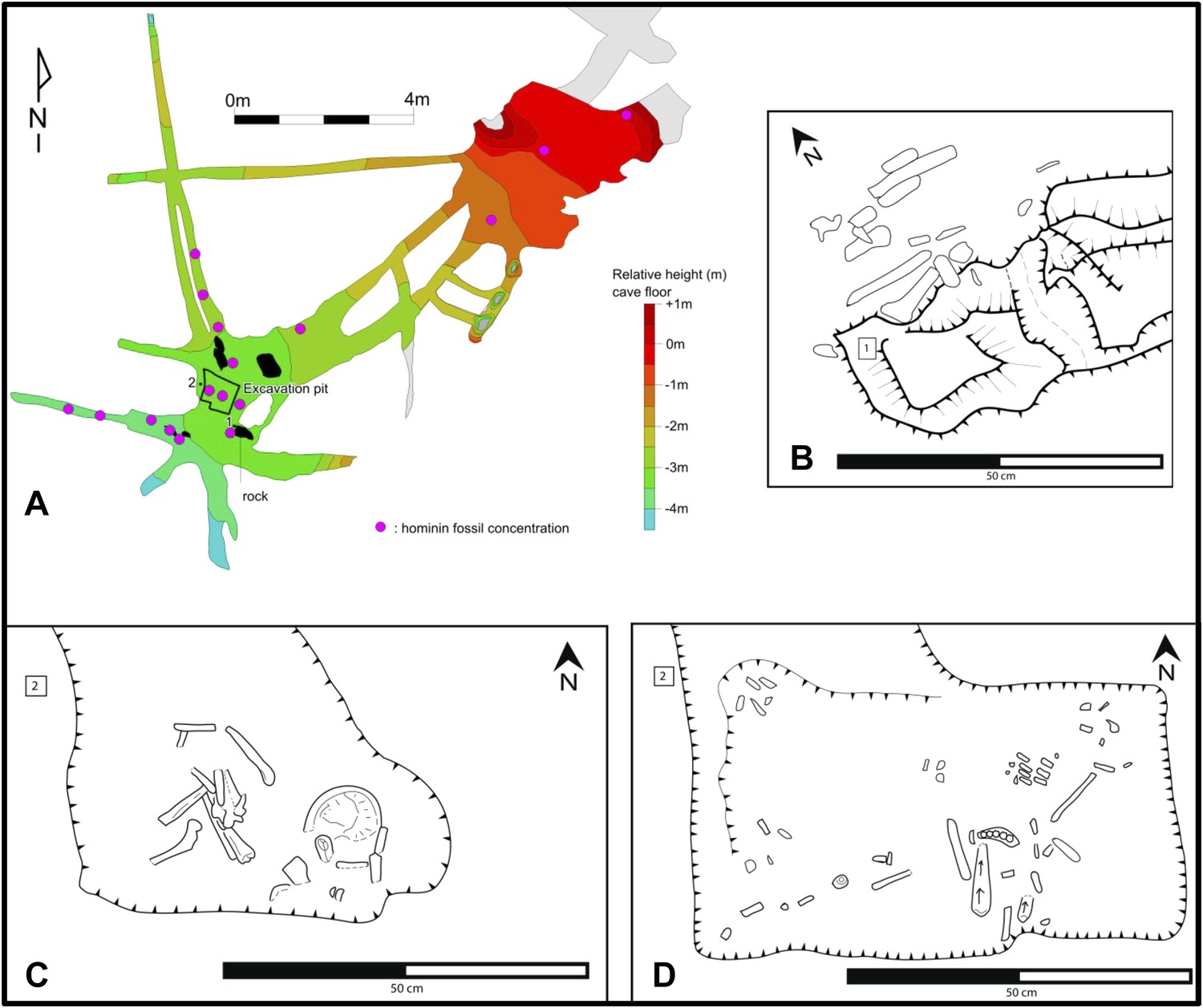
Map of the cave chamber showing the distribution of hominin fossils.
(A) distribution of concentrations of bone fragments of H. naledi along the floor of the Dinaledi Chamber. The positions of maps (B) and (C), (D) are shown relative to survey pegs 1 and 2 respectively. (B) Concentration of long bone fragments encountered next to a rock embedded in Unit 3 sediment. (C) Distribution of fossils in the excavation pit at the start of the excavations in November 2013 (∼5 cm below surface). (D) Distribution of fossils in the excavation pit during excavations in March 2014 (∼15 cm below surface); the long-bone in the central part of the pit is in a near-vertical position and is shown in Figure 9C.
Figure 8
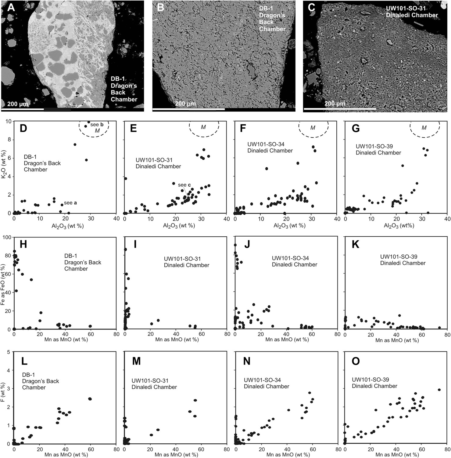
Comparison of selected fragments and electron microprobe analytical data of Facies 2 (Unit 3, floor) sediment in the Dinaledi Chamber, and floor sediments in the Dragon's Back Chamber.
Analytical spot size is 5 μm diameter, which is generally larger than grain sizes. (A) Chert fragment impregnated with Mn oxi-hydroxide from the Dragon's Back Chamber. (B) Shale fragment from the Dragon's Back Chamber. (C) orange mud clast, typical of Facies 2 sediments from the Dinaledi Chamber, note much finer grain size than seen in (B). (D–G) Plots of K2O vs Al2O3 for mud clast fragments in Facies 2 samples from both chambers show an important difference between them. M, muscovite compositional field. The samples from the Dinaledi Chamber (E–G) yield some data close to the muscovite field, probably indicating sericite grains slightly smaller than the spot size, and all show a trend with K/Al ratios much lower than muscovite, up to a high Al2O3 content >30%, which indicates either illite, or mixtures of sericite and kaolinite or other K-free clay minerals. In (E) the analysis of the fragment shown in (C) is indicated. The sample from the Dragon's Back Chamber in (D) shows data in the muscovite field (data point corresponding to [B] is indicated in [D]), but otherwise only low K- and Al-concentrations, which are typical of Mn oxi-hydroxide impregnation (data point corresponding to [a] is indicated in [D]). No analytical data in d correspond to mudstone fragments such as shown in (C). (H–K), plots of Fe as FeO vs Mn as MnO show similarity between the chambers with respect to Fe-Mn oxi-hydroxide impregnations and alterations within the fragments: in both cases, domains with high Fe rarely coincide with domains high in Mn. (L–O), Plots of F vs Mn as MnO. Some elevated F concentrations at zero Mn values occur, but most data show a correlation for samples from both chambers: elevated Mn content is invariably associated with elevated F, with an atomic ratio F/Mn ≈ 0.14. No Mn oxi-hydroxide minerals with F have been described, but partial substitution of F− for OH− as in apatite might be suspected. The similarity of the F/Mn ratios in Mn oxi-hydroxide impregnated fragments from Facies 2 sediments in both chambers suggests a uniform geochemical environment during the Mn oxi-hydroxide alteration event.
Figure 9

Taphonomic spatial patterning within the fossil assemblage exposed in the excavation pit.
Taphonomic signatures and spatial orientations suggest that some of the assemblage may be para-authochthonous in nature, rather than primary or in situ. This scenario provides a mechanism for explaining the combination of near- or fully-anatomically articulated skeletal material and elements, which are heavily commingled and in a non-horizontal resting state (from near-vertical to oblique long-axis orientations). (A) Example of an articulated ankle region. (B) Example of an articulated hand. (C) Example of cluster of skeletal elements showing disarticulated elements in a non-horizontal resting state. Note long bone fragment in near-vertical alignment, compared to normal horizontal or near-horizontal alignment of the commingled elements surrounding it. Labels denote specimen numbers.
Figure 10
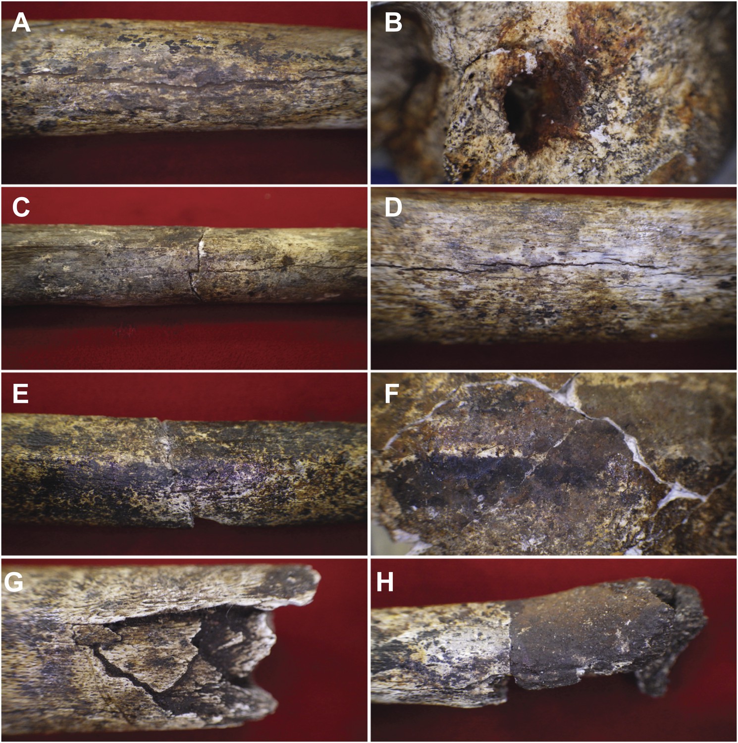
Examples of taphonomic traces recorded on hominin remains.
(A) UW101–1288 tibial diaphysis showing evidence of mineral staining adhering to the cortex. The fossil shows evidence of dark zone sub-aerial or sub-surface weathering. Specimen shows a central midline crack with sediment infill, which separates conjoined manganese concretions. (B) UW101–419 (Cranium A[1]) showing iron oxide staining around the external auditory meatus. (C) UW101–312 and 1040 conjoined fragments of a tibial shaft, showing stepped transverse fracture (post-mortem) of the mid-shaft; note longitudinal crack, and evidence of invertebrate modification. (D) UW101–1288 tibial diaphysis showing a weathering pattern typical of Stage 1 evidenced by fine longitudinal cracks, without concomitant flaking, delamination, or the formation of fibrous texture. (E) UW101–1074 tibial shaft showing manganese mineral concretions overlying yellow staining across the diaphysis. (F) Specimen UW 101–419 Cranium A(1) displaying tide lines of dark brown, reddish brown and yellow staining, which extends across different vault fragment. (G) UW101–498 tibial shaft, showing comminuted post-mortem fracture/crushing preserved by sediment infiltrate. (H) UW101–1070 segment of tibial diaphysis displaying differential mineral staining patterns between conjoined fragments.
Figure 11
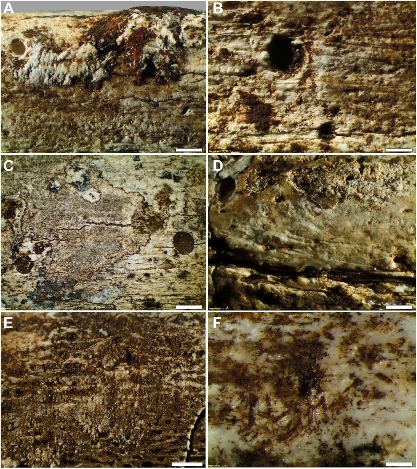
Taphonomy—surface modifications.
(A) Removal of the bone surface with sets of shallow, evenly spaced, multiple parallel striations on fibula (UW101–1037), which run longitudinal with the main axis of the bone and are interpreted as gastropod radula damage. (B) Fibula (UW101–1037) showing removal of the bone surface with sets of shallow, evenly spaced, multiple parallel striations that follow the collagen fibres together with shallow circular pits ranging from 0.1 to 3 mm in diameter, the bases of which may be smooth, cupped, or covered with multiple parallel striations. These features have been attributed to gastropod radula damage. (C) Tibia (UW101–484) showing removal of the bone surface with sets of shallow, striations that show a smooth scalloped edge together with circular pits ranging from 0.1 to 3 mm in diameter interpreted as the result of gnawing by beetle larvae. (D) Tibia (UW101–484) with areas of surface removal that have a straight edge associated with scrape marks interpreted as damage made by a beetle mandible. (E) Fibula (UW101–1037) with sets of shallow, evenly spaced, multiple parallel striations orientated transverse to the long axis of the bone interpreted as gastropod radula damage, resulting in an etched surface appearance that exposes underlying structures. (F) Tibia (UW101–484) showing clusters of large individual striations that are variably arrow-shaped and often overlap, interpreted as damage made by a beetle mandible. Compare with Figure 12 which shows surface modifications made by modern snails and beetles and their larvae. The scale bar in all samples equals 1 mm.
Figure 12
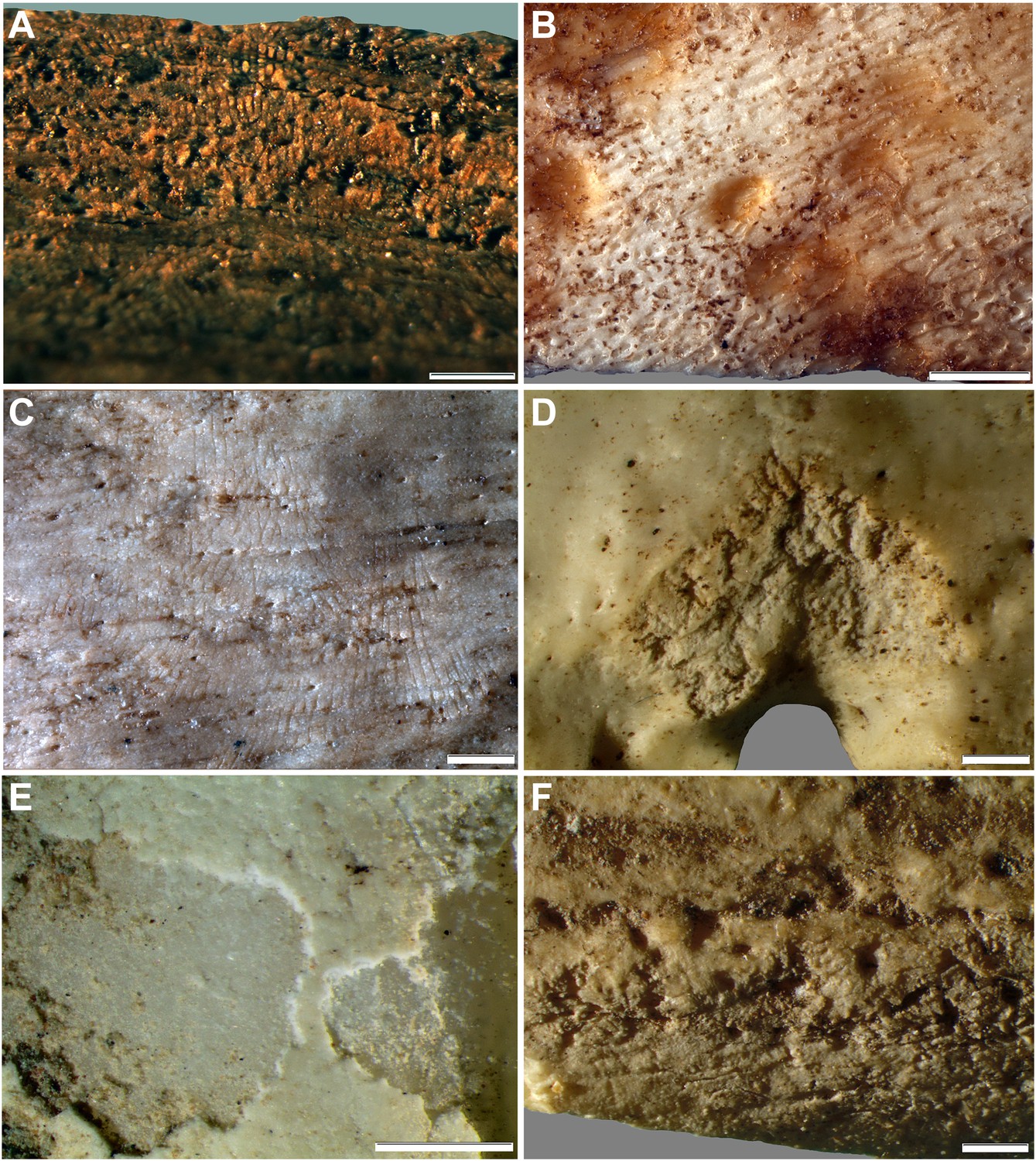
Comparative examples of surface modifications on bone made by modern snails and beetles and their larvae after four months in controlled experiments.
Gastropods and beetles were found to produce similar modifications to those observed on the Rising Star hominin remains, and remove the surfaces of fresh, dry and fossil bones to an equal degree (see Figure 11). (A) Dry bovid rib showing surface removal associated with evenly spaced, multiple parallel striations made by the radula of an Achatina (land snail). (B) Fresh sheep bone that was originally covered with tissue showing how Helix aspersa (garden snails) have removed the outer cortical lamellae to produce an etched appearance and create circular shallow pits with smooth and striated bases. (C) Dry bovid rib showing shallow, evenly spaced, multiple parallel striations produced by Achatina. (D) Dry bird femur showing large individual striations that are variably arrow-shaped and often overlap, made by Omorgus squalidus (hide beetles). (E) A weathered bovid tooth showing surface removal with a scalloped edge produced by Dermestes maculatus larvae, and with a straight edge associated with scrape marks. (F) Scrape marks created by a D. maculatus adult beetle mandible on a dry medium-sized bovid long bone flake. The scale bar in all samples equals 1 mm.
Tables
Table 1
Element distribution patterns recording the Minimum Number of Individual and Indentifiable Elements (MNIE) for skeletal parts of the H. naledi assemblage from the Dinaledi Chamber
| Element | MNIE left | -- | MNIE right |
|---|---|---|---|
| Mandible | 7 | ||
| Calvaria | 6 | ||
| C1 | 2 | ||
| C2 | 2 | ||
| Other cervical | 3 | ||
| Thoracic | 13 | ||
| Lumbar | 3 | ||
| First rib | 2 | ||
| Second rib | 1 | 1 | |
| Sternum | 1 | ||
| Clavicle | 3 | 2 | |
| Scapula | 2 | 3 | |
| Humerus | 3 | 5 | |
| Radius | 2 | 4 | |
| Ulna | 2 | 3 | |
| Scaphoid | 1 | 3 | |
| Lunate | 1 | 2 | |
| Capitate | 1 | 2 | |
| Trapezoid | 1 | 2 | |
| Trapezium | 1 | 2 | |
| Triquetral | 1 | ||
| MC1 | 4 | 3 | |
| MC2 | 3 | 4 | |
| MC3 | 3 | 3 | |
| MC4 | 1 | ||
| MC5 | 1 | 1 | |
| Proximal manual phalanges | 35 | ||
| Intermediate manual phalanges | 27 | ||
| Distal manual phalanges | 14 | ||
| Ilium | 4 | 5 | |
| Ischium | 4 | 5 | |
| Pubis | 3 | 2 | |
| Sacrum | 1 | ||
| Coccyx | 1 | ||
| Femur | 5 | 9 | |
| Patella | 4 | ||
| Tibia | 4 | 5 | |
| Fibula | 4 | 4 | |
| Talus | 6 | 2 | |
| Calcaneus | 2 | 2 | |
| Navicular | 3 | 3 | |
| Medial cuneiform | 3 | 0 | |
| Intermediate cuneiform | 3 | 4 | |
| Lateral cuneiform | 2 | 1 | |
| Cuboid | 1 | 2 | |
| MT1 | 3 | 3 | |
| MT2 | 1 | 3 | |
| MT3 | 2 | 2 | |
| MT4 | 1 | 3 | |
| MT5 | 3 | ||
| Proximal pedal phalanges | 12 | ||
| Intermediate pedal phalanges | 14 | ||
| Distal pedal phalanges | 6 |
Table 2
Recording activity pathway for Dinaledi Chamber excavations
| Material or action | Assign and record | Forms |
|---|---|---|
| In cave: excavator and recorder | ||
| Sediment context | Context number and attributes | Context form |
| Photography | Photo register | |
| Sketch plan and/or section | Section log | |
| Scan | Scan register | |
| Sample | Sample register | |
| Bone | Element number | Skeletal form |
| Spatial properties | Area sketch | |
| Physical properties | Taphonomy | |
| Peri-M trauma | ||
| Post-M trauma | ||
| Metric form | ||
| Recovery | Recovery log | |
| Excavation scan | Record all observed contexts and elements | Scan form |
| Above ground: recorder | ||
| Context or element | Record of assigned number | Context log |
| Excavation scan | Record all observed contexts and elements | Scan log |
| Bone element | Preliminary ID, spatial attributes and location | Element log |
| Recovered material | What is lifted and boxed | Recovery log |
Table 3
Taphonomic recording criteria (after Pokines and Symes, 2013)
| Signature | Characters or taphonomic traces for recording |
|---|---|
| Preservational | General state of remains (excellent, good, fair, or poor) |
| Cortical erosion/exposure of cancellous bone | |
| Cortical exfoliation (bone loss in thin, spalling layers) | |
| Postmortem breakage | |
| Perimortem breakage/fragmentation or trauma | |
| Rounding (erosion/tumbling in an abrasive environment) | |
| Decalcified | |
| Postmortem cracking of desiccated tooth enamel | |
| Incidental surface striations/scratches | |
| Soil surface exposure | Surface cracking/longitudinal splitting from drying of waterlogged bone |
| Weathering (bleaching and cracking; sensu Behrensmeyer) | |
| Mineral deposition | Copper (green), iron (red), calcium (white), manganese (black), or other mineral oxide staining |
| Vivianite formation | |
| Concretion | |
| Water staining (presence of a water line from mineral deposits, colour differential line) | |
| Mechanical | Excavation damage |
| Micro-abrasion | |
| Soil/burial substrate | General soil staining |
| Warping/flattening of elements (especially the cranial vault) | |
| Crushing/compaction from overburden | |
| Adhering/infiltrating sediments | |
| Faunal | Adhering fauna |
| Carnivore puncture and gnawing | |
| Gastric corrosion, winnowing, or windowing of bone | |
| Rodent gnawing | |
| Invertebrate surface modification and damage |
Additional files
-
Supplementary file 1
Electron microprobe analyses of spots in fragments of samples UW101-SO-31, UW101-SO-34, UW101-SO-39 and DB-1. Note that in each of the tables totals below 100% reflect volatile content or porosity of sample, or both.
- https://doi.org/10.7554/eLife.09561.018
-
Supplementary file 2
Summary table listing surface modifications on all morphologically informative specimens. A total of 559 bone and dental specimens were examined for surface modifications. This sample includes all of the larger specimens and most of the complete elements in the collection, from both surface and excavation contexts. At low magnification (7×) most of the bones show weathering stage 1 or 2 (Behrensmeyer, 1978), while 18% have an etched appearance and 11% exhibit dissolution. No bone in this sample has edges consistent with a spiral (fresh) fracture. Instead, they show weathered (19%) or recent breakage patterns (Villa and Mahieu, 1991). None of the specimens are burnt (Stiner et al., 1995) or shows signs of trampling (Behrensmeyer et al., 1986). There is no evidence of stone tool inflicted cut, scrape, impact or chop marks (White, 2014). Tooth scores and pits, crenulated edges and splintered shafts associated with carnivore damage (Kuhn, 2011) are absent. The collection bears clear traces of invertebrate activity, with most of the bones (n = 553) exhibiting microscopic removal of the bone surface, and evenly spaced, multiple parallel striations (35%) associated with smooth-based pits (34%), a pattern consistent with damage made to bone by modern gastropods (Figure 12). Sixty-two specimens (10%) record large individual, variably arrow-shaped and randomly oriented striations, consistent with those made by modern beetles (Figure 12).
- https://doi.org/10.7554/eLife.09561.019
Download links
A two-part list of links to download the article, or parts of the article, in various formats.
Downloads (link to download the article as PDF)
Open citations (links to open the citations from this article in various online reference manager services)
Cite this article (links to download the citations from this article in formats compatible with various reference manager tools)
Geological and taphonomic context for the new hominin species Homo naledi from the Dinaledi Chamber, South Africa
eLife 4:e09561.
https://doi.org/10.7554/eLife.09561


