Discovery of a heparan sulfate binding domain in monkeypox virus H3 as an anti-poxviral drug target combining AI and MD simulations
- State Key Laboratory of Coordination Chemistry, Chemistry and Biomedicine Innovation Center (ChemBIC), School of Chemistry and Chemical Engineering, Nanjing University, China
- Institute for Hepatology, National Clinical Research Center for Infectious Disease, Shenzhen Third People’s Hospital, China
- Nanjing Drum Tower Hospital, Affiliated Hospital of Medical School, Nanjing University, China
Figures
Figure 1 with 2 supplements
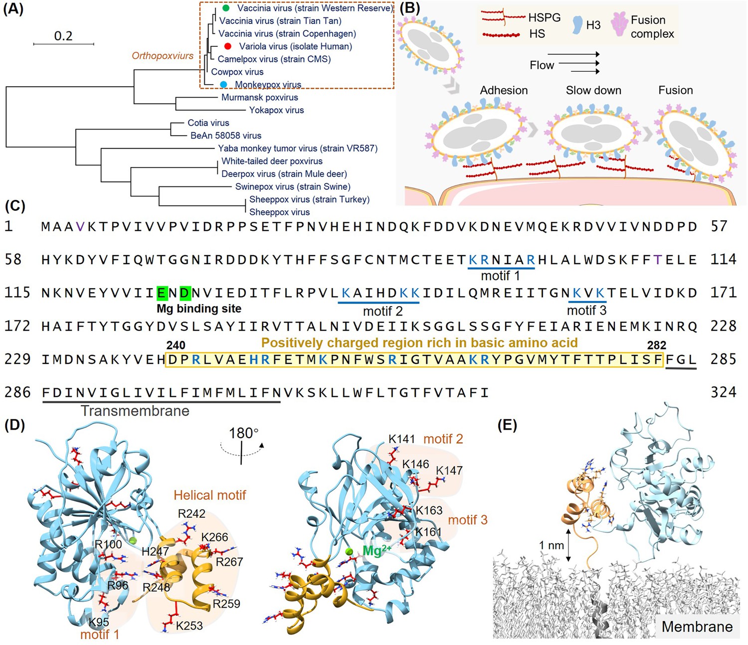
Structural analysis of the H3 protein in monkeypox virus (MPXV).
(A) Phylogenetic tree depicts the evolutionary relationships of H3 within the Poxviridae family, highlighting MPXV (blue circle), variola virus (VARV) (red circle), and vaccinia virus (VACV) (green circle). (B) Schematic of MPXV adhesion to the cell surface. Viral particles bind to cell surface via specific interaction such as between adhesion protein H3 and heparan sulfate (HS), followed by membrane fusion mediated by the fusion complex, allowing entry into the host cell. (C) The amino acid sequence of MPXV H3 shows the newly discovered helical structure (240–282, highlight in yellow), the Mg(II) (green) binding site, and other potential HS binding motifs (blue underlines). (D) AlphaFold2 (AF2) prediction of MPXV H3 structure. The left and right panels show different orientations of the H3 structure (rotated 180°). The blue region corresponds to H3(1–239), which has a homologous crystal structure (VACV H3, PDB code: 5EJ0). The yellow region represents the AF2-predicted structure of H3(240–282), which remains unresolved in the crystal structure of the homologous protein. All potential glycosaminoglycans (GAGs) binding motifs are highlighted with a yellow background. (E) Molecular dynamics (MD) simulation snapshot of H3 on a DPPC (dipalmitoylphosphatidylcholine) membrane. H3 is anchored to the membrane through its transmembrane region (residues 283–306, in gray).
Figure 1—figure supplement 1
Structural prediction protein-membrane modeling of monkeypox virus H3 protein.
(A–C) In the protein cartoon diagram, the colors represent the pLDDT scores output by AlphaFold2 (AF2), ESMFold, and RoseTTAFold2 respectively, with blue indicating a higher prediction confidence. For the AF2 result, the helical domain is displayed in blue, indicating a region where the pLDDT score is greater than 80, signifying a high confidence in structural prediction. (D) Modeling of H3 with DPPC (dipalmitoylphosphatidylcholine) membrane. The blue represents H3(1–239), the yellow represents H3(240–282), the black corresponds to the transmembrane region H3(283–306), and the gray molecules represent DPPC. (E) The minimal distance between helical domain and DPPC membrane during the 500 ns molecular dynamics (MD) simulations.
Figure 1—video 1
Molecular dynamics (MD) simulation trajectories of H3 with DPPC (dipalmitoylphosphatidylcholine) membrane.
Figure 2 with 10 supplements
Identification of heparan sulfate (HS) binding motifs in H3 by molecular dynamics (MD) simulation and docking.
(A–B) Cartoons show docking results of HS with Motifs 1, 2, 3, and the helical domain, respectively. (B) Panels show RMSD (root mean square deviation) values from 1 µs MD simulations, color-coded to match the configurations in (A). (C) Schematics illustrate the reaction coordinate in umbrella sampling, highlighting HS dissociation from H3 with a green force curve. (D) Histogram shows the binding free energies for HS-H3 interactions in Motifs 1, 2, 3, and the helical domain. (E) A free energy landscape map from a 1000 ns REMD (replica exchange molecular dynamics) simulation shows HS binding configurations to the helical and Mg(II) regions. (F) Panel provides salt bridge formation statistics between HS and H3’s basic amino acids, with a bar chart of average formations. (G) A surface plot shows the frequency of salt bridge formations within H3, with areas of frequent formations in blue. (H) Detailed views of HS-H3 interactions, with the left image showing salt bridges and the right image displaying electrostatic interactions with Mg(II). This panel illustrates the impact on HS binding stability to H3 following the removal of Mg(II) during the simulation. (J) The effects of mutating all basic amino acids in the helical domain on the binding stability of HS are shown. (K) The ‘palm-binding’ model is depicted where HS is secured by the helical ‘fingers’ and interacts with the Mg(II)-bound ‘palm’.
-
Figure 2—source data 1
RMSD (root mean square deviation) data used for Figure 2B.
- https://cdn.elifesciences.org/articles/100545/elife-100545-fig2-data1-v1.xlsx
-
Figure 2—source data 2
Force-extension data used for Figure 2C.
- https://cdn.elifesciences.org/articles/100545/elife-100545-fig2-data2-v1.xlsx
-
Figure 2—source data 3
Binding energy data used for Figure 2D.
- https://cdn.elifesciences.org/articles/100545/elife-100545-fig2-data3-v1.xlsx
-
Figure 2—source data 4
Salt bridge data used for Figure 2F.
- https://cdn.elifesciences.org/articles/100545/elife-100545-fig2-data4-v1.xlsx
-
Figure 2—source data 5
RMSD (root mean square deviation) data used for Figure 2I.
- https://cdn.elifesciences.org/articles/100545/elife-100545-fig2-data5-v1.xlsx
-
Figure 2—source data 6
RMSD (root mean square deviation) data used for Figure 2J.
- https://cdn.elifesciences.org/articles/100545/elife-100545-fig2-data6-v1.xlsx
Figure 2—figure supplement 1

Structural formula of heparan sulfate (HS).
The composition of HS used in the main text consists of -[IdoA2S-GlcNS6S-IdoA-GlcNS(3,6S)]5-, containing a total of 20 repeating monosaccharide units.
Figure 2—figure supplement 2
Docking results of H3 with heparan sulfate (HS).
The docking area of HS was confined near different motifs by setting the docking box. The figure displays the docking results for four motifs, with the top four docking outcomes in each motif area selected based on the best scores (kcal/mol) from AutoDock Vina for subsequent molecular dynamics (MD) simulations.
Figure 2—figure supplement 3
Umbrella sampling calculation of the binding free energy of HS-H3.
The conformation of heparan sulfate (HS) binding simultaneously to the helical domain and Mg2+, obtained from replica exchange simulations, was further subjected to umbrella sampling to calculate the binding free energy. The stretching process is illustrated in (A), with the distribution of the reaction coordinate shown in (B). (C) presents the PMF (potential of mean force) profile obtained after calculations using the weighted histogram analysis method (WHAM).
Figure 2—figure supplement 4
Evolution of salt bridge formation in heparan sulfate (HS) during molecular dynamics (MD) simulations.
This represents the variation in the number of salt bridges formed between HS and all basic amino acid side chain of H3 as the simulation progresses. The lighter areas indicate the formation of a greater number of salt bridges.
Figure 2—figure supplement 5
Structure prediction of H3(uncharged) by AlphaFold2 (AF2).
The left panel shows the pLDDT scores derived from the AF2 prediction. In the right panel, the blue region corresponds to H3(1–239), and the yellow region represents H3(240–282). All basic amino acids in H3(240–282) have been mutated to serine.
Figure 2—video 1
Molecular dynamics (MD) simulation trajectories of heparan sulfate (HS) binding to H3 domain 1 and the helical domain.
Figure 2—video 2
Steered molecular dynamics (SMD) simulation trajectories of heparan sulfate (HS) dissociating from H3 in umbrella sampling.
Figure 2—video 3
Trajectories of H3 and heparan sulfate (HS) interactions in replica exchange molecular dynamics simulations (REMD).
Figure 2—video 4
Molecular dynamics (MD) simulation trajectories of the H3-H3 complex after removal of the Mg (II) from H3.
Figure 2—video 5
Molecular dynamics (MD) simulation trajectories of the H3-H3 complex after mutating the positively charged amino acids on the helical domain of H3 to serine.
Figure 3 with 3 supplements
Charge characteristics and structural analysis of H3 protein.
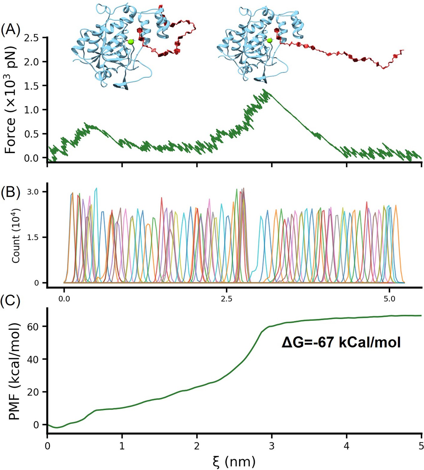
(A) The heatmap shows the amino acid charge distribution in the H3 protein across 66 Poxviridae viruses, following multiple sequence alignment. Blue indicates areas with more positive charges, and red indicates more negative charges. The accompanying curve shows the average charge of all amino acids in Poxviridae H3. (B) Logo plot of the amino acid sequence of the helical region, highlighting the conservation of basic amino acids at specific positions. (C) The surface charge analysis of H3 from the monkeypox virus (MPXV), vaccinia virus (VACV), variola virus (VARV), and cowpox viruses (CPXV) with the helical domain showing a significantly positive charge. (D) Schematic of the single-molecule force spectroscopy unfolding experiment on H3, illustrating the unfolding process of the helical domain (yellow) followed by the main body (blue). (E) Representative curves of H3 unfolding, color-coded to show the helical region (yellow), main body (blue), and full-length (purple) unfolding. (F) Histograms depict the force spectroscopy signals for helical domain (n=139), main body (n=294), and full-length unfolding (n=289), with ΔLc statistics provided. The inset shows a Gaussian fit of unfolding forces.
-
Figure 3—source data 1
Evolutionary analysis data used for Figure 3A.
- https://cdn.elifesciences.org/articles/100545/elife-100545-fig3-data1-v1.xlsx
-
Figure 3—source data 2
Evolutionary analysis data used for Figure 3A.
- https://cdn.elifesciences.org/articles/100545/elife-100545-fig3-data2-v1.xlsx
-
Figure 3—source data 3
Unfolding ΔLc and force data used for Figure 3F.
- https://cdn.elifesciences.org/articles/100545/elife-100545-fig3-data3-v1.xlsx
Figure 3—figure supplement 1
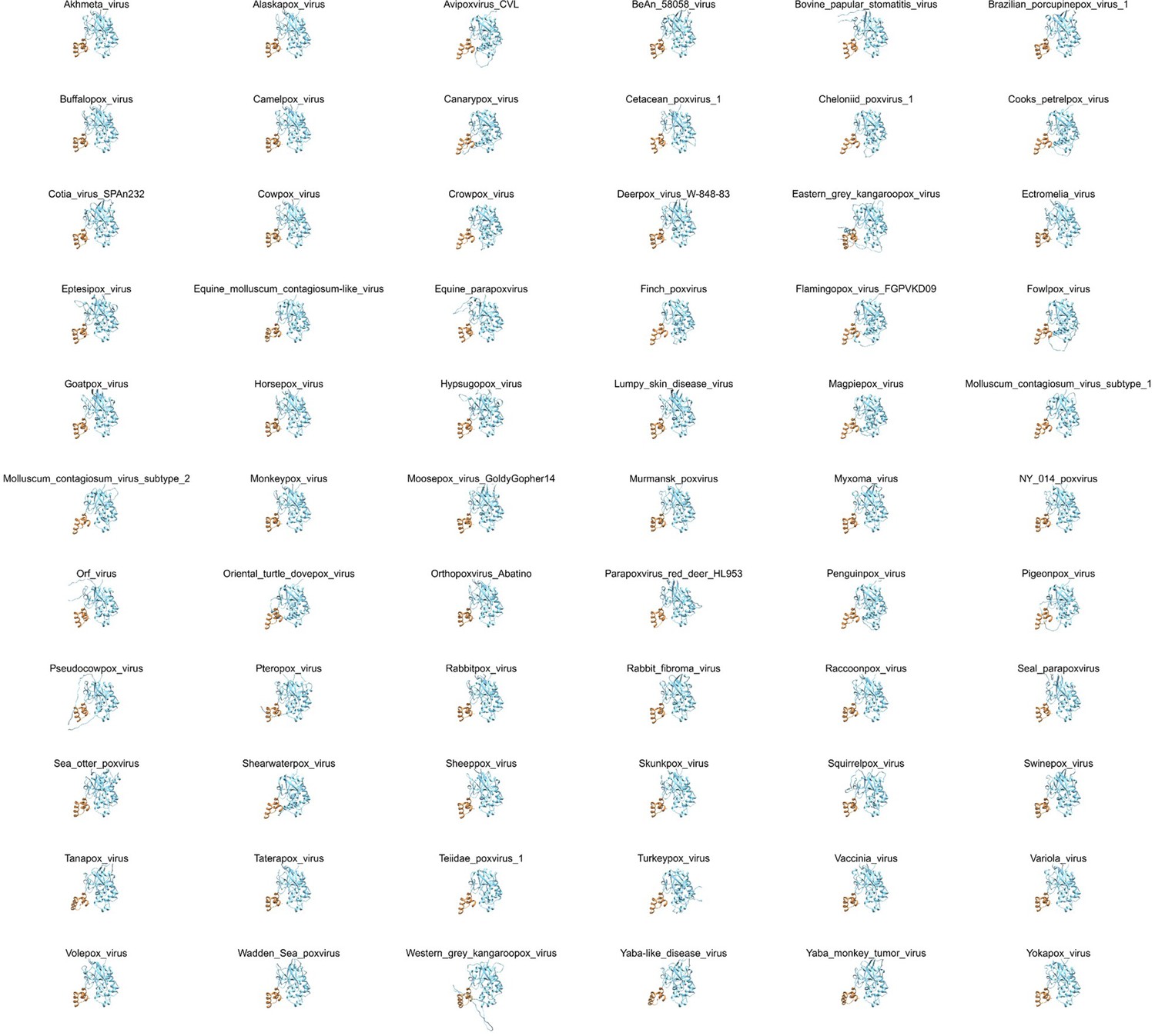
AlphaFold2 (AF2) structural prediction of 66 Poxviridae virus H3 proteins.
The yellow portion represents the helical domain, while the blue portion signifies the main body of H3.
Figure 3—figure supplement 2
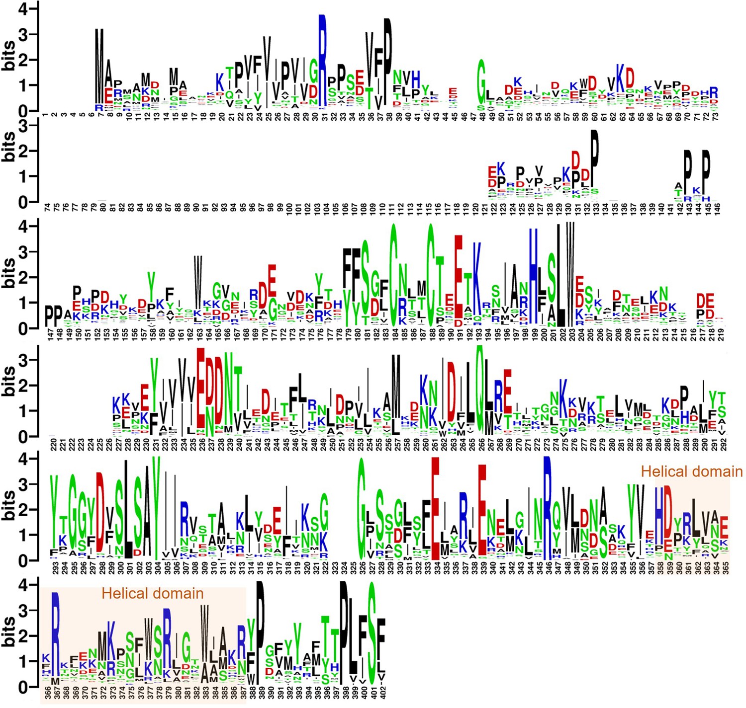
Analysis results of full sequence analysis for 66 Poxviridae virus H3 proteins.
The logo plot illustrates the probability of amino acid occurrence within the H3 sequences, where larger font sizes indicate a higher occurrence probability, denoting greater conservation. Acidic amino acids, basic amino acids, polar amino acids, and non-polar amino acids are represented in red, blue, green, and black, respectively.
Figure 3—figure supplement 3
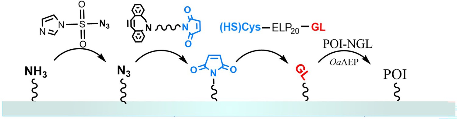
Protein immobilization in atomic force microscopy-based single-molecule force spectroscopy (AFM-SMFS) experiments.
Peptide GL-ELP20-Cys is modified on a glass substrate (or AFM tip) that has been functionalized with maleimide through a Michael addition reaction. The N-terminus GL can undergo an enzymatic ligation reaction with the C-terminus NGL of the target protein in the presence of ligase OaAEP1, thereby immobilizing the target protein, such as Coh-GB1-GB1-H3-NGL and GL-GB1-Doc, on the substrate or AFM tip.
Figure 4
Analysis of the helical domain’s interaction with heparan sulfate (HS) at cellular level.
(A) Schematic of the cell force spectroscopy experiment setup shows three scenarios: wild-type H3 on an atomic force microscopy (AFM) tip interacting with HS on Chinese hamster ovary K1 (CHO-K1) cells, mutation of all basic amino acids in the H3 helical region to serine, and cells treated with HS hydrolase to remove surface HS before testing. (B) Force-extension curves depict interactions for the wild-type (WT), mutant, and control groups, marked with blue and red asterisks for dissociation events. An inset shows the optical microscope positioning the AFM probe. (C) Histograms of dissociation signals comparing the WT, mutant, and control groups, with an inset detailing the surface distribution of dissociation forces. (D) Statistical graph showing binding probabilities for different groups (WT n=18, Uncharged n=17, Control n=12), highlighting significant differences determined by Student’s t-tests (p<1e-5). (E) Flow cytometry (FCM) results illustrate interactions of WT and uncharged H3 fused with eGFP with CHO-K1 cells, alongside GFP control (green) and cell-only control (blank, gray). (F) Statistical analysis of FCM data (n=10), showing significant differences between groups as determined by Student’s t-test. *****, P<1e-5. Error bars indicate SD.
-
Figure 4—source data 1
Unbinding force data used for Figure 4C.
- https://cdn.elifesciences.org/articles/100545/elife-100545-fig4-data1-v1.xlsx
-
Figure 4—source data 2
Atomic force microscopy-based single-molecule force spectroscopy (AFM-SMFS) unbinding probability data used for Figure 4D.
- https://cdn.elifesciences.org/articles/100545/elife-100545-fig4-data2-v1.xlsx
-
Figure 4—source data 3
ECM binding data used for Figure 4F.
- https://cdn.elifesciences.org/articles/100545/elife-100545-fig4-data3-v1.xlsx
Figure 5 with 11 supplements
Inhibitor design targeting the H3-HS interaction and efficacy of AI-PoxBlock723.
(A) Diagrams depict protein inhibitors designed to target the H3 helical region, created using RFdiffusion. Sequences capable of folding into the target scaffold structures were generated using ProteinMPNN, and were validated through AlphaFold2 (AF2), followed by 500 ns molecular dynamics (MD) simulations for structural stability and interaction scoring. (B) Flow cytometry (FCM) analysis demonstrates the inhibitory effect of AI-Poxblock723 at various concentrations (0, 10, 50, and 100 μM, x-axis, n=5). The control group consisted of 2 μM H3-eGFP without the inhibitor, with the relative fluorescence intensity normalized to 1. (C) Biolayer interferometry (BLI) confirms direct interaction between AI-Poxblock723 and the H3 helical domain. (D) Graphs display the inhibitory effect of the indicated AI-Poxblocks on monkeypox virus (MPXV) infection of Vero E6 cells, with quantitative analysis of virus-infected foci provided on the right. (E–F) BALB/c mice were infected intranasally with 4×10⁵ FFU (focus-forming unit) MPXV and treated with single dose of AI-PoxBlock723 (10 mg/kg) or phosphate buffer solution (PBS) immediately after challenge (n=5). Infectious MPXV particles and MPXV viral loads in mice lungs at 4 days post-infection (dpi) were determined by focus-forming assay (E) and quantitative polymerase chain reaction (qPCR) (F). Error bars indicate SEM and statistical significance was evaluated using Student’s t-test (B, E). *P < 0.05, ***P < 0.001.
-
Figure 5—source data 1
Inhibitory effect data used for Figure 5B.
- https://cdn.elifesciences.org/articles/100545/elife-100545-fig5-data1-v1.xlsx
-
Figure 5—source data 2
Biolayer interferometry (BLI) data used for Figure 5C.
- https://cdn.elifesciences.org/articles/100545/elife-100545-fig5-data2-v1.xlsx
-
Figure 5—source data 3
Inhibitory effect data used for Figure 5D.
- https://cdn.elifesciences.org/articles/100545/elife-100545-fig5-data3-v1.xlsx
-
Figure 5—source data 4
Inhibitory effect data used for Figure 5E.
- https://cdn.elifesciences.org/articles/100545/elife-100545-fig5-data4-v1.xlsx
-
Figure 5—source data 5
Inhibitory effect data used for Figure 5F.
- https://cdn.elifesciences.org/articles/100545/elife-100545-fig5-data5-v1.xlsx
Figure 5—figure supplement 1
Artificial design of H3 inhibitors.
The gray structure represents the protein backbone structure designed by RFdiffusion, while the purple structure is the sequence generated by ProteinMPNN based on that backbone, followed by complex prediction from AlphaFold2 (AF2). The two structures align well, with an RMSD (root mean square deviation) less than 1.5 nm.
Figure 5—figure supplement 2
AlphaFold2 (AF2)-predicted structures of the H3 and inhibitor complexes.
From left to right are AI-Poxblock302, AI-Poxblock602, AI-Poxblock614, AI-Poxblock723, and AI-Poxblock761. All inhibitors are depicted in purple, and the helical domain of H3 are marked in yellow.
Figure 5—figure supplement 3
Molecular dynamics (MD) simulations of H3-inhibitor complex.
The H3 and inhibitor complex underwent a 500 ns MD simulation, resulting in the variation of RMSD (root mean square deviation) (nm) over time (ns).
Figure 5—figure supplement 4
Flow cytometry analysis demonstrates the efficacy of the inhibitors.
The graph shows relative fluorescence intensity, indicating that in the presence of 10 μM AI-Poxblock723, the binding of H3(1–282)-eGFP to Chinese hamster ovary K1 (CHO-K1) cells is reduced compared to the control group (gray).
Figure 5—figure supplement 5
AI-Poxblock723 and H3(1–239) biolayer interferometry (BLI) experiment.
BLI curves of three concentrations of H3(1–239) (20,000 nM, 10,000 nM, and 2500 nM) with AI-Poxblock723 loaded on the sensor. The curves could not be fitted to obtain the KD value.
Figure 5—figure supplement 6
Circular dichroism (CD) spectroscopy of AI-Poxblock723.
CD spectroscopy verifies the designed inhibitor with an α-helical structure.
Figure 5—figure supplement 7
Sequence comparison of the H3 helical domain among representative orthopoxvirus strains monkeypox virus (MPXV), vaccinia virus (VACV), variola virus (VARV), and cowpox virus (CPXV).
Basic amino acid residues are highlighted in blue, and aa differences relative to the MPXV sequence are shaded in yellow.
Figure 5—figure supplement 8
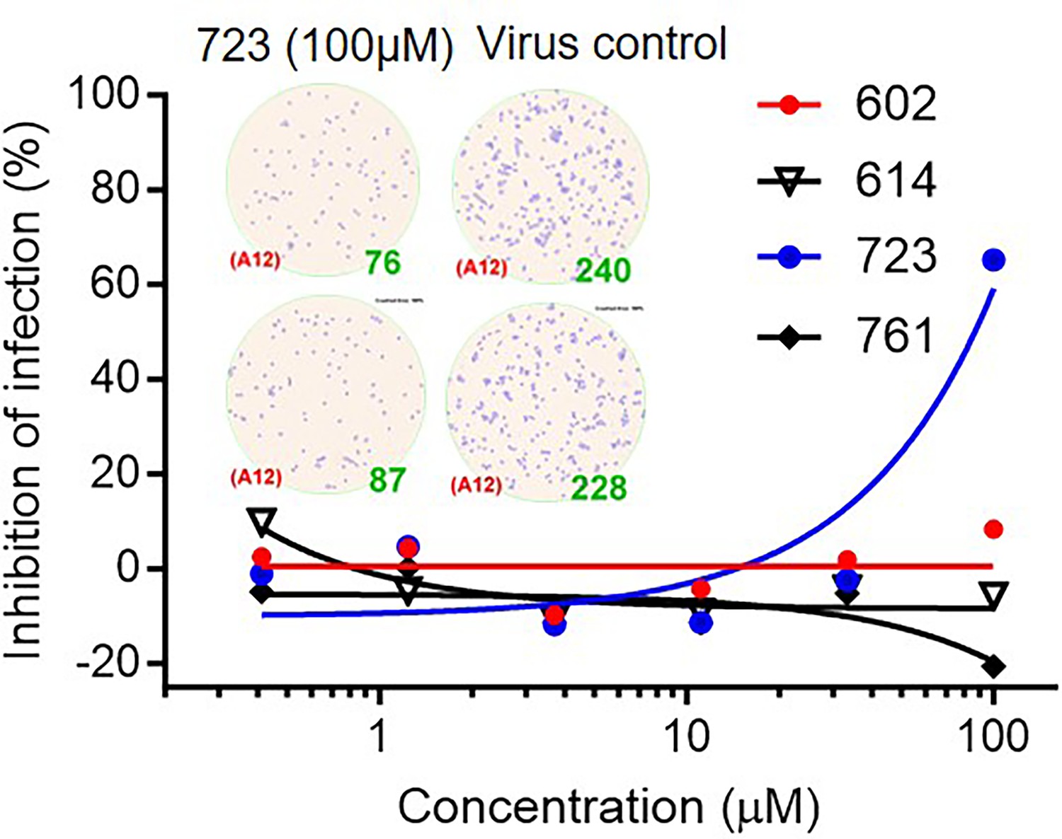
The inhibitory effect of inhibitors on vaccinia virus (VACV) infection of Vero E6 cells.
Virus-infected foci and counts were shown as inset.
Figure 5—figure supplement 9
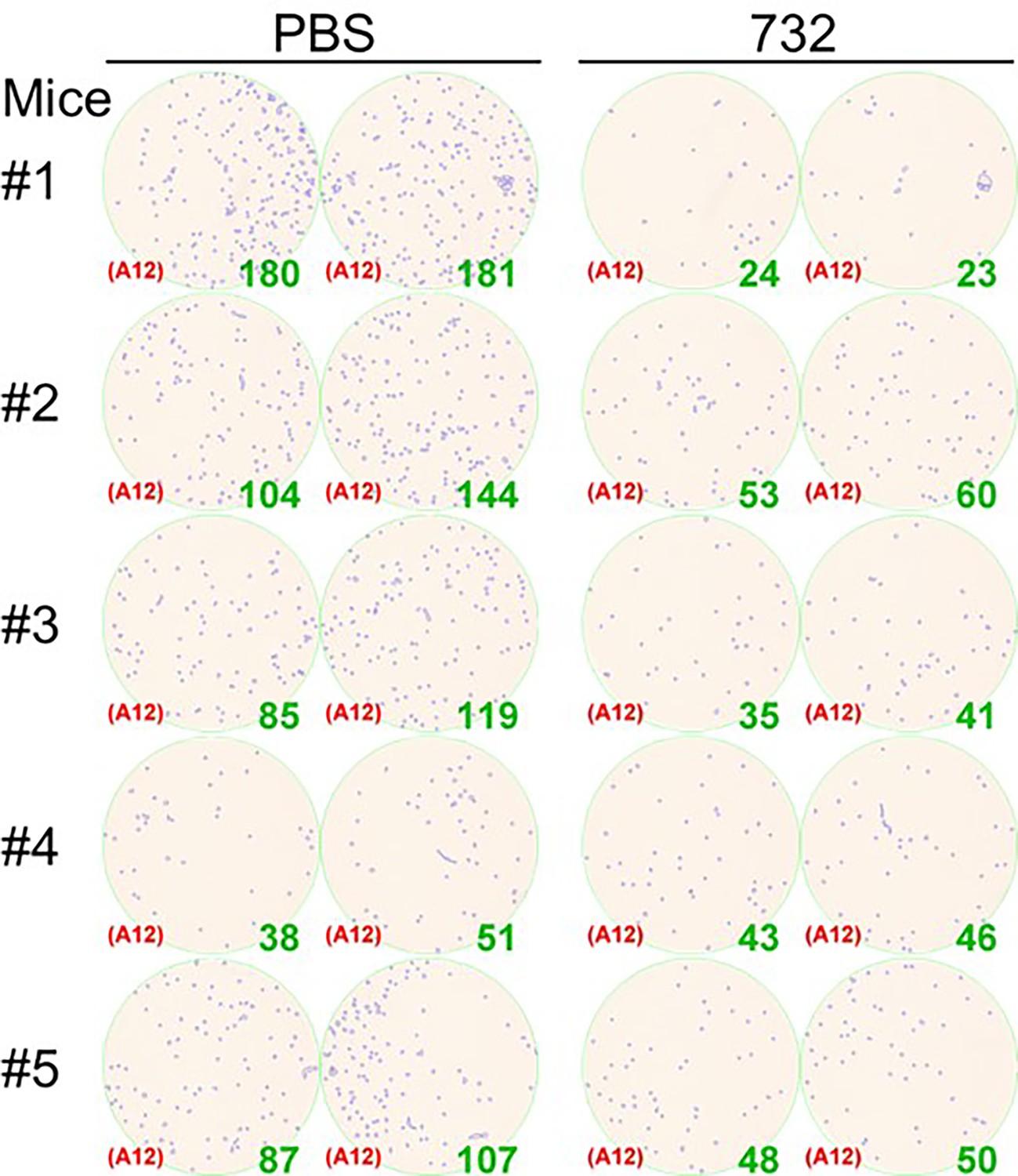
Titration of the monkeypox virus (MPXV) infectious particles in mice lungs 4 days post-infection.
Virus-infected foci and counts were shown as inset.
Figure 5—figure supplement 10
Secondary structure characterization of H3(240–279).
(A) AlphaFold2 prediction result of H3(240–279). (B) Circular dichroism (CD) results and secondary structure prediction of H3(240–279).
Figure 5—video 1
Molecular dynamics (MD) simulation trajectories of the AI-Poxblock723 complex.
Additional files
Download links
A two-part list of links to download the article, or parts of the article, in various formats.
Downloads (link to download the article as PDF)
Open citations (links to open the citations from this article in various online reference manager services)
Cite this article (links to download the citations from this article in formats compatible with various reference manager tools)
Discovery of a heparan sulfate binding domain in monkeypox virus H3 as an anti-poxviral drug target combining AI and MD simulations
eLife 13:RP100545.
https://doi.org/10.7554/eLife.100545.3


