Structure of a Holliday junction complex reveals mechanisms governing a highly regulated DNA transaction
- Brown University, United States
- Brandeis University, United States
- Janelia Research Campus, Howard Hughes Medical Institute, United States
- University of Pennsylvania, United States
Figures
Figure 1

Integration and excision of the λ viral chromosome into and out of the bacterial host chromosome is highly directional and tightly regulated.
(A) Formation of the integrated prophage. In those infected cells where the decision has been made not to replicate the viral DNA, the circularized supercoiled viral DNA (black lines) is inserted into the bacterial chromosome (curly red lines) at a specific site (called attB or BOB’) located between the gal and bio genes (Campbell, 1963). This insertion, integrative recombination, involves cutting the viral DNA at a specific site (called attP or P’C’OCP) and joining these cut ends to the cut ends of the bacterial chromosome in attB. The cutting, recombining, and resealing of viral and bacterial DNA generates new DNA sequences forming the junctions between bacterial and integrated viral DNA. These junction sequences, called attL (BOC’P’) and attR (PCOB’) on the left and right respectively, are themselves substrates for the cutting, recombining, and resealing reactions that will, sometime in the future, remove (excise) the viral DNA from the host chromosome and thereby regenerate the viral attP and bacterial attB sequences. The integrated provirus chromosome is stably inherited, with almost all of its genes repressed, for many bacterial generations. Upon instigation by the appropriate physiological signals, the viral chromosome is excised, replicated, and inserted into viral particles which are released into the environment. The integrative reaction requires the virally-encoded integrase protein (Int) and the bacterial accessory protein Integration Host Factor (IHF). The excisive reaction additionally requires the virally encoded accessory protein Xis (which also inhibits the integrative reactions). Both reactions are stimulated by the bacterial accessory protein Fis. (See Panel C for DNA binding sites of all the proteins and their respective roles in each reaction). Both reactions proceed through a four-way DNA junction called a Holliday junction (HJ) (see Panel B for details of these DNA strand exchanges) (reviewed in [Landy, 2015]). (B) The Holliday junction intermediate. Cutting, recombining, and resealing DNA during recombination proceeds by two pairs of sequential single-strand DNA exchanges that are staggered by seven base pairs that are identical in all four att sites; they are referred to as the 'overlap' region (O). The molecular details of this recombination are common to all reactions catalyzed by the large family of tyrosine recombinases (except for the size of the O regions and the order of strand exchanges), as first characterized for λ Int, Cre, Flp, and XerC/D (reviewed in [Van Duyne, 2015]). It proceeds in the absence of exogenous energy via the formation of high-energy covalent 3’phospho-tyrosine intermediates in the active site of each Int protein. Illustrated here is the pathway for integrative recombination; it would be identical for the excisive reaction but the substrates (left panel) would be attL and attR, leading to attP and attB products (right panel). Viral and bacterial DNAs are denoted as in panel A. (i) The attP (C’OC) and attB (BOB’) sites are aligned anti-parallel with respect to their identical overlap sequences. (ii) The first pair of exchanges, always at the C (green) and B (blue) core sites, is initiated by formation of 3’ phospho-tyrosine linkages (with Tyr342) and 5’ OH termini. (iii) The 5’ OH terminus generated by the cleavage at C attacks the phospho-tyrosine linkage at B to regenerate a new B–C’ strand (orange arrow head). Concomitantly, the 5’ OH from the cleavage at C attacks the phospho-tyrosine linkage at B to regenerate a new B'–C strand (orange arrow head). Together, this pair of single strand exchanges, at one boundary of the overlap region, forms the four-way DNA (HJ) intermediate. (iv) A similar pair of single strand cleavage, exchange, and resealing reactions is executed by the Ints at C’ (brown) and B’ (purple) on the other side of the overlap region. (v) As a result of the two sequential pairs of single-strand exchanges, all four DNA strands have new junction sequences and the HJ is resolved to recombinant products attL (C’OB) and attR (COB’). C) Additional complexity, in the P’ and P arms, confers regulation and directionality to the λ Int reaction. In contrast to the 'simple' Cre and Flp tyrosine recombinases, λ Int (and more than a thousand viral cousins in the public data bases) has two DNA binding domains, as shown in Figure 2. The carboxy-terminal domain of Int (CTD) binds at the four sites of DNA cleavage (called core-type sites; blue boxes) and catalyzes the chemistry of DNA cleavage and rejoining; this domain and the core-type sites (B, B’, C’ and C) are analogous, and very similar, to the Cre and Flp enzymes and their respective DNA targets sites (see panel B). In λ Int an additional small DNA binding domain at the amino terminus (NTD) binds with high affinity to a different family of DNA sequences (arm-type sites) (green boxes) distant from the sites of DNA cleavage and located in the P’ and P arms of viral DNA (adjacent to C’ and C, respectively). To enable the ('hetero-bivalent') Int to bind simultaneously to both of its DNA targets the core- and arm-type DNA sites are interposed by binding sites for the accessory DNA bending proteins, IHF (yellow boxes, H1, H2, and H’), Xis (gold boxes, X1, X1.5, X2), and Fis (magenta). The DNA bending proteins bring the core- and arm-type sites into close proximity and also serve as essential elements in forming the large multi-protein recombination complexes. Two distinct but overlapping ensembles of binding sites are employed (solid boxes) to generate either the integrative or excisive recombinogenic complexes (reviewed in [Landy, 2015]). (For the patterns of Int bridging between core- and arm-type sites in each of the complexes see Figure 2).
Figure 2
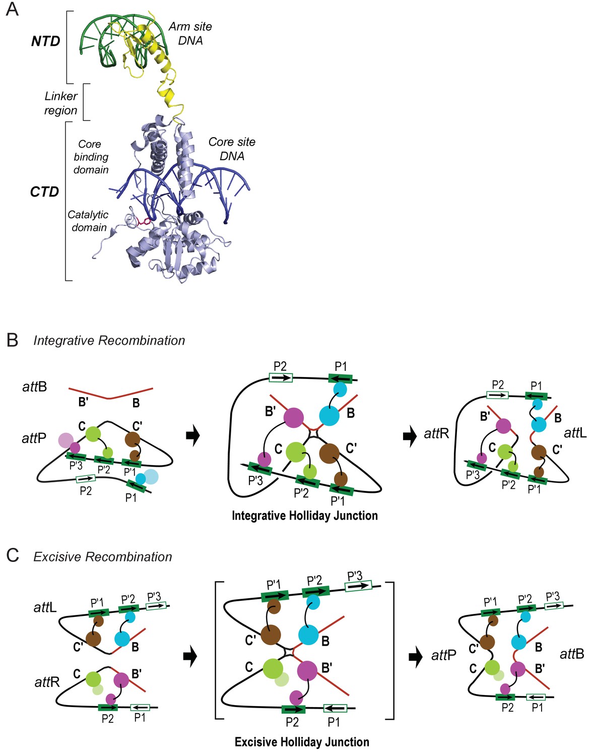
Patterns of specific Int bridges between core- and arm-type DNA binding sites.
(A) The amino-terminal domain (NTD) of Int (yellow) binds to one of the five arm-type DNA sites (green) via a helix-turn-helix recognition motif. It is joined via a flexible 10 residue linker region to the carboxy-terminal domain (CTD) (light blue), which is composed of two smaller domains (the core-binding (CB) and catalytic domains) joined by a 12 residue linker. The CTD binds to core-type DNA sites (blue) via a C-clamp motif; the distal domain of the C-clamp contains the nucleophile Tyr-342 (red) and those residues comprising the catalytic site for DNA cleavage and ligation. The CTD is analogous, and very similar in structure and function, to the well-studied monovalent recombinases, Cre, Flp, and XerC/D. (B) Integrative recombination depends upon four Int bridges, as determined previously (Tong et al., 2014). In the attP and attB substrates (left-most panel) only two of the four bridges are formed prior to synapsis; the accessory DNA bending proteins have been omitted for clarity (see Figure 1C). The coloring scheme for the Ints bound to different arm-type sites is the same as that used in all of the following figures. (C) Excisive recombination involves a different pattern of Int bridges (Tong et al., 2014) and, as shown in Figure 1C, a different ensemble of DNA bending proteins. The HJ intermediate of this reaction (brackets) was purified and used for single particle cryo-electron microscopy, as described in the text.
Figure 3

Isolation and single particle electron cryo-microscopy of the Holliday junction recombination intermediate.
(A) Native polyacrylamide gel electrophorograms of the recombination reactions prior to and after sucrose gradient purification. Recombination reactions between attL and attR partners designed to trap the HJ intermediate (see Figure 2) were treated with 0.0035% glutaraldehyde for 10 min, quenched with 0.3 M glycine and concentrated by ultrafiltration. The concentrated 100 μL samples were loaded onto a 2 mL sucrose gradient (22%–40% sucrose, 10 mM Tris, pH 8, 1 M Betaine) and centrifuged for 16 hr at 4°C. After examining each of the 100 µl fractions by native PAGE the purest fractions were pooled, concentrated, and subjected to a second round of centrifugation. The samples were either immediately frozen in liquid nitrogen for storage or used for plunging grids (see Materials and methods for details). (B) Electron micrograph of ice-embedded Holliday junction complexes. Some complexes used for further processing are encircled. Scale bar = 300 Å. (C) Some 2D class averages obtained from 66,033 particles that were selected from 1359 micrographs. Different views of the complex are apparent. Some of the views clearly show loops, other crosses. (D) Different views of the 3D reconstruction of the Holliday junction complex at 11 Å resolution calculated from 10,956 particles and sharpened with a B-factor of -2500 Å2 (see Materials and methods for details). Scale bar = 100 Å.
Figure 4
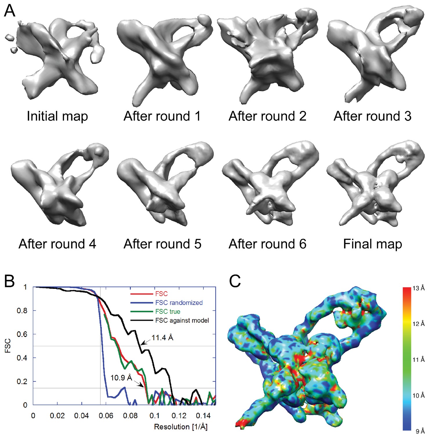
Electron cryo-microscopy refinement and 3D classification.
(A) Different stages of refinement and classification using FREALIGN (Lyumkis et al., 2013). Reconstructions at each stage are shown. The initial map was generated from 2D class averages (Figure 3C) using EMAN2’s initial model procedure (Tang et al., 2007). Subsequent maps resulted from several rounds of refinement and 3D classification in FREALIGN. The best-scoring reconstruction from each round was used to initialize the next round. The final reconstruction contained 10,956 particles. (B) Resolution estimation of the final reconstruction using the Fourier Shell Correlation (FSC) method. The red curve (labeled FSC) was calculated using the two reconstructions obtained from half the data each and masked using a tight mask that left a margin around the reconstructed density of about 15 Å. The blue curve (FSC randomized) was calculated using a second set of reconstructions obtained from data phase-randomized beyond a resolution of 18 Å. This curve was used to correct the first curve for any masking effects (Chen et al., 2013), yielding the final green curve (FSC true). The black curve (FSC against model) was calculated between the final map and a map derived from the atomic model presented in this study. The vertical line indicates 18 Å resolution, the limit beyond which no data was used for refinement and classification. The horizontal lines indicate values of 0.143, the FSC threshold used to assess the resolution of the map (Rosenthal and Henderson, 2003), and 0.5, the corresponding FSC threshold when comparing an experimental map against a noise-free model. Both ‘FSC true’ and ‘FSC against model’ suggest a resolution of about 11 Å. The FSC data are shown in Figure 4—source data 1 and 2. (C) Local resolution map calculated using ResMap (Kucukelbir et al., 2014). The resolution is fairly uniformly indicated as 11 Å, except for small regions within the Int tetramer and at one of the IHF heterodimer sites, indicating lower resolution and higher structural variability in these regions.
-
Figure 4—source data 1
FSC data in Excel format.
FSC, randomized FSC, and true FSC are tabulated as a function of resolution.
- https://doi.org/10.7554/eLife.14313.007
-
Figure 4—source data 2
FSC data in csv format.
FSC, randomized FSC, and true FSC are tabulated as a function of resolution.
- https://doi.org/10.7554/eLife.14313.008
Figure 5

Model and reconstructed density for the λ excision complex.
(A) View from the 'top' of the complex, illustrating the IHF-mediated bends at H2 and H' and the close, parallel trajectory of the P and P' arms. Unmodeled density that could be occupied by Int-C NTD is indicated by an arrow. (B) View from the bottom of the complex, highlighting the catalytic domains of the Int tetramer. The Int subunits are labeled according to the core half-sites where they are bound (B, B', C, and C'). IHF heterodimers and Xis subunits are indicated. In the schematic representations shown below the structural models, the DNA strands near the junction centers are omitted for clarity.
Figure 6
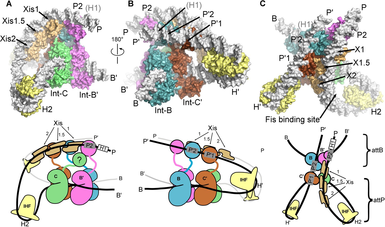
The λ excision complex structure.
(A) View towards the attR-derived half of the complex, where the path of the P arm can be seen. A sharp IHF (yellow) directed bend at the H2 site, combined with the cooperative binding and bending by three Xis molecules (gold) and the Int subunit bridging between the B' and P2 sites (magenta), redirects the P arm over the top of the Int tetramer. The Int-C NTD is not present in the model because it could not be unambiguously fit into EM density (approximate location is indicated in the corresponding cartoon). B) View towards the attL-derived half of the complex, where IHF bound at the H' site sharply bends the P' arm and enables Int subunits to bridge between the C' and P'1 sites (brown) and between the B and P'2 sites (blue). (C) View from the top of the excision complex, where the P'-arm (from attL) and P-arm (from attR) run nearly parallel and close to one another. An intimate interface is formed between the Xis subunits and the Int-C' and Int-B NTDs. The unoccupied, but accessible binding site for Fis is indicated. In the schematic views of the excision complex shown below the structural models, the DNA strands near the junction center are omitted for clarity. For reference, the brackets labeled attP/attB indicate the relative positions of the excision products. See Video 1 for multiple views of the excisive complex structure and isolation of individual subunits.
Figure 7
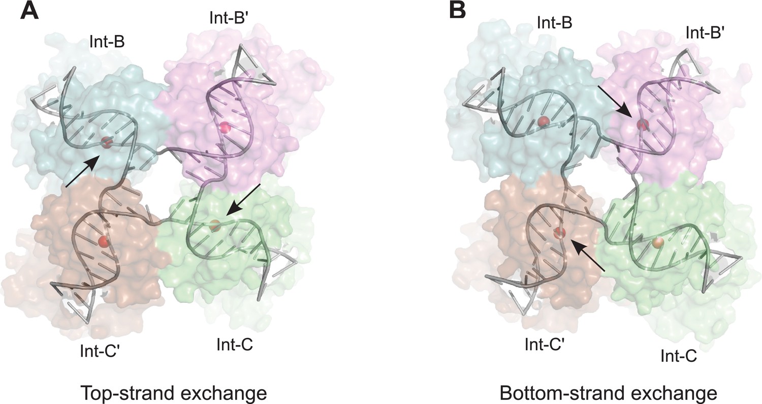
Model for isomerization of HJ intermediate.
The core HJ complex is fit to the reconstructed density, based on structure 1Z1G (Protein Data Bank) (Biswas et al., 2005). (A) The HJ isomer corresponding to a top-strand cleavage configuration, where the Int subunits bound at the B and C half-sites are activated for cleavage and strand exchange. B) Alternative isomer, where Int-B' and Int-C' are activated for cleavage of the bottom strands. Scissile phosphates (red spheres) are closer together in the active subunits compared to the inactive ones. Arrows indicate the activated phosphodiesters. The interconversion between (A) and (B) involves migration of the branch point by one base-pair, with only minimal changes at the ends of the duplex arms. An animation that illustrates the HJ isomerization is provided as Video 2.
Figure 8
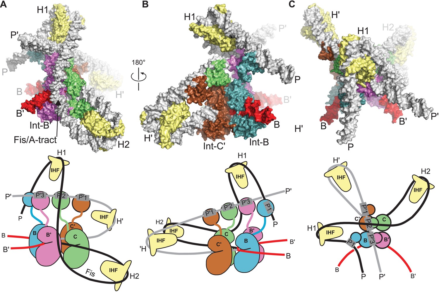
Model of the λ integration complex.
(A) View towards the B'–C face of the complex, where the trajectory of the P arm can be seen. IHF bending at the H2 site, combined with an A-tract bend at the Fis site and additional bending provided by negative supercoiling, directs the P arm over the top of the Int tetramer and over the P' arm. IHF-bending at the H1 site re-directs the P arm down along the opposite face of the tetramer. (B) View towards the C'–B face of the complex, showing Int-B bridging between the B core site and the P1 site. The catalytic and CB domains of Int-B wrap around the opposite face of the attB helix (with respect to the Int bound at the B' site). This arrangement, which is facilitated by the flexible P1 tether, must be accommodated during synapsis, as described in the text and Figure 9. The nearly linear arrangement of NTDs bound at P'1, P'2, and P'3 of the P' arm can also be seen. (C) View from the top of the integration complex. Schematic drawings of the integrative complex are shown below the structural models, where the P arm is black and the P' arm gray. The DNA connectivity at the HJ center is omitted for clarity; consequently the junction between the P arm (black) and P' arm (gray) is not visible. The bend directions of the core sites are opposite to those shown in Figure 6 for the excision complex (e.g., compare the C–C' bend in (C) vs. Figure 6C), underscoring that integration and excision are not the mechanistic reverses of one another.
Figure 9
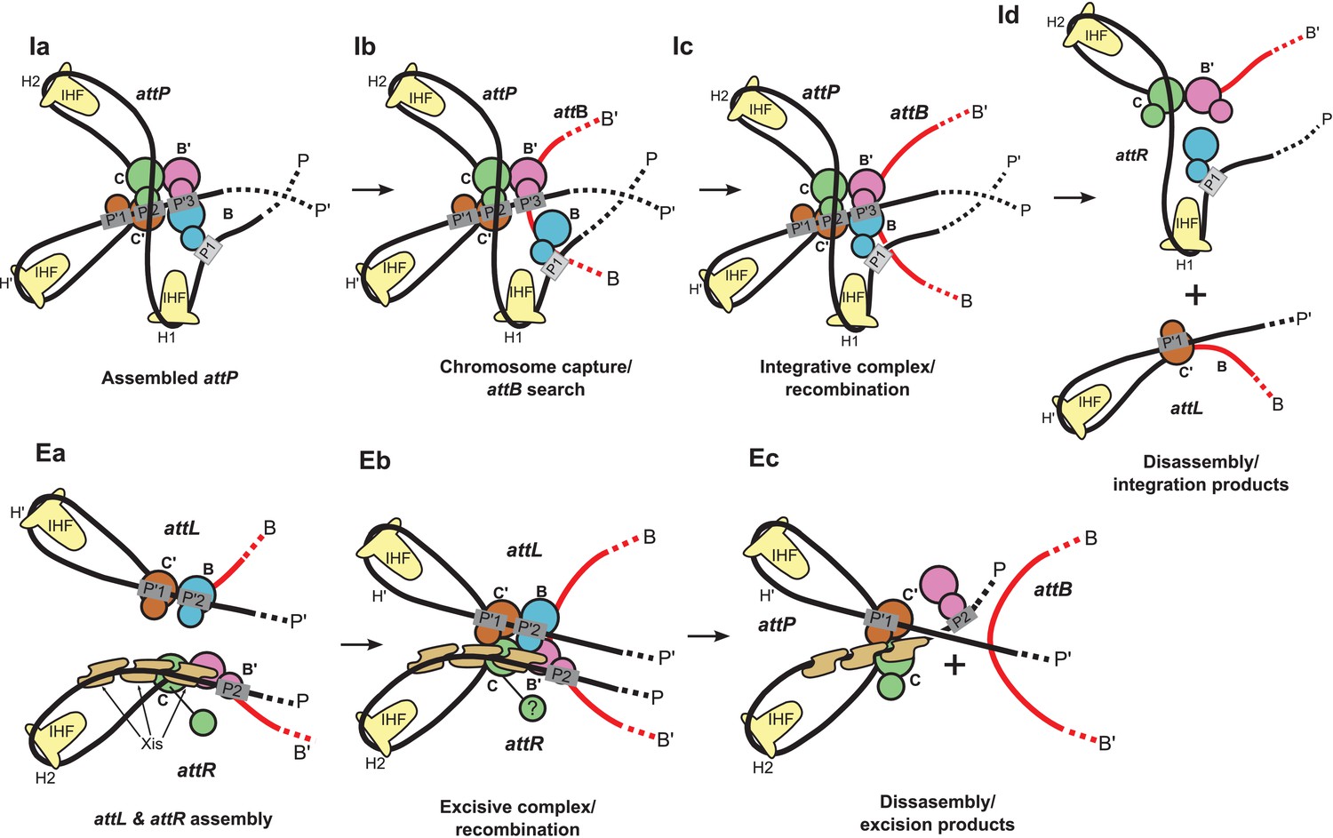
Schematic of the λ integration (Ia–Id) and excision (Ea–Ec) pathways, based on the structural models presented here.
(Ia) In the presence of Int and IHF (but not Xis), an integration complex is assembled on supercoiled attP. We suggest that the Int-B CTD (blue) transiently associates with the Int-C' and Int-B' CTDs (brown & magenta) to form a tetrameric complex. (Ib) The P arm of the integration complex can swing open to test and engage candidate attB sequences and thereby deliver Int-B to the B site on the opposite face of the attB duplex, consistent with the implications of biochemical and genetic results (Seah et al., 2014; Tong et al., 2014) and the especially high affinity of Int NTD for P1 (Sarkar et al., 2002). (Ic) Stable attB binding leads to HJ formation and resolution. (Id) Disassembly results in unstable attR (no bridges) and attL (one bridge) complexes. (Ea) AttL forms a synapsis-competent complex with the two Int bridges, P’1-C’ and P’2-B. In the presence of Xis, attR forms a synapsis-competent complex, due to bending of the P-arm and formation of an Int bridge at P2. Note that the C'-B and C-B' core sites are bent in the opposite directions compared to the integration products shown in (Id). (Eb) Xis mediates formation of a synaptic complex, where recombination can occur. (Ec) Disassembly results in an unstable attP complex containing only one Int bridge. Xis competes with formation of the integration complex shown in (Ia). In panels (Ic) and (Eb), the DNA strands near the center of the complex are omitted for clarity.
Videos
Video 1
The bacteriophage λ excisive HJ intermediate.
Multiple views of the excisive complex are shown. The complex is stripped of all proteins to illustrate the path of the DNA arms as they loop around the 4-way junction. IHF, Xis, and Int subunits are added individually to the DNA to help visualize their structural and functional roles. The assembly sequence shown is for visualization only; nothing is implied regarding the actual order of addition or assembly during λ excision.
Video 2
Isomerization model for the λ HJ intermediate.
The core HJ is shown switching between the isomers described in Figure 7. This type of isomerization could occur within the core of the recombination complex, without large changes in positions of the attached arms.
Tables
Table 1
FRET vs. EM model distances in the λ excisive recombination complex. R(FRET) values were determined by Seah et al. (2014) using in-gel fluorescence measurements for dye pairs whose positions were designed in the absence of a model for the λ excision complex architecture. Dyes positioned at sites 4,5,6,7,11, and 12 are predicted to be largely free from steric interference based on the EM structure. The FRET pairs involving these positions are in the first group below. Dyes positioned at site 3 (second group) and site 8 (third group) are predicted to have steric conflicts between the dye and the excision complex. Four additional sites (1,2,9, & 10) used in the study are on extended P and P' arms not present in the construct used for EM studies. See Seah et al. (2014) for descriptions of the site position nomenclature.
| Position i | Position j | R (FRET) (Å) | R (FRET) Model) (Å) | R (EM Model) (Å) |
|---|---|---|---|---|
| 7 [P+50T] | 6 [P+17B] | 56 | 57 | 50.0 |
| 4 [P-58B] | 5 [P-15T] | 70 | 72 | 70.6 |
| 5 [P-15T] | 12 [B+17B] | 76 | 77 | 78.8 |
| 4 [P-58B] | 6 [P+17B] | 76 | 70 | 67.9 |
| 5 [P-15T] | 6 [P+17B] | 89 | 80 | 81.1 |
| 6 [P+17B] | 11 [B-15T] | 93 | 81 | 85.3 |
| 7 [P+50T] | 4 [P-58B] | 99 | 125 | 108.9 |
| 11 [B-15T] | 12 [B+17B] | 103 | 86 | 82.5 |
| 3 [P-118T] | 12 [B+17B] | 80 | 69 | 64.1 |
| 3 [P-118T] | 5 [P-15T] | 82 | 77 | 95.3 |
| 3 [P-118T] | 11 [B-15T] | 99 | 108 | 100.0 |
| 8 [P+79B] | 3 [P-118T] | 56 | 56 | 41.4 |
| 8 [P+79B] | 11 [B-15T] | 74 | 65 | 75.2 |
| 8 [P+79B] | 5 [P-15T] | 96 | 109 | 81.3 |
| 8 [P+79B] | 6 [P+17B] | 96 | 107 | 85.4 |
| 8 [P+79B] | 4 [P-58B] | 108 | 158 | 124.8 |
| 8 [P+79B] | 12 [B+17B] | 116 | 73 | 68.2 |
Download links
A two-part list of links to download the article, or parts of the article, in various formats.
Downloads (link to download the article as PDF)
Open citations (links to open the citations from this article in various online reference manager services)
Cite this article (links to download the citations from this article in formats compatible with various reference manager tools)
Structure of a Holliday junction complex reveals mechanisms governing a highly regulated DNA transaction
eLife 5:e14313.
https://doi.org/10.7554/eLife.14313


