The Glide/Gcm fate determinant controls initiation of collective cell migration by regulating Frazzled
- Institut de Génétique et de Biologie Moléculaire et Cellulaire, France
- Centre National de la Recherche Scientifique, UMR7104, France
- Institut National de la Santé et de la Recherche Médicale, U964, France
- Université de Strasbourg, France
- Tata Institute for Fundamental Research, India
Figures
Figure 1 with 1 supplement
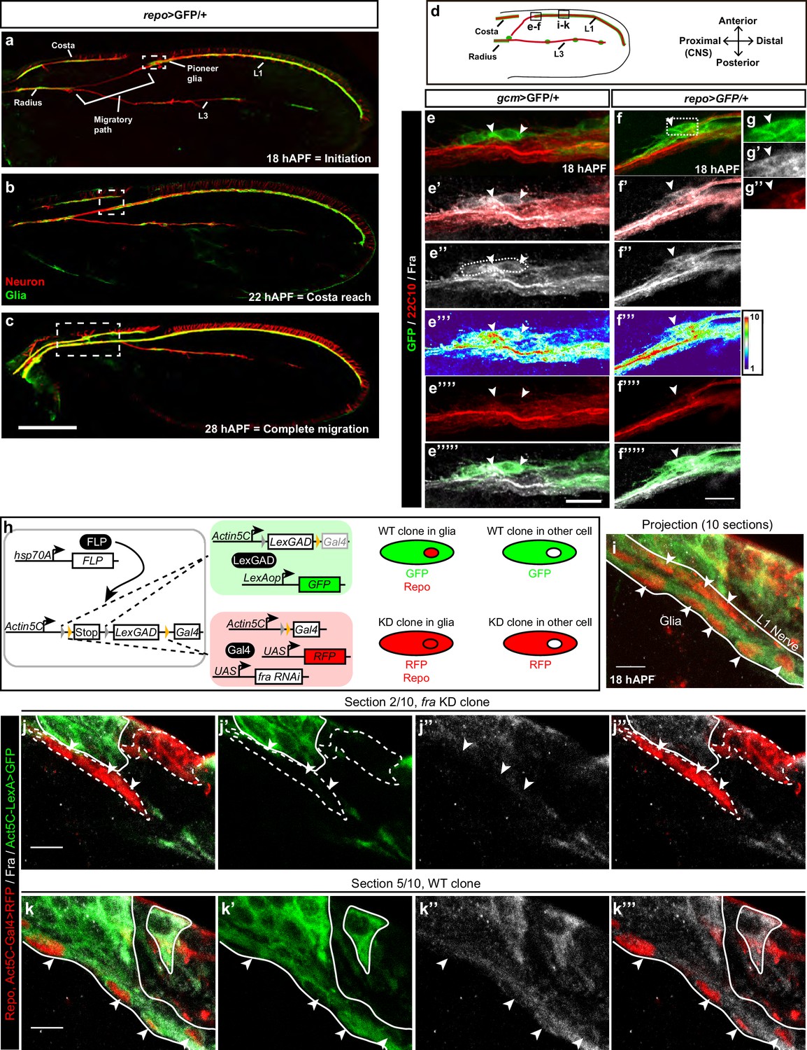
Expression of Fra in wing glia.
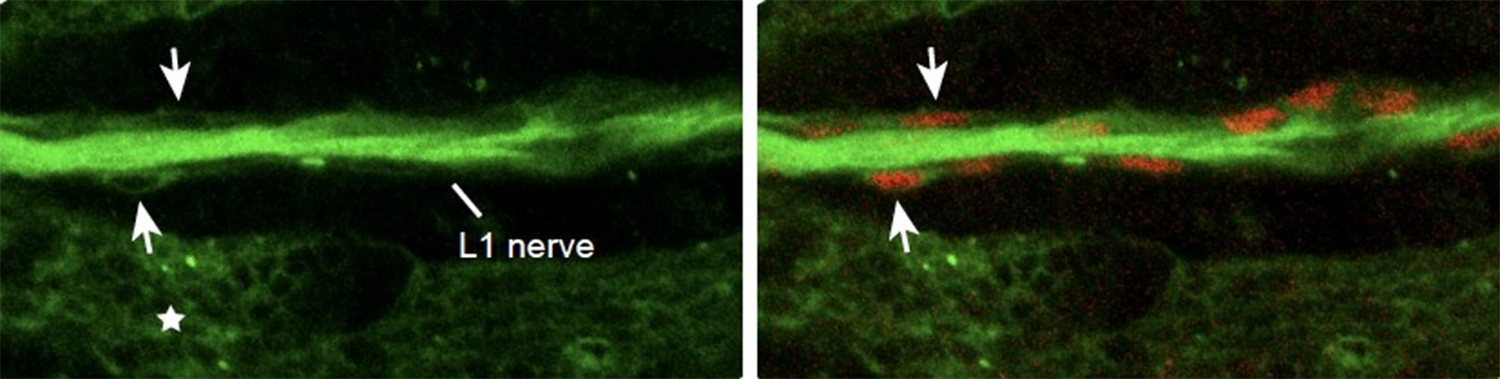
(a–c) Immunolabeled repo>GFP wing (glia in green: anti-GFP; neurons in red: anti-22c10) at different stages. (a) Initiation of migration, (b) reaching the level of the costa, and (c) migration completion. (d) Schematic of a 18 hAPF developing Drosophila wing, insets indicate the regions shown in panels (e–f’’’’’) and panels (i–k’’’). L1 and L3 indicate L1 and L3 nerves. (e–e’’’’’) gcm>GFP/+ 18 hAPF wing immunolabeled with anti-22c10 (red), anti-Fra (gray) and anti-GFP (green). mCD8-GFP was used to label the membrane. (f–g’’) 18 hAPF repo>GFP/+ wing, immunolabeled with anti-22c10 (neurons in red), anti-Fra (gray) and anti-GFP (glia in green). (e–g’’) The presence of Fra in the glial soma (white arrowheads) at the front of migration. The position of the high-magnification panels (g–g”) is highlighted by the white rectangle in (f). Maximum confocal projections are shown in all figures, unless otherwise specified. White arrowheads indicate the glial cells that are expressing Fra. (h) Schematic representations of the coinFLP technique (modified from Bosch et al. (2015); and the phenotypes of the different cells. (i–k’’’) Immunolabeled Fra KD/WT-coinFLP wing at 18 hAPF. The WT clones display GFP labeling at the membranes (anti-GFP), the fra KD clones display RFP labeling at the membranes (anti-RFP); glial nuclei are labelled with anti-Repo in red and anti-Fra is in gray. (i) A projection of 10 confocal sections from a 18 hAPF wing. The arrowheads indicate glial cells and the white lines outline the L1 nerve. (j–k’’’) Individual sections: (j–j’’’) represents section 2/10; (k–k’’’) represents section 5/10, which corresponds to a deeper layer than section 2/10. (j, k) The overlay of the three channels (anti-RFP/Repo, anti-GFP and anti-Fra), (j’, k’) show anti-GFP alone, (j’’,k’’) anti-Fra and (j’’’, k’’’) the overlay of anti-RFP/Repo and anti-Fra. Glial cells are indicated by white arrowheads, the dashed lines indicate the fra KD clones and the continuous lines indicate the WT clones. For technical reasons, RFP (membrane labeling) and Repo (nuclear labeling) are shown in the same channel. Note the decrease in Fra levels in the fra KD clones. The scale bar in (a–c) represents 80 µm, in (e–f) 10 µm and in (i–k) 5 µm.
Figure 1—figure supplement 1
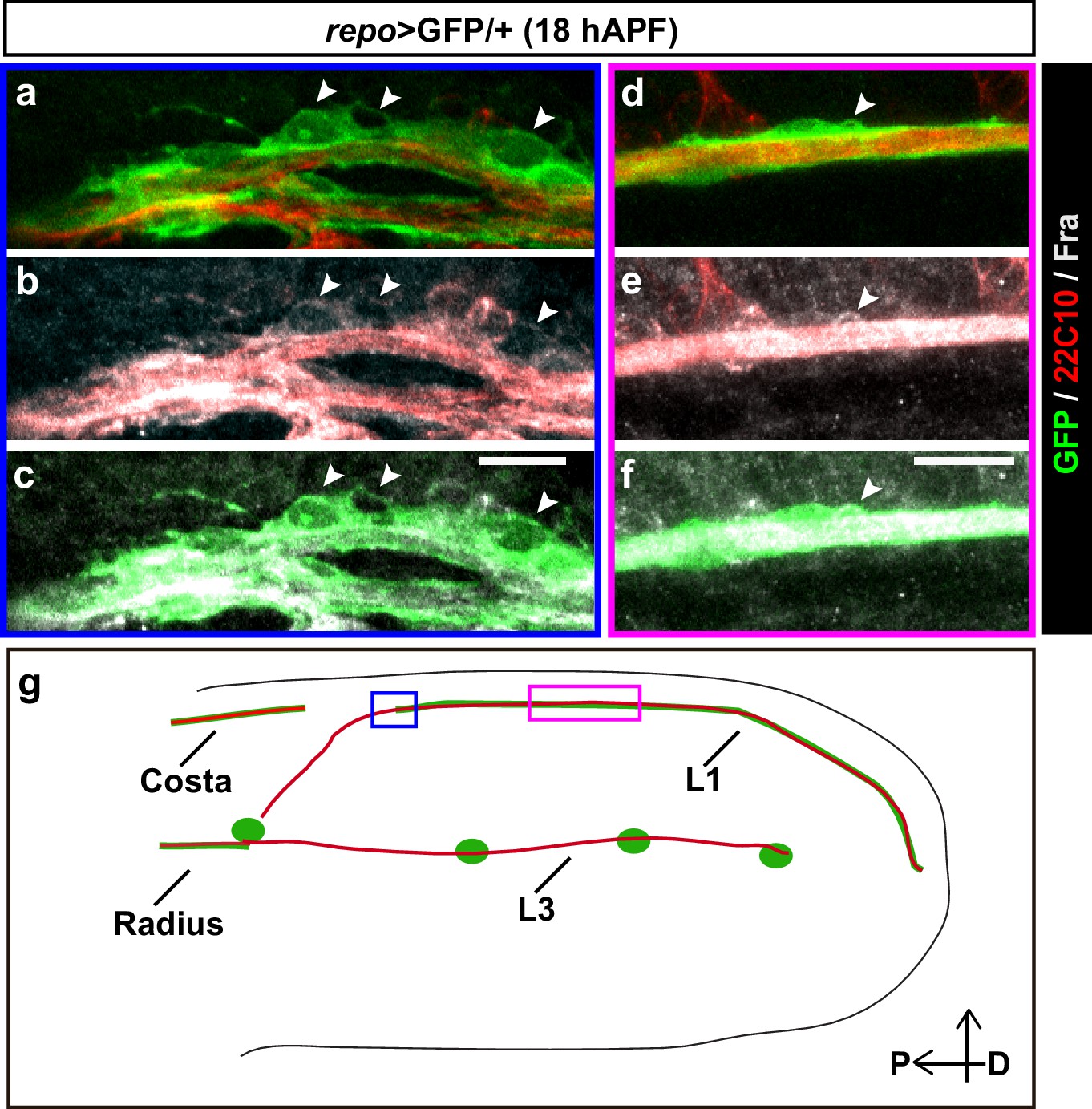
Expression profile of Fra.
(a–f) 18 hAPF repo>GFP/+ wing, immunolabeled with anti-22c10 (neurons in red), anti-Fra (gray) and anti-GFP (glia in green) shows the presence of Fra in the glial soma (white arrowheads) at the front of migration (a-–c) and along the L1 nerve (d–f). Please note that (a–c) are comprised of a few sections rather than maximum confocal projections. (g) Schematic of a wing, the blue rectangle indicates the region shown in (a–c), the magenta one, the region shown in (d–f). Scale bars: (a–f), 10 μm.
Figure 2
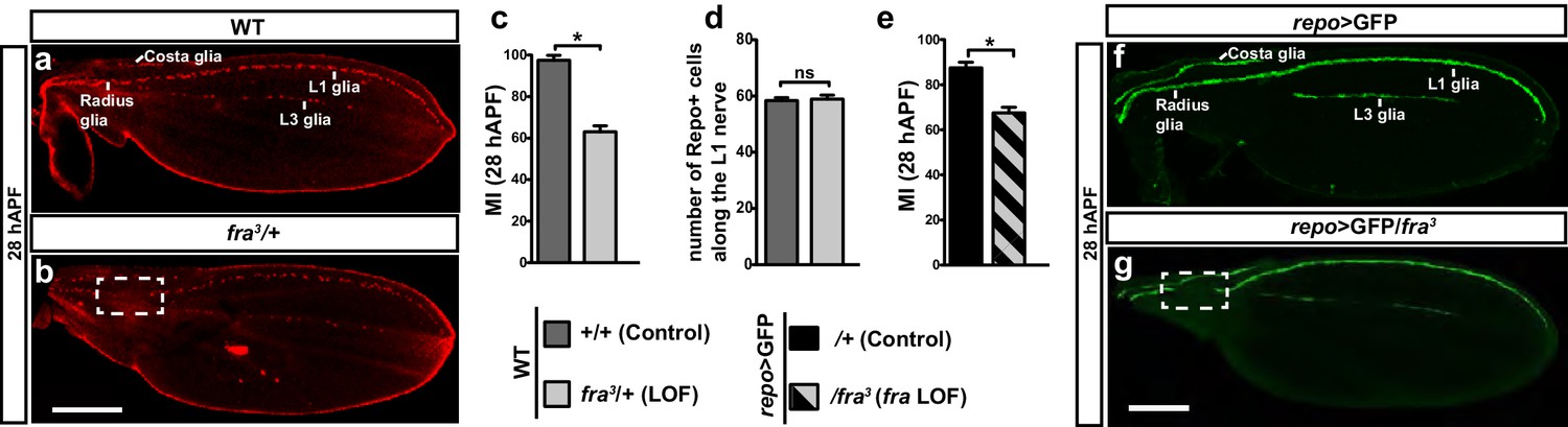
Role of Fra in wing glia.
(a, b) 28 hAPF wings labeled with anti-Repo (glial nuclei): (a) WT wing showing complete migration;(b) fra3/+ wing showing incomplete migration (dashed box). (c) Histogram representing the migratory index (MI) of the indicated genotypes, calculated using nuclear labeling (anti-Repo). The MI indicates the percentage of wings displaying complete migration (i.e. in which the glial chain reaches the proximally located glia on the Radius nerve) and was assessed at 28 hAPF unless otherwise specified. (d) Histogram representing the number of glial nuclei in the indicated genotypes. (e) Histogram representing the MI of the indicated genotypes. The MI was calculated using the membrane GFP transgenic line (UAS-mCD8-GFP). (f, g) 28 hAPF wings labeled with anti-GFP (glial processes): (f) repo>GFP wing showing complete migration; (g) repo>GFP/fra3/+ wing showing incomplete migration (dashed box). In this and in the following figures, stars indicate p values: ***p<0.0001; **p<0.001; *p<0.05. Bars indicate the s.e.m. In this and in the following graphs on fixed wings, n≥30. Scale bars: 80 μm.
-
Figure 2—source data 1
Migratory index and repo count of of fra3 wings in WT background.
This file contains underlying raw data for Figure 2.
- https://doi.org/10.7554/eLife.15983.005
Figure 3 with 2 supplements
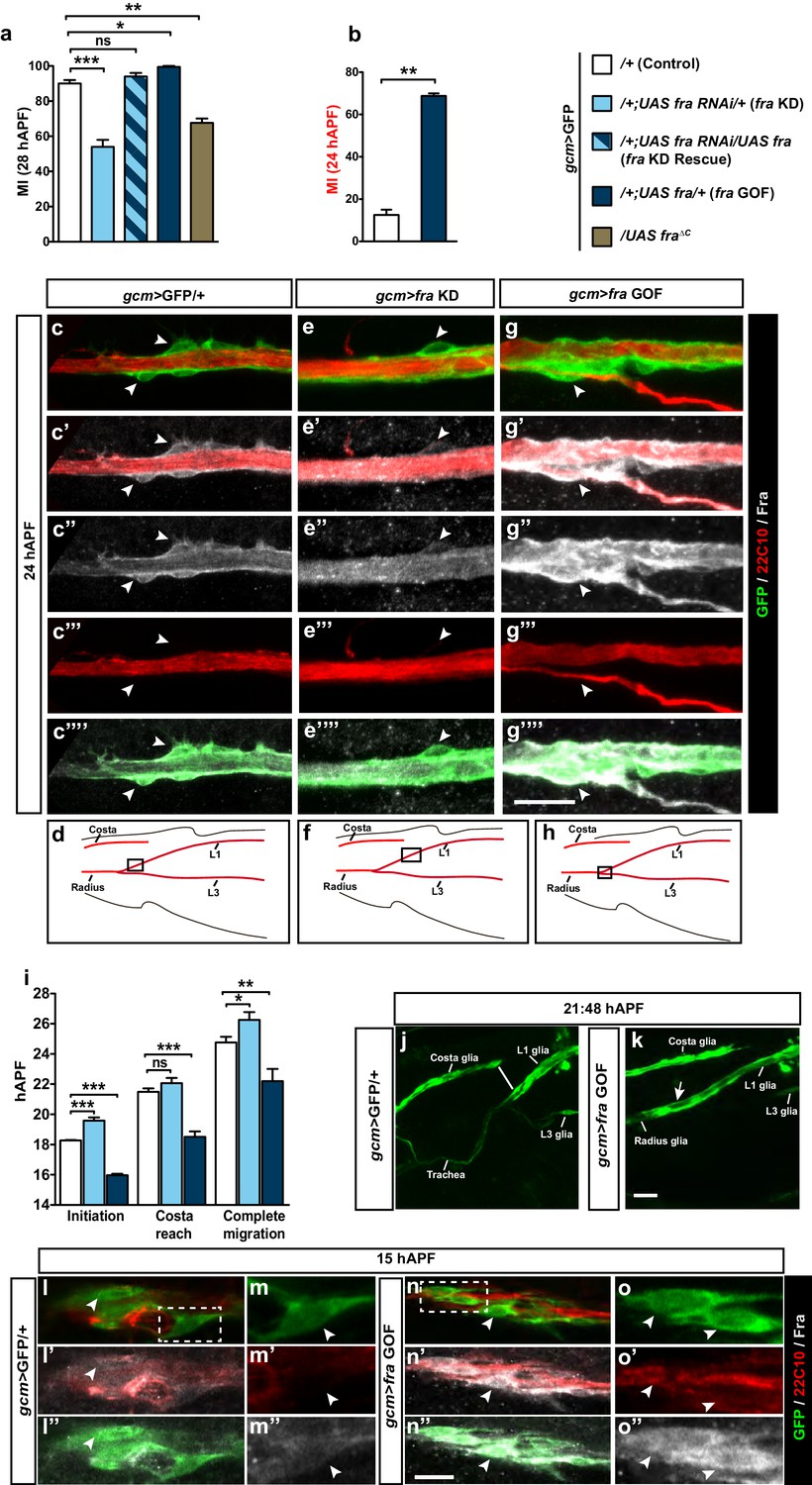
An instructive role of the chemoattractant receptor Fra in collective glia migration.
(a–b) Histogram representing the MI upon fra knock down (fra KD) or overexpression (fra GOF) using the gcm>GFP/+ line. In (b), the MI was calculated at 24 hAPF. The MI was calculated using the membrane GFP transgenic line. c–c’”’, e–e’”’ and g–g’”’ Expression profiles of Fra in gcm>GFP/+, gcm>fra KD and gcm>fra GOF animals at 24 hAPF. For the sake of consistency, in all genotypes, we show the glial cells that are at the front of the chain. Note the reduced protein levels in gcm>fra KD (e–e’”’) and enhanced levels in gcm>fra GOF animals (g–g’”’) as compared to those found in gcm>GFP/+ animals (c–c’”’). (d, f and h) Wing schematics, boxes indicate the regions shown in the above, high-magnification panels. (i) Graphical representation of the migratory behavior of gcm>GFP/+, gcm>fra KD and gcm>fra GOF wings during three highlighted phases: initiation, costa reach and complete migration (n=10). (j, k) Snapshots from a 21:48 hAPF time-lapse analysis of gcm>GFP/+ and gcm>fra GOF wings. This corresponds to the time by which most control L1 glia (gcm>GFP/+) have reached the level of the Costa (white line) (j), whereas L1 glia overexpressing Gcm (gcm>fra GOF) have already completed migration by that time (white arrow) (k). The two panels show representative samples. (l–o”) Expression profiles of Fra in gcm>GFP/+ and gcm>fra GOF animals at 15 hAPF. See the enhanced protein levels in gcm>fra GOF animals (n–o”) as compared to those found in gcm>GFP/+ animals (l–m”). The position of the high-magnification panels (m–m”) is highlighted by the dashed white rectangle in (l), whereas that of panels (o–o”) is highlighted in (n). Please note that (l–o”) are comprised of few a sections rather than maximum confocal projections. Scale bars: (c–g’”’), (j–o”), 10 μm.
-
Figure 3—source data 1
Migratory index and time-lapse analysis of fra conditional mutants in the gcm>GFP/+ background.
This file contains underlying raw data for Figure 3.
- https://doi.org/10.7554/eLife.15983.007
Figure 3—figure supplement 1
Migratory and neuronal defects in the frazzled mutation.
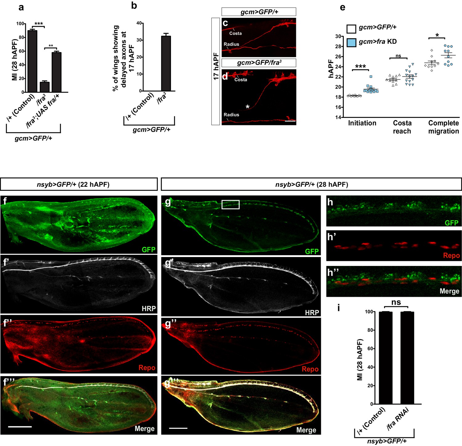
(a) Histogram representing the MI of the indicated genotypes, calculated using the membrane GFP transgenic line (UAS-mCD8-GFP). (b) Histogram showing the percentage of wings with axonal delay in gcm>GFP/+ (0%) and gcm/fra LOF (30%) 17 hAPF wings. (c) 17 hAPF control wing displaying normal axonal navigation. (d) Delayed axon bundle (asterisk) in a gcm/fra LOF wing at 17 hAPF. (e) Box plot showing the raw data, the mean and the standard errors for the three migratory phases in the indicated genotypes. Asterisks indicate the p values. (f–g’’’) Expression of nsyb>GFP at 22 and 28 hAPF: anti-HRP was used as a neuronal marker. (f–f’’’) are composite images. (h–h”) Blow up of the region indicated by white square in panel (g) shows lack of colocalization for the GFP (neuronal) and the Repo (nuclear) labeling. Note that the GFP is targeted to the Golgi in this transgenic line. (i) Histogram representing the MI of the indicated genotypes, calculated by nuclear labeling (anti-Repo). Scale bar: (c, d), 30 μm, (f, m), 80 μm.
-
Figure 3—figure supplement 1—source data 1
Summarizing the role of neurons in glia migration and the genetic interaction between gcm and fra in different transheterozygote combinations.
This file contains underlying source data for Figure 3—figure supplement 1 and 2.
- https://doi.org/10.7554/eLife.15983.009
Figure 3—figure supplement 2
Speed analysis and genetic interaction between gcm and fra in glia migration.
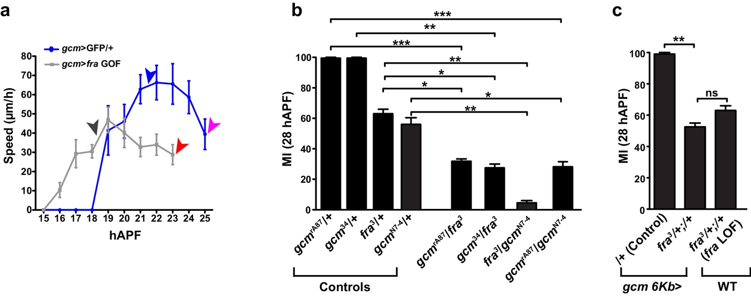
(a) Graph showing the speed of the most-proximal glial cell of the chain (μm/h, y-axis; hAPF, x-axis) in gcm>GFP/+ and in gcm>fra GOF glia. The distance covered by the front cell is measured by analyzing the position of the glial soma. Please note that migration initiation in gcm>fra GOF wings takes place earlier than in gcm>GFP/+ wings. Reaching the level of the costa (black vs. blue arrowhead) and completion of migration (red vs. pink arrowhead) also occur earlier in the Gcm-overexpressing wings than in the control wings. (b) Histogram showing the migratory index of mutants of the indicated genotypes, calculated by nuclear labeling (anti-Repo). (c) Histogram representing the MI of the indicated genotypes, calculated by nuclear labeling. This figure relates to both Figure 3 and Figure 4.
Figure 4
Gcm affects collective glia migration in a dose-dependent manner.
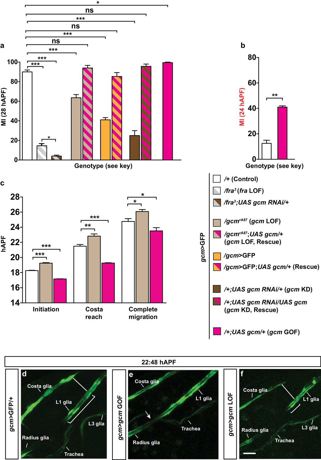
(a) MI in fra mutants, gcm LOF and rescues of the indicated genotypes: gcm>GFP/+, gcm/fra LOF, gcm>gcm LOF, gcm>gcm KD and gcm>gcm GOF wings. (b) MI calculated at 24 hAPF in gcm>gcm GOF wings. The MI was calculated using the membrane GFP transgenic line. (c) Graphical representation of the migratory behavior of gcm>GFP/+, gcm>gcm LOF and gcm>gcm GOF wings at three migratory phases. (d–f) Snapshots of a 22:48 hAPF time-lapse analysis on gcm>GFP/+, gcm>gcm GOF and gcm>gcm LOF wings. (d) 22:48 hAPF corresponds to the time at which L1 glia have surpassed the level of the Costa (white line) in the control gcm>GFP/+ wing, which is why this time point was chosen to compare the position of L1 glia in the different genetic backgrounds. By this time, (e) glia migration is already complete in gcm>gcm GOF wing (white arrow), while in (f) gcm>gcm LOF wing, L1 glia are still at the level of Costa (white line). Scale bar: (e–g), 10 μm.
-
Figure 4—source data 1
Summary of the role of gcm in glia migration.
This file contains underlying raw data for Figure 4.
- https://doi.org/10.7554/eLife.15983.012
Figure 5 with 1 supplement
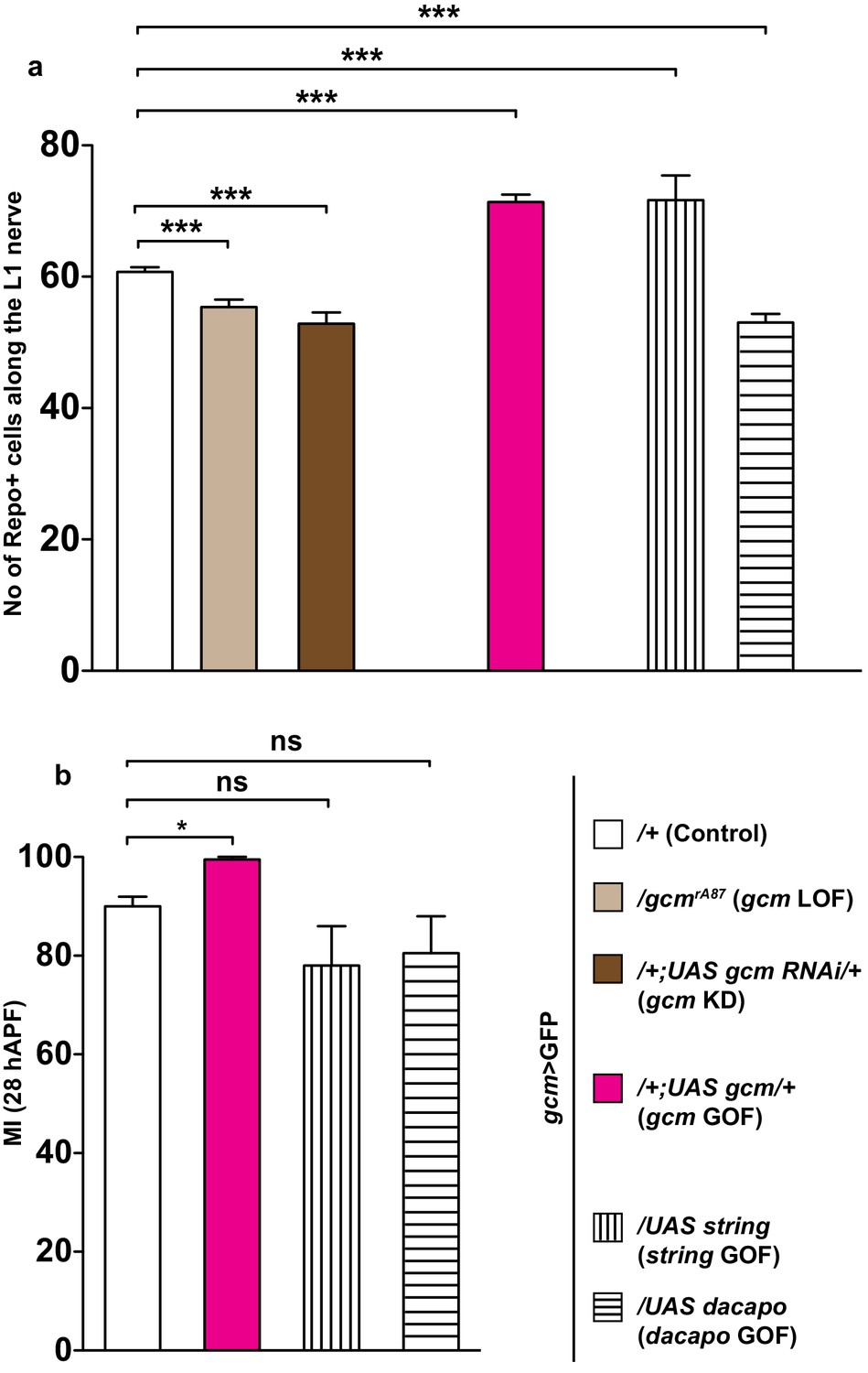
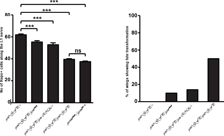
The effects of Gcm on collective glia migration are independent of the number of Repo-positive nuclei.
(a) Bar chart showing the numbers of L1 glial nuclei in the various genotypes. (b) MI in the various genotypes, calculated using the membrane GFP transgenic line.
-
Figure 5—source data 1
Effects of gcm on glia migration are independent of any change in the number of repo+ cells.
This file contains underlying raw data for Figure 5.
- https://doi.org/10.7554/eLife.15983.014
Figure 5—figure supplement 1
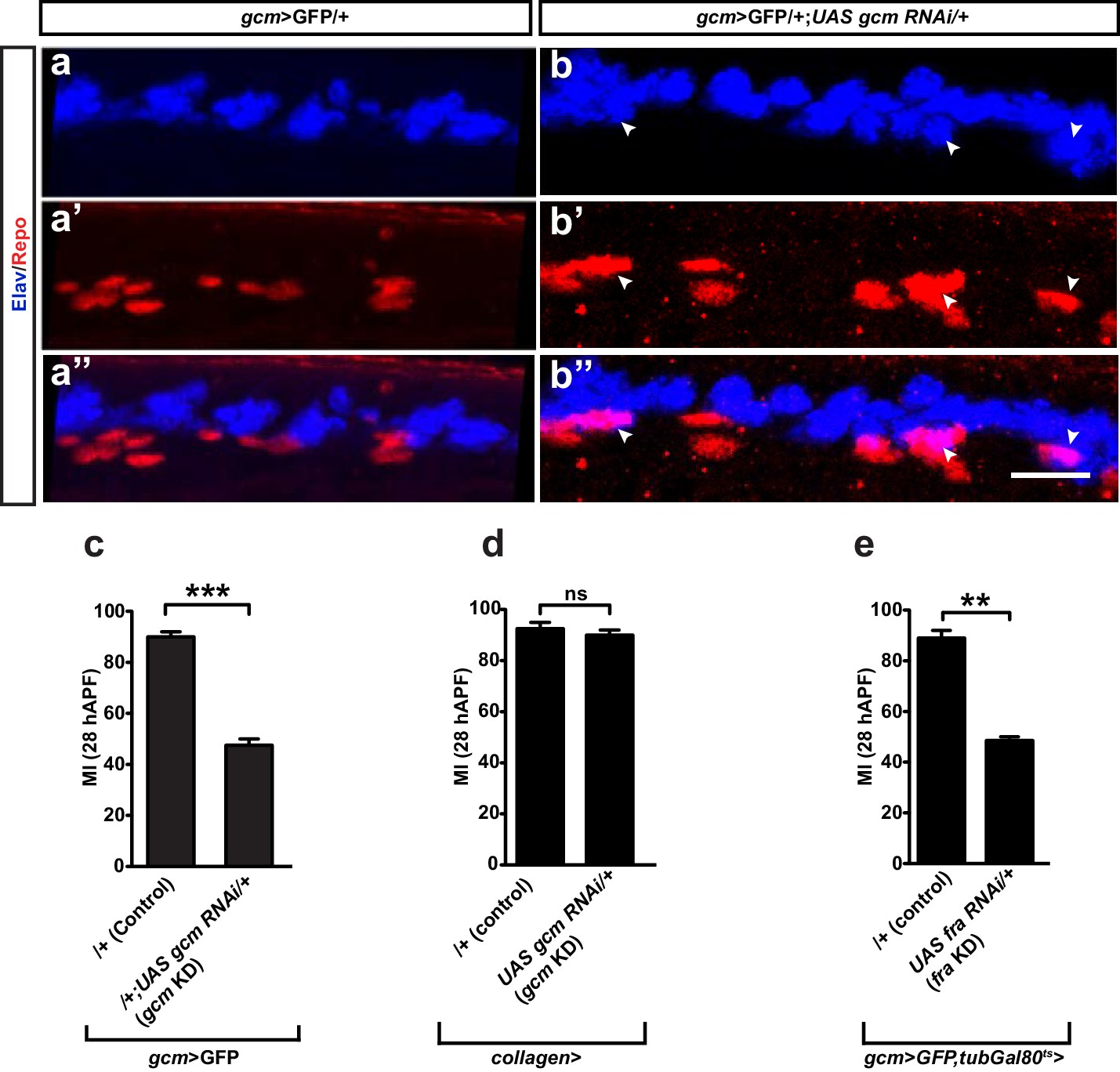
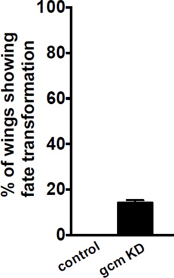
Fate conversion and Gcm expression in blood cells do not explain the gcm migratory phenotype.
(a–a”) gcm>GFP/+ and (b–b”) gcm>GFP/+;UAS-gcm-RNAi/+ 17 hAPF wings immunolabeled with anti-Elav (neuronal nuclei in blue) and anti-Repo (glial nuclei in red). Note the glial cells converted into neurons (white arrowheads) in (b”). (c) Histogram showing the MI of the gcm KD wings containing a wild-type number of glial cells. (d, e) Histogram showing the MI of the indicated genotypes. Note that, for panel (e), a ubiquitously expressed temperature-sensitive Gal80 construct was used that represses Gal4 activity at 18°C. The animals for this experiment were kept at 18°C and shifted to 25°C as they reached the second larval instar. Scale bar: (a, b), 10 μm.
Figure 6 with 1 supplement
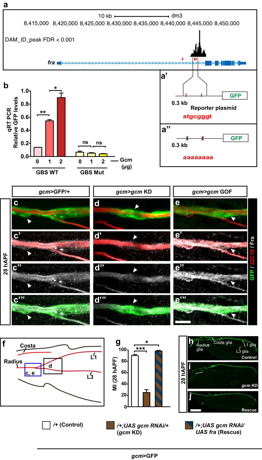
fra is a direct Gcm target.
(a) Schematic representation of the fra gene indicated in blue. Lines indicate the introns, thin regions indicate the untranslated sequences, thick regions indicate the coding exons, pale blue arrowheads indicate the direction of transcription. GBSs are indicated in red, the black histogram above shows the gcm DAM ID peak at the indicated genomic coordinates. (a’) Represents the two GBSs that were amplified and put in front of the GFP reporter to generate a fra WT plasmid. (a”) The two GBSs were mutated in order to generate a fra Mut plasmid. (b) qRT-PCR analysis of the GFP levels using a WT (red) or a mutant reporter plasmid (yellow) upon co-transfection with increasing doses of the Gcm expression vector (reported as μg) (n=3). (c–e”’) Immunolabeling of gcm>GFP/+, gcm>gcm KD and gcm>gcm GOF wings at 28 hAPF using anti-22c10 (red), anti-Fra (gray) and anti-GFP (green). Note the reduced Fra levels in the gcm>gcm KD and the increased levels in the gcm>gcm GOF wings as compared to those in the gcm>GFP/+ wings (arrows). (f) Wing schematics: the blue rectangle indicates the region shown in (c–c”’) and (e–e”’), the black one, the region shown in (d–d”’) (g) MI of the indicated genotypes calculated using the membrane GFP transgenic line. (h–j) 28 hAPF wings from the indicated genotypes: control (gcm>GFP/+), gcm>gcm KD and rescue (gcm>gcm KD/fra GOF). (h) gcm>GFP/+ wing shows complete migration. (i) gcm>gcm KD wing shows incomplete migration (white bracket). Note that this is a composite image. (j) gcm>gcm KD/fra GOF wing showing complete migration. Scale bar: (c–e”), 10 μm; (h, j), 80 μm.
Figure 6—figure supplement 1
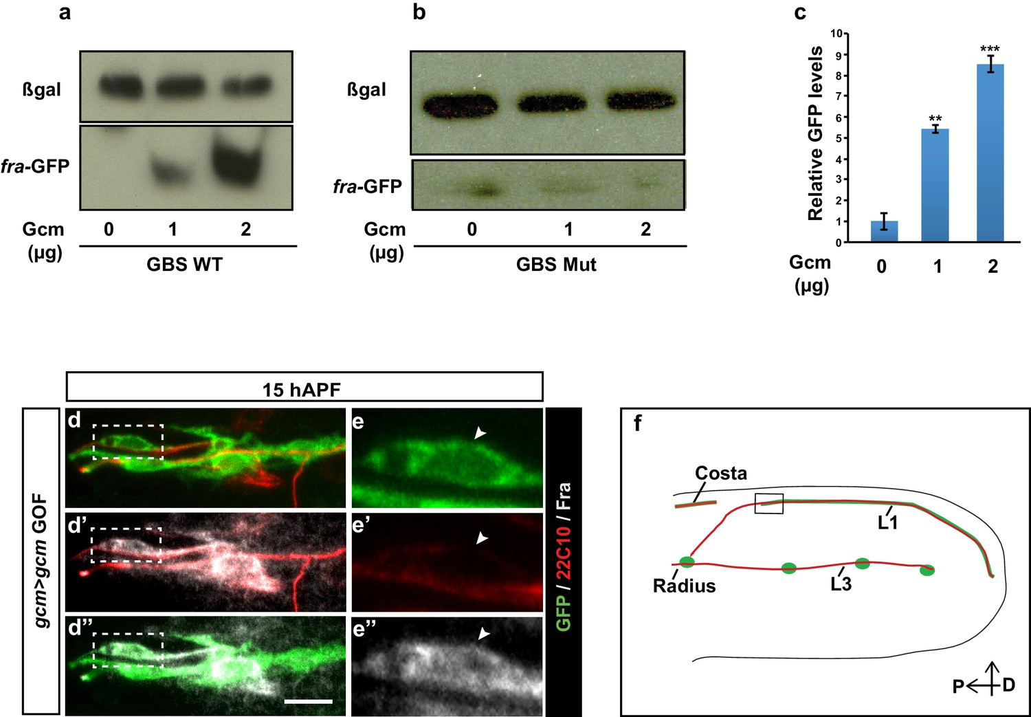
Assays confirming fra as a direct Gcm target.
(a) Western blot analysis on total protein extracts of transfected S2 cells showing the GFP levels from the fra-GFP reporter plasmid (representative Western Blot shows one out of a sample of three). GFP levels increase upon increasing the dose of Gcm. Anti-GFP was used for Fra detection (lower part) and anti-β-gal (top part) as a loading control. (b) Similar assay upon using a mutated fra-GFP plasmid. This analysis confirms Fra as a direct target of Gcm. (c) Quantification of the Western blot shown in (a), the y-axis indicates the relative GFP levels, the x-axis indicates the amounts of Gcm expression vector in (μg) (n=3). (d–e”) Immunolabeling with anti-Fra in a gcm>gcm GOF 15 hAPF wing. The position of the high-magnification panels (e–e”) is highlighted by the dashed white rectangles in (d–d”). Protein levels are enhanced in panels (d–e”) as compared to those in (Figure 3m–n”). (f) Schematic of a wing displaying the region shown in (d–d”). Scale bar: 10 μm.
Figure 7 with 2 supplements
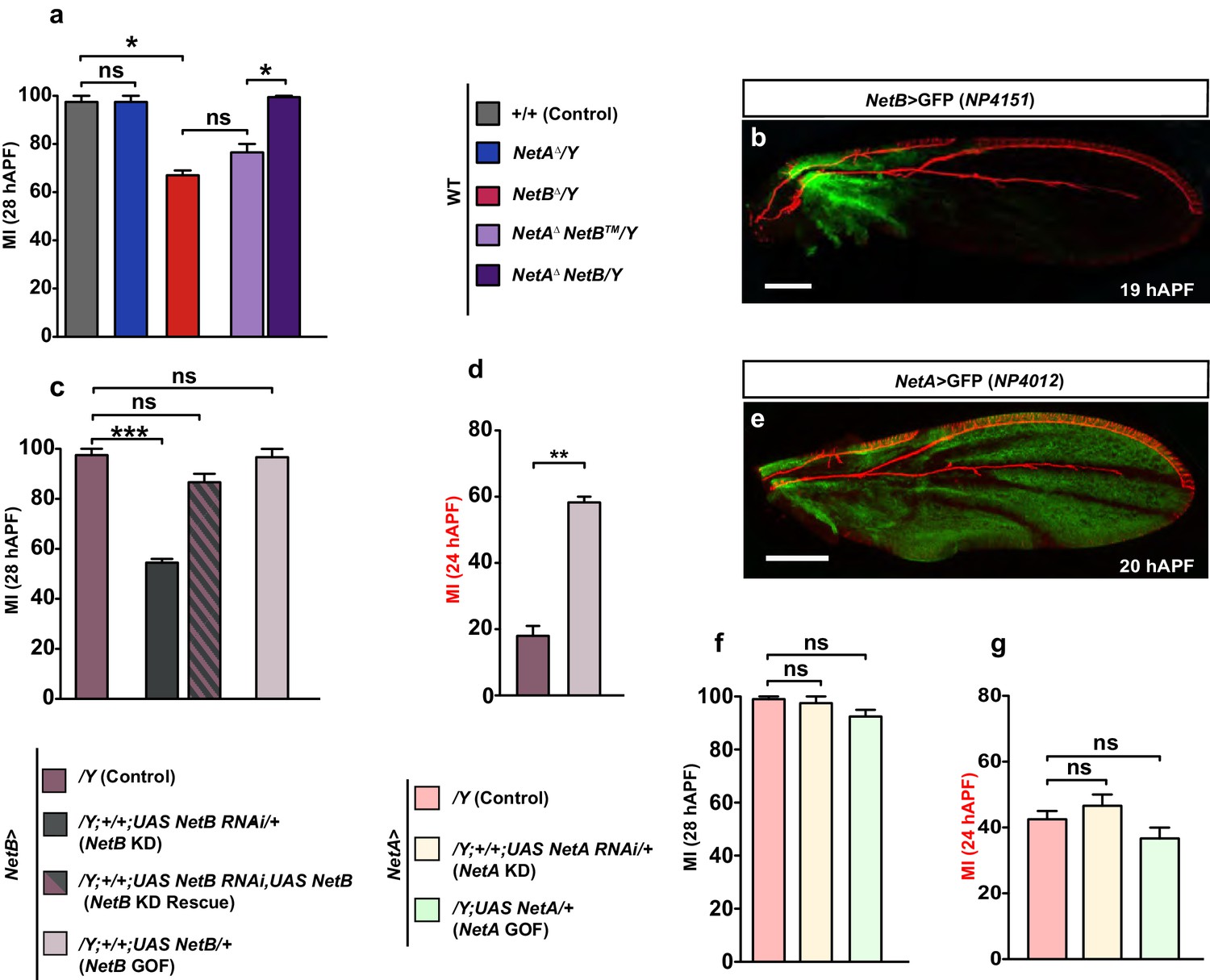
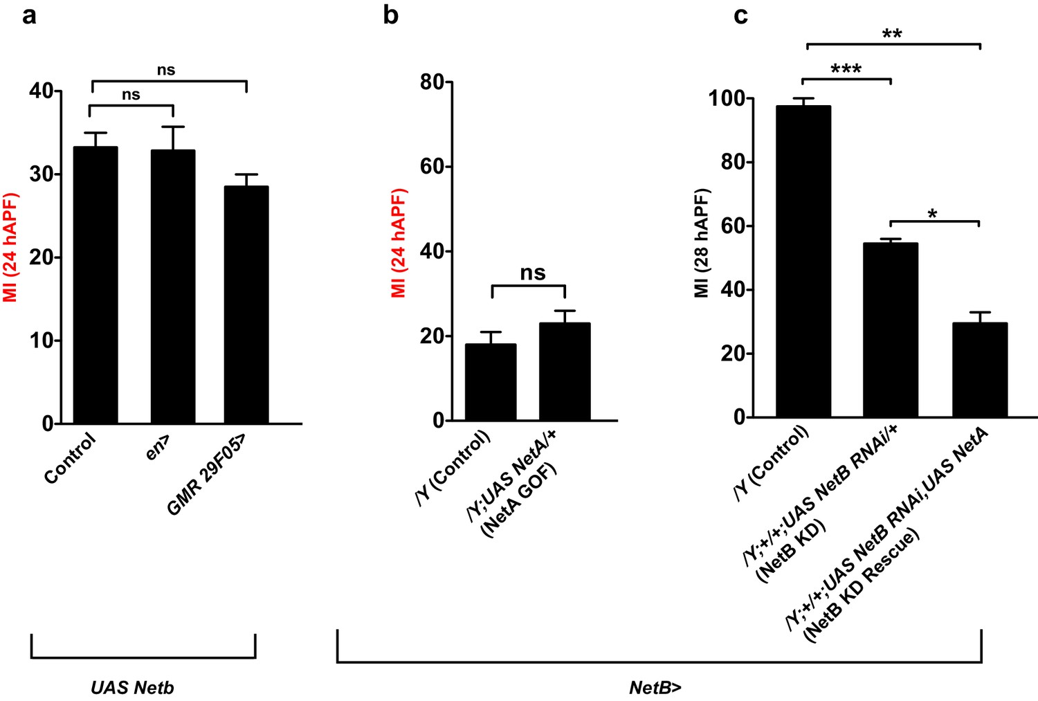
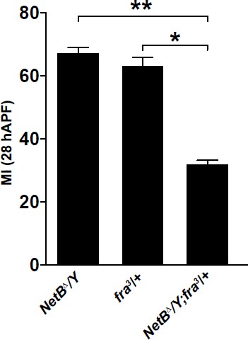
NetB serves as a chemoattractant in collective glia migration.
(a) MI of the indicated genotypes. Histogram shows the MIs quantified for WT, for NetAΔ or NetBΔ single mutant wings and for NetAΔNetBTM or NetAΔNetBmyc wings. (b) NP4151-Gal4 driven GFP expression of NetB in a 19 hAPF wing. Proximal NetB expression as revealed by the GFP labeling (green). Anti-22C10 is in red. (c, d) Histograms representing the MI of the indicated genotypes. (e) NP4012-Gal4 driven GFP expression of NetA in a 20 hAPF wing. NetA is expressed in the wing epithelium as revealed by the profile of GFP (green). Anti-22C10 is in red. (f, g) Histograms representing the MI of the indicated genotypes. For this figure the MI was calculated by nuclear labeling. Scale bars: (b, e), 80 μm.
-
Figure 7—source data 1
Summary of the role of Netrins in glia migration.
This file contains underlying raw data for Figure 7.
- https://doi.org/10.7554/eLife.15983.019
Figure 7—figure supplement 1
Role of Netrins in collective glia migration.
(a–c) Graphs representing the MI of the indicated genotypes, calculated by nuclear labeling.
Figure 7—figure supplement 2
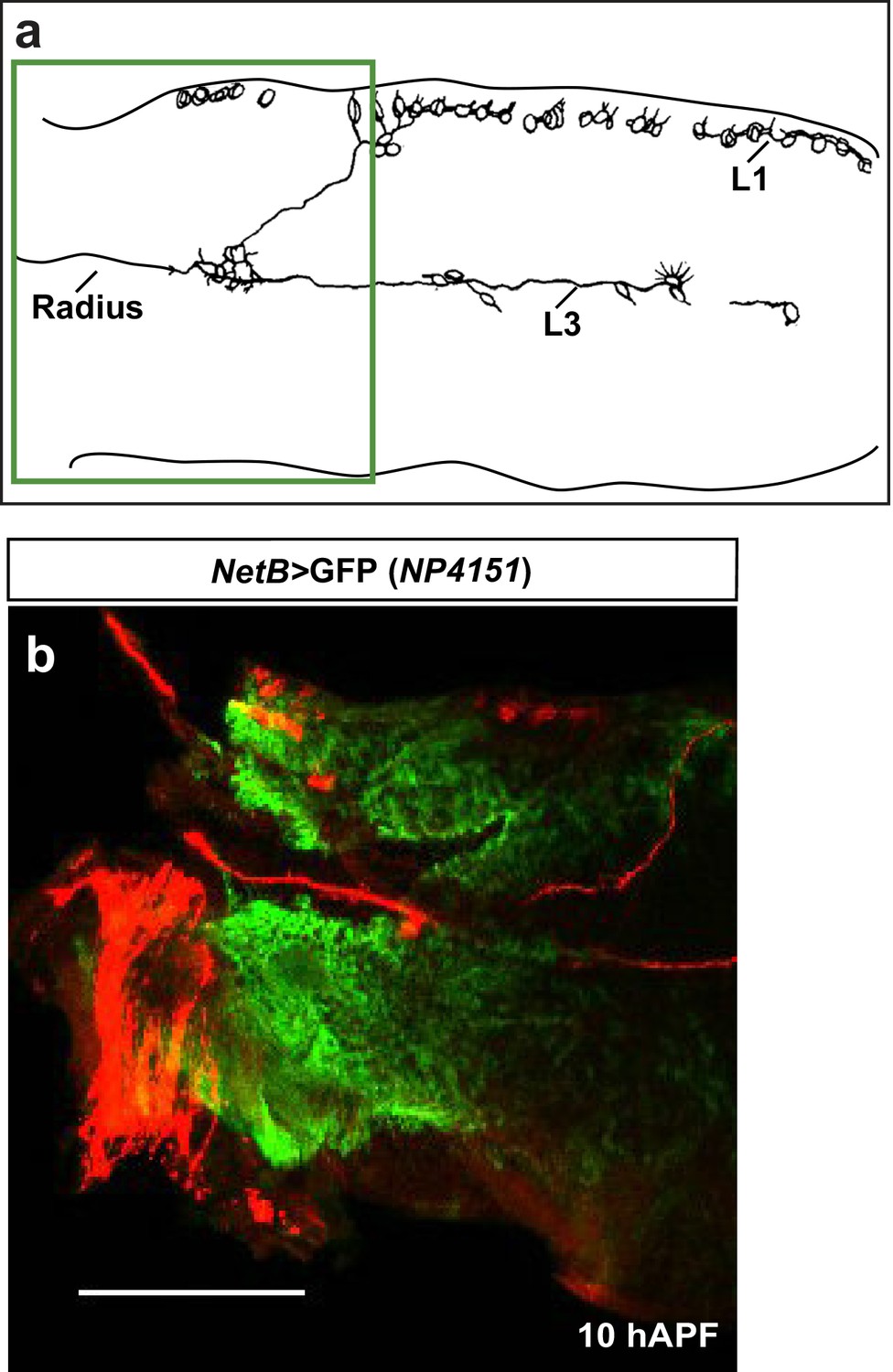
Early expression of NetB.
(a) Schematic of axonal bundles in a 10 hAPF wing, the green rectangle indicates the region shown in (b). (b) NP4151-Gal4-driven GFP expression of NetB in a 10 hAPF wing. Proximal NetB expression as revealed by the GFP labeling (green). Anti-22C10 is in red.
Figure 8 with 1 supplement
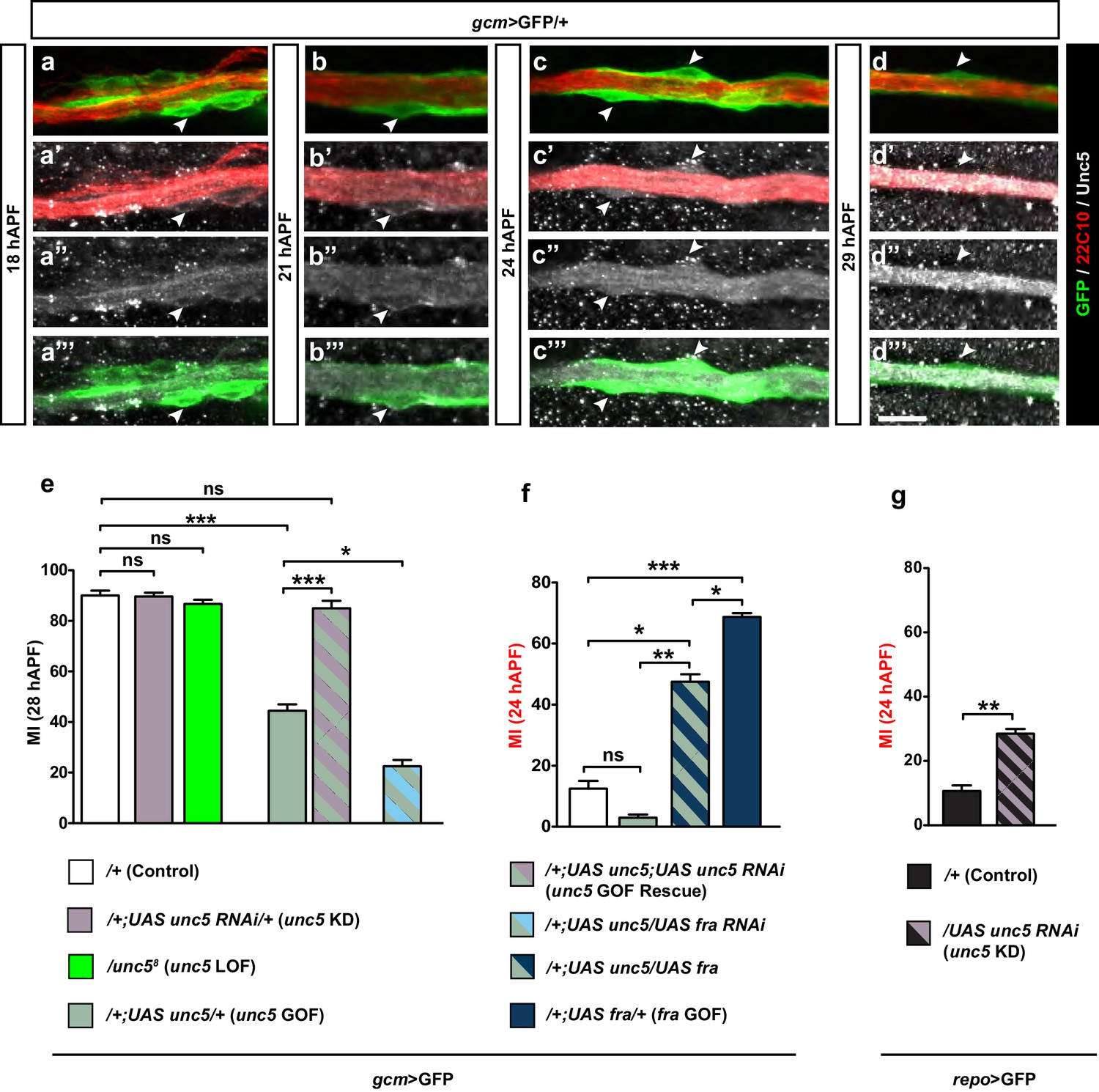
Unc5 may act as a repellant in glia migration.
(a–d”’) Wing immunolabeled with anti-22c10 (red), anti-Unc5 (gray) and anti-GFP (green) in the transgenic line gcm>GFP/+ at different migratory stages. Unc5 starts being expressed in glia and neurons at around 18 hAPF and fades away by 29 hAPF. Arrowheads show glia that express Unc5 at weak levels (a–c’’’) or that do not express Unc5 (d–d’’’). Note that (a–d”) are comprised of a few sections rather than maximum confocal projections. (e–g) Histograms representing the MI of the indicated genotypes, which in this figure was calculated using the membrane GFP transgenic line. Scale bars: (a–d”), 10 μm.
-
Figure 8—source data 1
Summary of role of unc5 in glia migration.
This file contains underlying raw data for Figure 8.
- https://doi.org/10.7554/eLife.15983.023
Figure 8—figure supplement 1
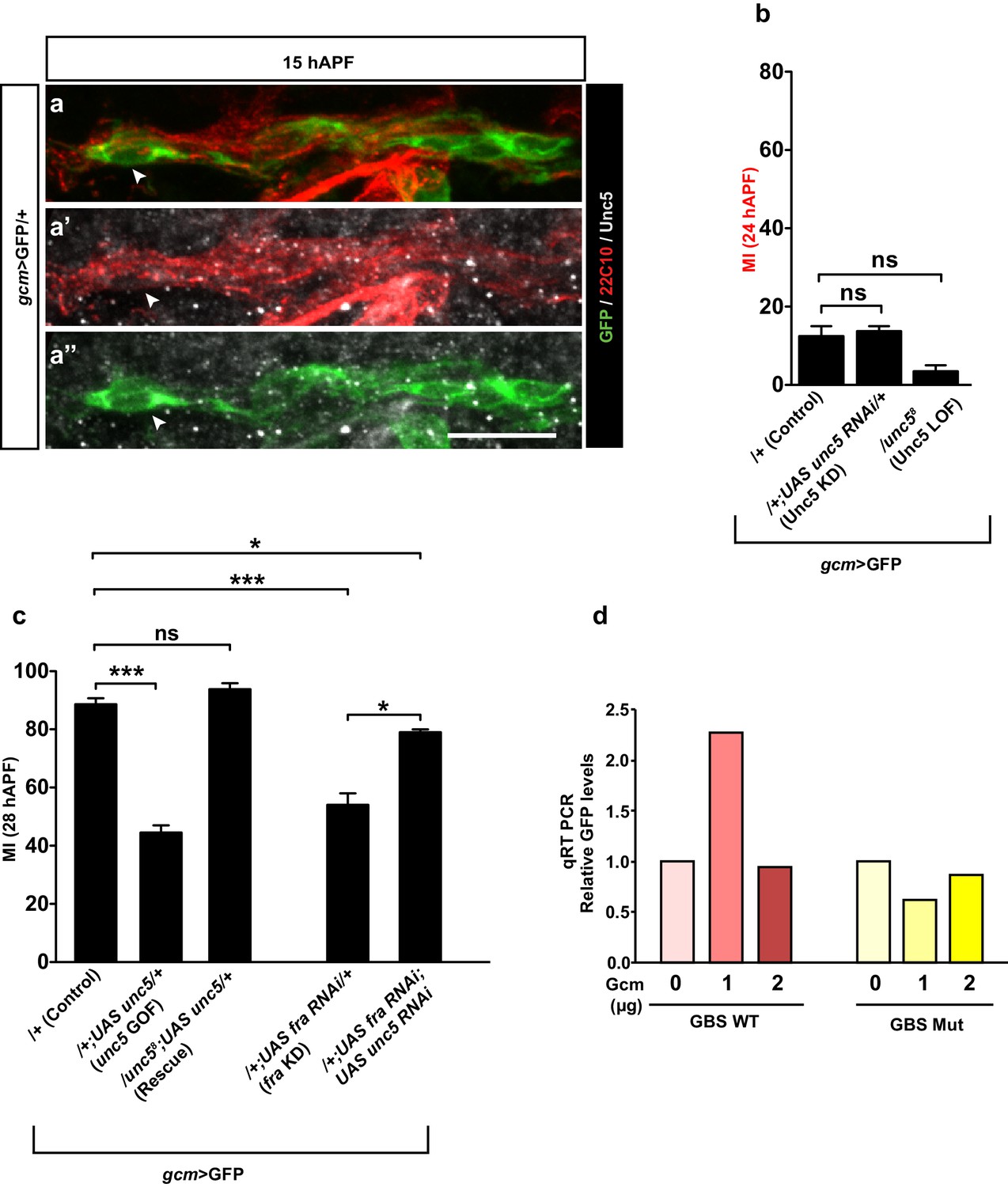
Unc5 in collective glia migration.
(a–a”) gcm>GFP/+ wing immunolabeled at 15 hAPF shows that the Unc5 protein cannot be detected at this stage. Note that (a–a”) are comprised of a few sections rather than maximum confocal projections. Region and scale bar as in Figure 6—figure supplement 1d–d’’. (b, c) Histograms represent the MI of the indicated genotypes, calculated by using the membrane GFP transgenic line. (d) qRT PCR analysis of the GFP levels using a WT unc5 (red) or a mutant unc5 reporter plasmid (yellow) upon co-transfection with increasing doses of the Gcm expression vector (reported as μg).
Figure 9 with 1 supplement
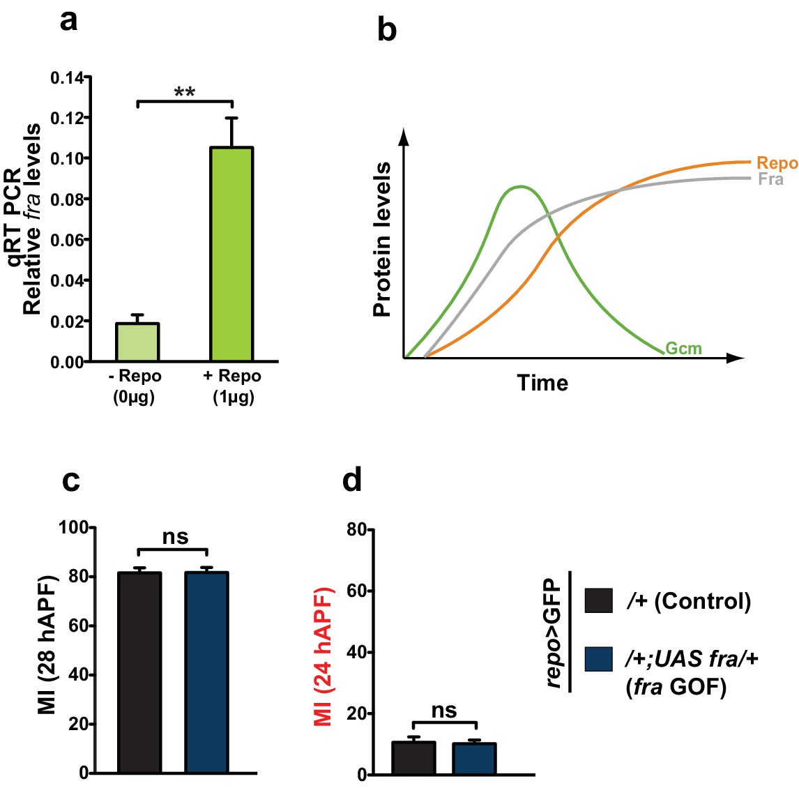
Repo regulates Fra at late stages.
(a) Histogram showing the endogenous expression of fra upon S2 cell transfection with a Repo expression vector. The y-axis represents the relative expression levels in cells transfected with Repo compared to that observed in cells not transfected with the Repo expression vector (n=3). (b) Schematic summarizing the regulatory network. (c, d) Graphs representing the MI found at early and late stages in fra GOF animals crossed with the repo-Gal4 line. In this figure, the MI was calculated using the membrane GFP transgenic line.
-
Figure 9—source data 1
Summary of role of repo in glia migration.
This file contains underlying raw data for Figure 9.
- https://doi.org/10.7554/eLife.15983.026
Figure 9—figure supplement 1
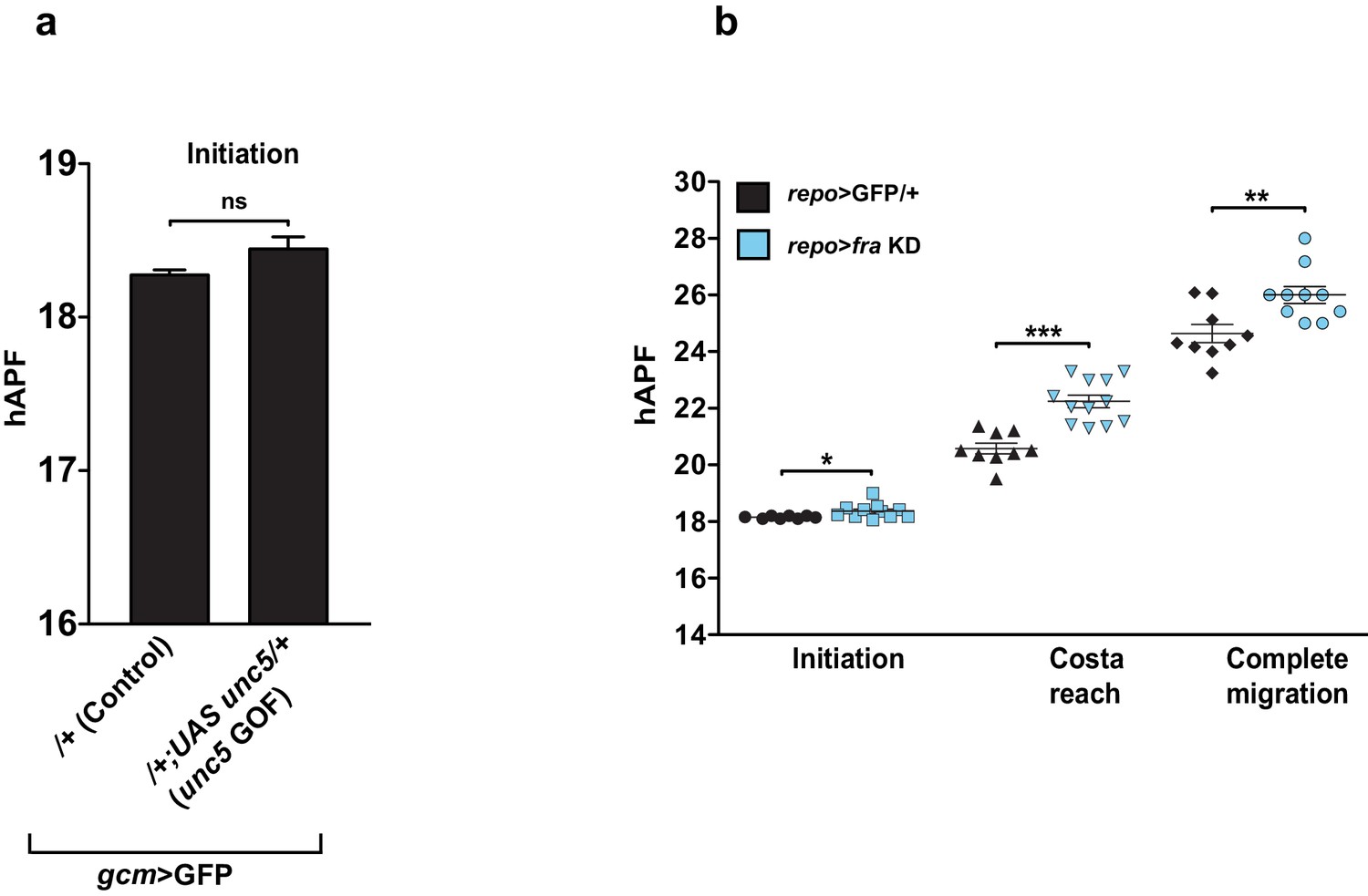
In vivo analysis of Unc5 GOF wings and fra KD wings using a late driver.
(a) Graphical representation of the migratory behavior of gcm>GFP/+ and gcm>unc5 GOF wings at the Initiation phase (n=9). (b) Box plot showing the raw data, the mean and the standard errors for the three migratory phases in repo>GFP/+ and repo>fra KD wings. Stars indicate the p values. This figure relates to both Figure 8 and Figure 9.
Author response image 1
Author response image 2
25 hAPF immunolabeled wing of the elav-Gal4,UASmCD8GFP transgenic line (anti-GFP in green and anti-Repo in red).
Note the presence of the mCD8GFP in the axons, in the glia (Repo-positive cells in red, arrows) and in the epithelium (asterisk).
Author response image 3

Author response image 4
Author response image 5
Download links
A two-part list of links to download the article, or parts of the article, in various formats.
Downloads (link to download the article as PDF)
Open citations (links to open the citations from this article in various online reference manager services)
Cite this article (links to download the citations from this article in formats compatible with various reference manager tools)
The Glide/Gcm fate determinant controls initiation of collective cell migration by regulating Frazzled
eLife 5:e15983.
https://doi.org/10.7554/eLife.15983


