Multi-neuron intracellular recording in vivo via interacting autopatching robots
- Massachusetts Institute of Technology, United States
- Georgia Institute of Technology, United States
- Massachusetts General Hospital, United States
- Boston University, United States
Figures
Figure 1 with 2 supplements
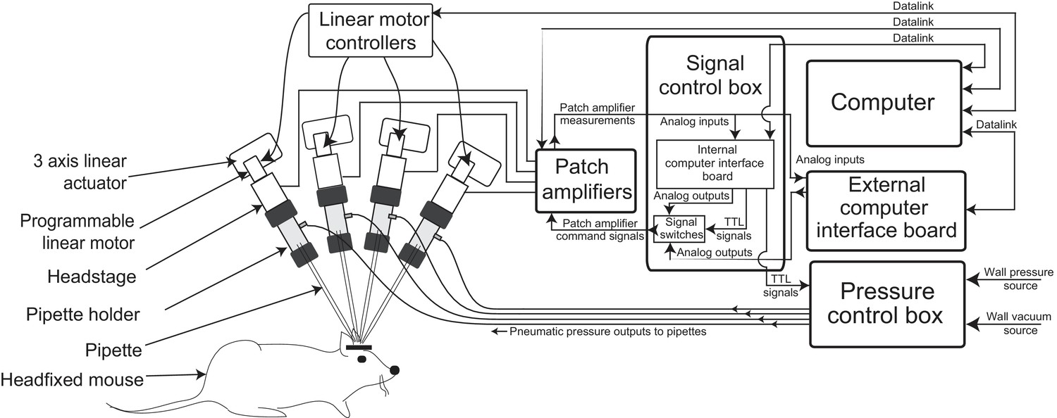
Multipatching robot: hardware architecture.
(a) Schematic of multipatching robot used for obtaining whole-cell patch recordings from multiple neurons simultaneously in vivo. The system consists of four robotic arms arranged radially and associated signal and pressure control hardware. The pipette, pipette holder and the amplifier headstage are mounted to the robotic arms (see also Figure 2). Each headstage is connected to a patch amplifier, which routes signals to a computer via two computer interface boards. A computer interface board, located within the main signal control box, also serves to control the pressure regulation device that can apply pressures ranging from −350 to 1000 mBar independently to each patch pipette (see also Figure 1—figure supplements 1 and 2).
Figure 1—figure supplement 1
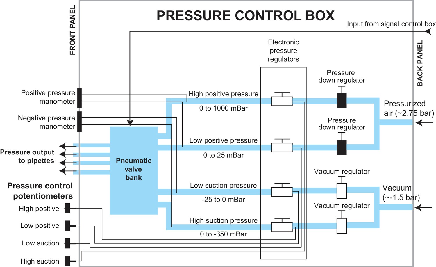
Schematic of the pressure control box.
The pressure control box was designed to independently apply four possible pressures to each of the four pipettes. The pressure control box received compressed air at approximately 2.75 bar and vacuum pressure at approximately −1.5 bar. It regulated these input pressures to the required pressures using a series of manual and electronically controlled pressure regulators that fed into a pneumatic valve bank. this pneumatic valve bank switched the pipettes between pressure states during the multipatcher operation.
Figure 1—figure supplement 2
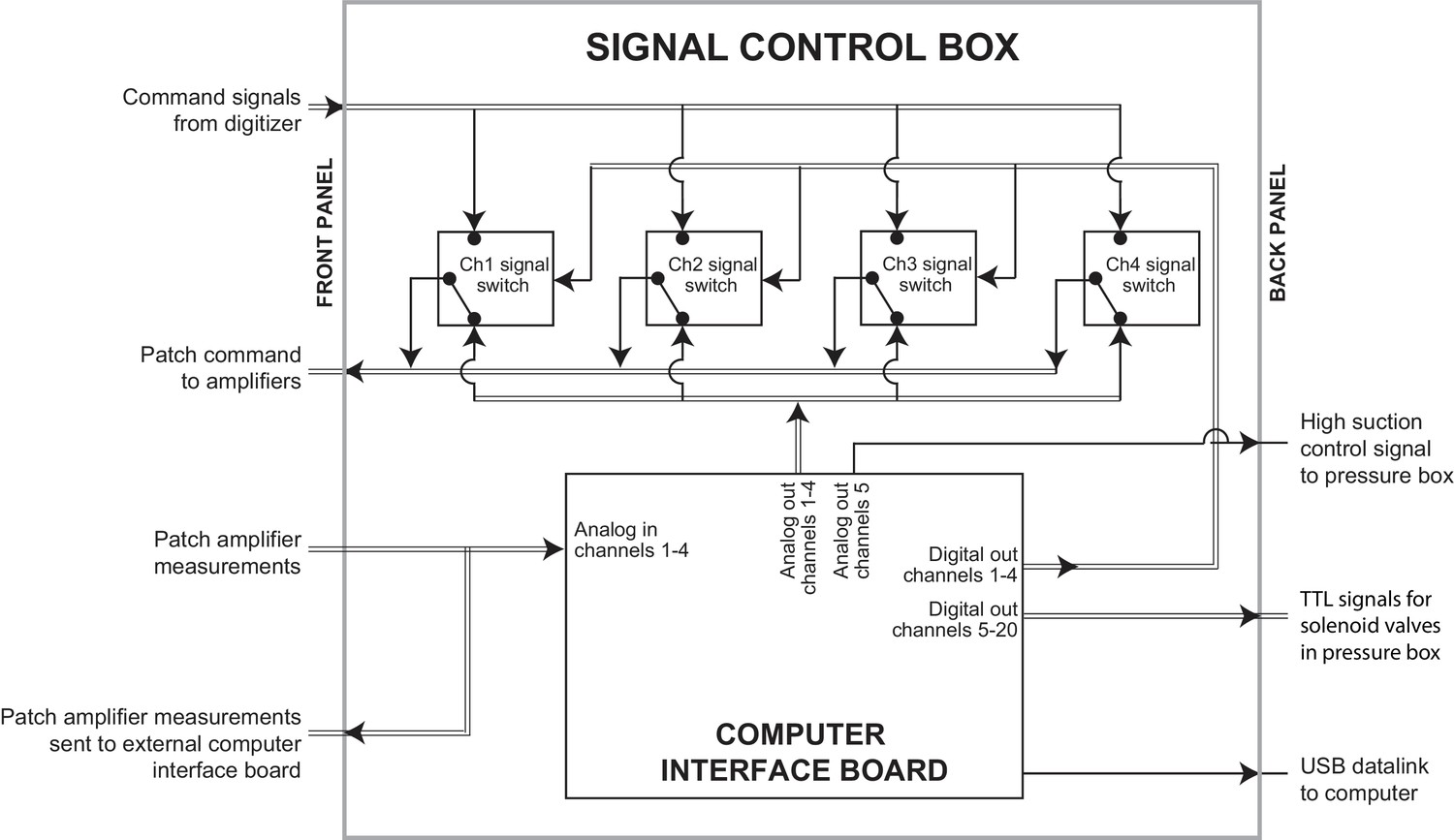
Schematic of the signal control box.
Within the signal control box, an interface board was connected to the computer executing the multipatcher algorithm via a Universal Serial Bus (USB) datalink. Analog output channels on the interface board were used to send command voltage signals to the amplifiers. Analog input channels were used to read measurements taken from the patch amplifiers. BNC relays were controlled using digital Transistor-Transistor-Logic (TTL) signals to switch the command signal being sent to the patch amplifier between the analog outputs on the computer interface board and the analog outputs on the digitizer. TTL signals, and one analog voltage signal from the interface board were also sent to the pressure control box.
Figure 2

Computer aided design (CAD) rendering and photographs of the multipatcher.
(a) CAD rendering illustrating details of a single robotic arm that allows 3-axis manual motorized and programmatic control of the pipette's axial position. The pipette is mounted on a pipette holder, which is in turn mounted on a bearing driven by a programmable linear motor. (b) Corresponding photograph showing a single robotic arm. Scale bar indicates 50 mm. (c) Top view rendering of the array of robotic arms illustrating relative arrangement. (d) Side view photograph of the array of robotic arms, with inset showing the arrangement of the pipette tips relative to the head plate affixed to the mouse, the head plate fixation base, and animal warming pad used in anesthetized experiments. Scale bars indicate 25 mm.
Figure 3 with 1 supplement
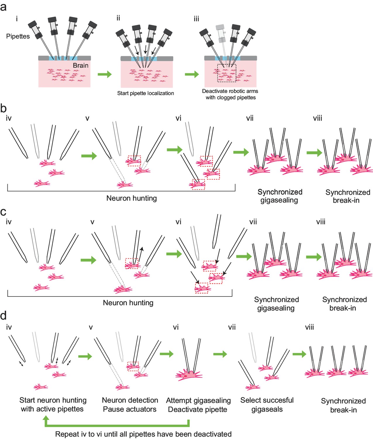
Development of the multipatcher algorithm.
(a) The initial steps of the multipatcher algorithm: (i) The experimenter manually positioned the pipettes in contact with the cortical surface. (ii) The robot automatically lowered all pipettes to the desired target region in the brain. (iii) Clogged pipettes were detected and deactivated (grayed out pipette). The pipettes that were still active continued seeking for neurons. The black box in iii denotes the region zoomed in in the next figure panels. (b) Schematic of the first development iteration: (iv) active pipettes continued hunting for neurons. (v) whenever a pipette encountered a neuron (red box) the corresponding motor was deactivated, while the rest continued seeking for neurons. (vi) in this example, all active pipettes have made contact with neurons (red boxes). (vii) gigasealing was attempted simultaneously in all pipettes, by releasing positive pressure, applying suction pressure and applying hyperpolarizing voltages synchronously. (viii) Breaking-in was then attempted synchronously in all cells with successful gigaseals. (c) Schematic of the second development iteration: (iv) active pipettes continued hunting for neurons, moving at steps of 2 m. (v) each time a pipette encountered a neuron, it was retracted back by 30 m (black arrow), and held in that position. (vi) once all pipettes had performed this step, all pipettes were simultaneously lowered down to the positions where they had previously encountered neurons (black arrows). (vii) synchronous gigasealing was attempted. (viii) synchronous break-in was attempted in all gigasealed neurons. (d) Third and final development iteration: (iv) The multipatcher moved the pipettes simultaneously at 2 m steps (black arrows). (v) when a pipette detected a neuron, all pipettes were halted. (vi) gigasealing was attempted on the single pipette that had detected a neuron. (vii) After the gigasealing procedure was completed, whether successful or not, the remaining pipettes resumed neuron hunting. Steps iv to vi were repeated until gigasealing had been attempted on all active pipettes. (vii) pipettes with resistance greater than 1 G were selected by the algorithm to continue to break-in stage. (viii) Break-in was performed simultaneously on all gigasealed neurons.
Figure 3—figure supplement 1
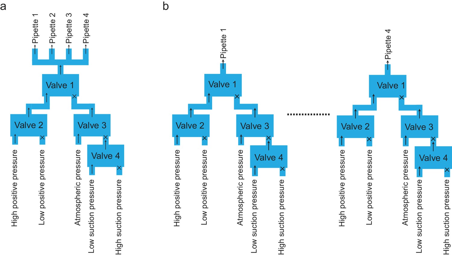
Schematics of valve bank’s configurations across the different iterations of the algorithm.
(a) Configuration of valve bank used for applying pressure states to the pipettes within the algorithm iterations shown in Figure 3a and b. With all pressure state switching events synchronized in all pipettes, a single valve bank was used to supply pressure in parallel to each pipettes. (b) The final algorithm (Figure 3c) required a valve bank dedicated to each pipette to account for asynchronous switching of the pressures states.
Figure 4 with 1 supplement
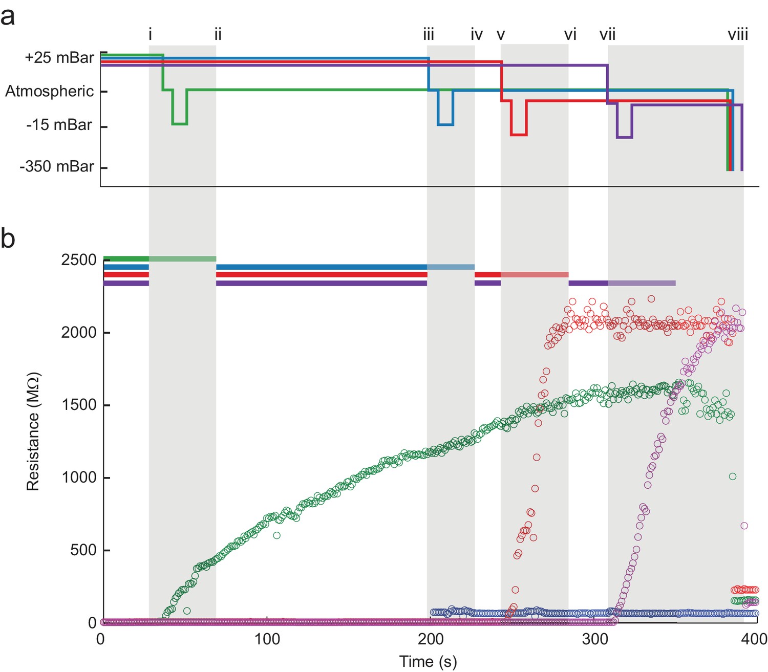
The multipatcher robot in operation.
(a) Time series of the pressures in each of the four valves during the multipatcher operation. The valve pressure settings, each corresponding to a pipette, are color coded blue, green, red and purple. The roman numerals and gray areas denote different steps of the algorithm operation, as shown in Figure 3d. (b) Time series of resistance measurements in a representative multipatching trial. Colors and roman numerals are coded as in (a). The horizontal bars on top indicate the epochs of the algorithm when motors are active and moving, and the grayed out sections indicate epochs when gigasealing was attempted in a pipette. The vertical gray bars indicate epochs in which all pipettes remained stationary. Key events are flagged by roman numerals. Between i and ii gigasealing was attempted in the pipette color-coded green; between iii and iv, gigasealing was attempted in the pipette color coded blue. In this gigasealing attempt, the experimenter utilized a manual override option to prematurely terminate the gigasealing process after observing less than 100 M increase in pipette resistance after 35 s, typically indicative of an unsuccessful gigasealing attempt. Gigasealing was attempted similarly with pipettes color coded red and magenta between time points v to vi and vii to viii respectively. Break-in was attempted in all pipettes that had successfully obtained gigaseals at step ix and obtained whole-cell configurations in all three pipettes.
-
Figure 4—source data 1
Time series of resistance measurements.
- https://doi.org/10.7554/eLife.24656.010
Figure 4—figure supplement 1
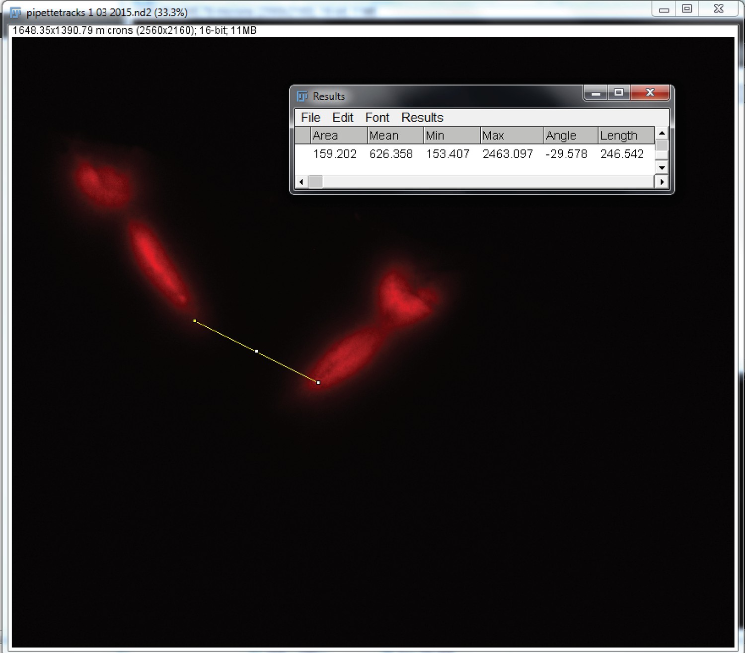
Pipette tracks in the somatosensory cortex after a complete experiment.
Confocal image of somatosensory cortex showing the tracks left by two pipettes painted with DiI. The measurement scale show that the pipettes are at about 250 m from each other.
Figure 5

The multipatcher robot in operation.
(a) Representative voltage traces for two neurons patched simultaneously in the somatosensory cortex of awake (left) and anesthetized (right) head restrained mouse. (b) Representative voltage traces from three neurons patched simultaneously in the somatosensory cortex of an awake (left) and anesthetized (right) head-fixed mouse. (c) Initial series resistances of neurons recorded at various depths in the cortex plotted against the depths from the pia at which the recordings were obtained. (d) Holding currents required to hold various whole-cell patched neurons at −65 mV in voltage clamp mode plotted against the depth from the pia at which recordings were obtained.
-
Figure 5—source data 1
Raw traces of a double patch in S1 of an anesthetized mouse.
- https://doi.org/10.7554/eLife.24656.012
-
Figure 5—source data 2
Raw traces of a triple patch in S1 of an anesthetized mouse.
- https://doi.org/10.7554/eLife.24656.013
-
Figure 5—source data 3
Raw traces of a double patch in S1 of an awake mouse.
- https://doi.org/10.7554/eLife.24656.014
-
Figure 5—source data 4
Raw traces of a triple patch in S1 of an awake mouse.
- https://doi.org/10.7554/eLife.24656.015
-
Figure 5—source data 5
Depth, Series resistance, and holding current during whole-cell recordings in anesthetized S1.
- https://doi.org/10.7554/eLife.24656.016
-
Figure 5—source data 6
Depth, Series resistance, and holding current during whole-cell recordings in anesthetized V1.
- https://doi.org/10.7554/eLife.24656.017
-
Figure 5—source data 7
Depth, Series resistance, and holding current during whole-cell recordings in awake S1.
- https://doi.org/10.7554/eLife.24656.018
Figure 6
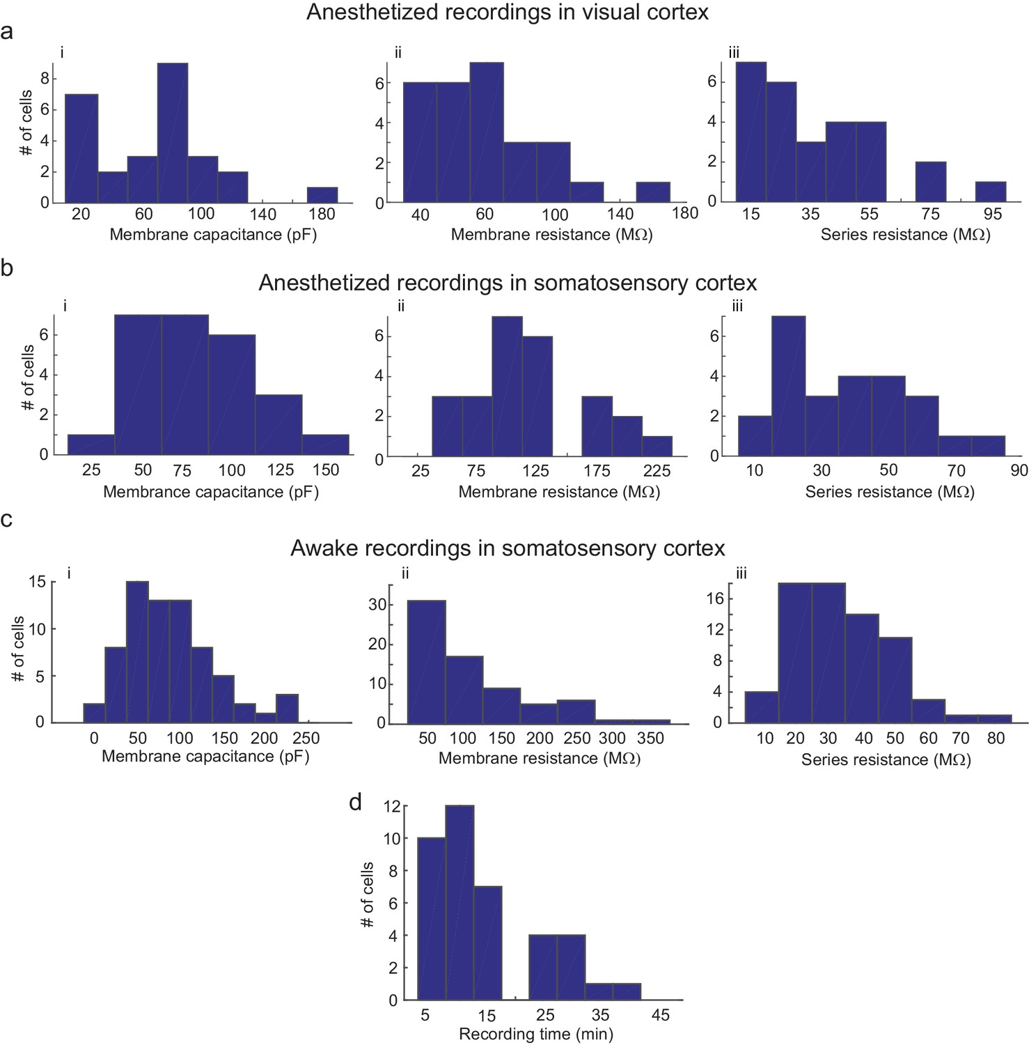
Parameters of cells recorded using the multipatcher robot.
(a) i-iii are histograms of cell membrane capacitance, cell membrane resistance and series resistance, respectively, from neurons recorded in the visual cortex under anesthesia (n = 27 neurons), (b) i-iii are histograms of cell membrane capacitance, cell membrane resistance and series resistance, respectively, from neurons recorded in the somatosensory cortex under anesthesia (n = 25 neurons, four mice), (c) i-iii are histograms of cell membrane capacitance, cell membrane resistance and initial series resistance, respectively, from neurons recorded in the somatosensory cortex in awake mice (n = 67 neurons). (d) Histograms of recording time duration per neuron in awake animals (n = 38 neurons).
Tables
Key resources table
Detail of the key resources needed to build and operate the multipatcher robot (See also Supplementary files 3 and 4).
https://doi.org/10.7554/eLife.24656.020| Reagent type (species) or resource | Designation | Source or reference | Identifiers | Additional information |
|---|---|---|---|---|
| software, algorithm | Source code 1 | this paper | Multipatcher control software in LabView Library file format | |
| software, algorithm | Source code 2 | this paper | Header (.h) file for interfacing with the amplifier. | |
| software, algorithm | Source code 3 | this paper | Direct link library (.dll) file for interfacing with the amplifier. | |
| software, algorithm | Source code 4 | this paper | Library (.lib) file for interfacing with the amplifier. | |
| other | Supplementary file 1 | this paper | Bill of materials to build the multipatcher hardware. | |
| other | Supplementary file 2 | this paper | Hardware blueprints. |
Additional files
-
Source code 1
Multipatcher software files.
The Source codes 1–4 include the main multipatcher software library file to be executed in LabView (Source code 1), and the accessory files for interfacing with the Multiclamp 700B patch amplifier: a header file (Source code 2), a direct link library (Source code 3), and a library file (Source code 4).
- https://doi.org/10.7554/eLife.24656.021
-
Source code 2
Multiclamp Commander Header file.
- https://doi.org/10.7554/eLife.24656.022
-
Source code 3
Multiclamp Commander direct link library.
- https://doi.org/10.7554/eLife.24656.023
-
Source code 4
Multiclamp Commander library file.
- https://doi.org/10.7554/eLife.24656.024
-
Supplementary file 1
Bill of materials for multipatcher hardware.
The Supplementary file 1 contains the bill of materials needed to assemble the multipatcher hardware.
- https://doi.org/10.7554/eLife.24656.025
-
Supplementary file 2
Blueprints for multipatcher hardware.
The Supplementary file 2 contains all the CAD files needed to produce the PCB’s and custom-made parts of the multipatcher hardware.
- https://doi.org/10.7554/eLife.24656.026
-
Supplementary file 3
Multipatcher assembly manual.
The Supplementary file 3 describes all the materials and procedures to assemble the signal and pressure control hardware necessary to operate the multipatcher.
- https://doi.org/10.7554/eLife.24656.027
-
Supplementary file 4
Multipatcher software manual.
The Supplementary file 4 describes the installation and use of the multipatcher control software under the LabView system-design platform.
- https://doi.org/10.7554/eLife.24656.028
-
Transparent reporting form
- https://doi.org/10.7554/eLife.24656.029
Download links
A two-part list of links to download the article, or parts of the article, in various formats.
Downloads (link to download the article as PDF)
Open citations (links to open the citations from this article in various online reference manager services)
Cite this article (links to download the citations from this article in formats compatible with various reference manager tools)
Multi-neuron intracellular recording in vivo via interacting autopatching robots
eLife 7:e24656.
https://doi.org/10.7554/eLife.24656


