Structural basis of Ca2+-dependent activation and lipid transport by a TMEM16 scramblase
- Weill Cornell Medical College, United States
- Korea Brain Research Institute, Republic of Korea
- New York Structural Biology Center, United States
Figures
Figure 1 with 6 supplements
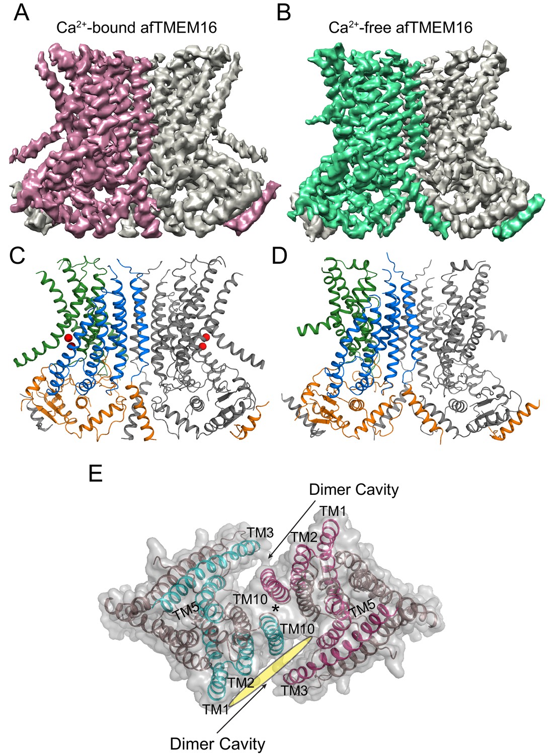
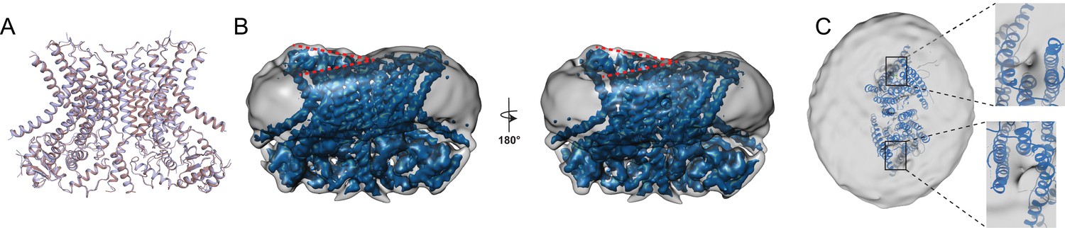
Structures of afTMEM16 in the presence and absence of Ca2+.
(A–B) Masked cryo EM density maps of afTMEM16 in the presence of 0.5 mM Ca2+ (A) or in Ca2+-free (B) conditions. For clarity, one monomer is shown in gray while the other is colored in red (A, 0.5 mM Ca2+) or green (B, 0 Ca2+). (C–D) atomic models of afTMEM16 reconstituted in nanodiscs in the presence of 0.5 mM Ca2+ (C) and in the absence of Ca2+ (D). For clarity one monomer is gray, in the other the cytosolic domain is orange, the permeation pathway is green and the remainder of the protein is blue. Ca2+ ions are shown as red spheres. (D) Top view of Ca2+-bound afTMEM16 shown as maroon ribbon inside its surface representation. The dimer cavities are labeled and one of the two is highlighted with a yellow oval. * denotes the protein’s twofold axis of symmetry between the two TM10’s. To illustrate the antiparallel orientation of the two dimer cavities, the cavity-lining helices (TM1, 2, 3, 5 and 10) from the two monomers are colored in cyan and red.
Figure 1—figure supplement 1
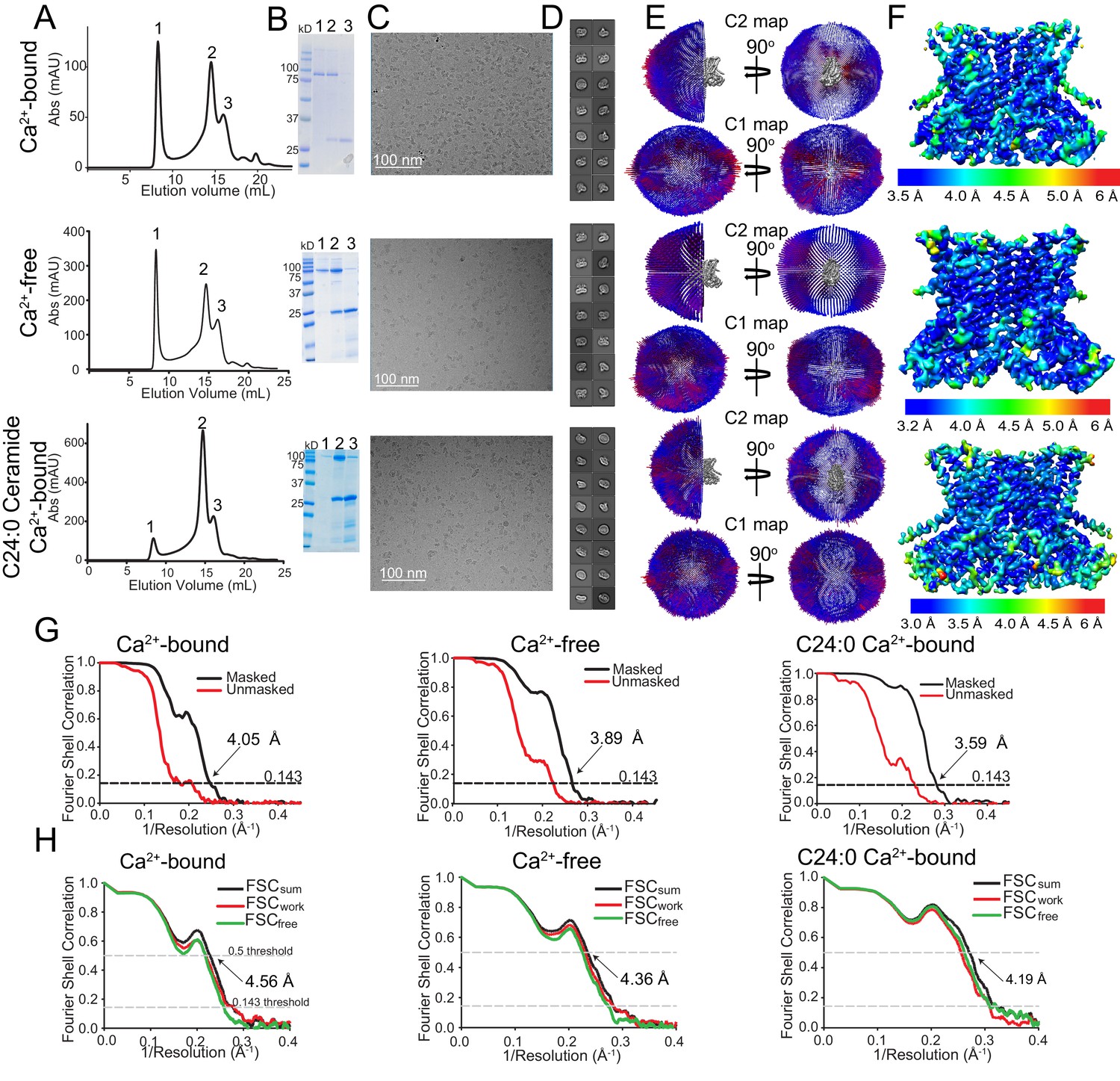
Cryo-EM characterization of afTMEM16/nanodisc complexes.
(A–F) Top:+0.5 mM Ca2+. Middle: 0 Ca2+. Bottom:+0.5 mM Ca2+ and + 5 mole% C24:0. (A) Size exclusion profile of afTMEM16 in MSP1E3 nanodiscs. (B) SDS gel of the indicated size exclusion peaks using precision plus kaleidoscope ladder. Molecular weight (MW) of afTMEM16 is 84.5 kD and MW of MSP1E3 is 32.5 kD. (C) Representative cryo-EM micrographs of vitrified afTMEM16/nanodisc complexes. (D) Representative 2D-class averages, box size 275 Å. (E) Angular distribution representation of final, signal-subtracted C2 or C1 maps, number of views at each angular orientation is represented by length and color of cylinders where red indicates more views. (F) Final masked reconstruction colored by local resolution calculated using the Bsoft program BlocRes (Heymann, 2001; Cardone et al., 2013). (G) FSC plot indicating the resolution at the 0.143 threshold of final masked (black) and unmasked (red) map of afTMEM16 in the presence of 0.5 mM Ca2+ (left) absence of Ca2+ (middle), and presence of 0.5 mM Ca2+ and five mole% C24:0 (right). (H) FSC curves of refined models versus maps of afTMEM16 reconstituted in nanodiscs in the presence of 0.5 mM Ca2+ (left), in the absence of Ca2+ (middle) or with 0.5 mM Ca2+ and five mole% C24:0 ceramide (right). Black traces: FSC curves for the refined model compared to the final masked reconstruction (FSCsum). Red traces: FSC curves for the modified, refined model compared to the masked half-map 1 (FSCwork, used during validation refinement). Green traces: FSC curves for the modified, refined model compared to the masked half- map 2 (FSCfree, not used during validation refinement). Dashed lines show FSC threshold used for FSCsum of 0.5 and for FSCfree/work of 0.143. Statistics for the EM analysis and model building are reported in Supplementary file 3.
Figure 1—figure supplement 2
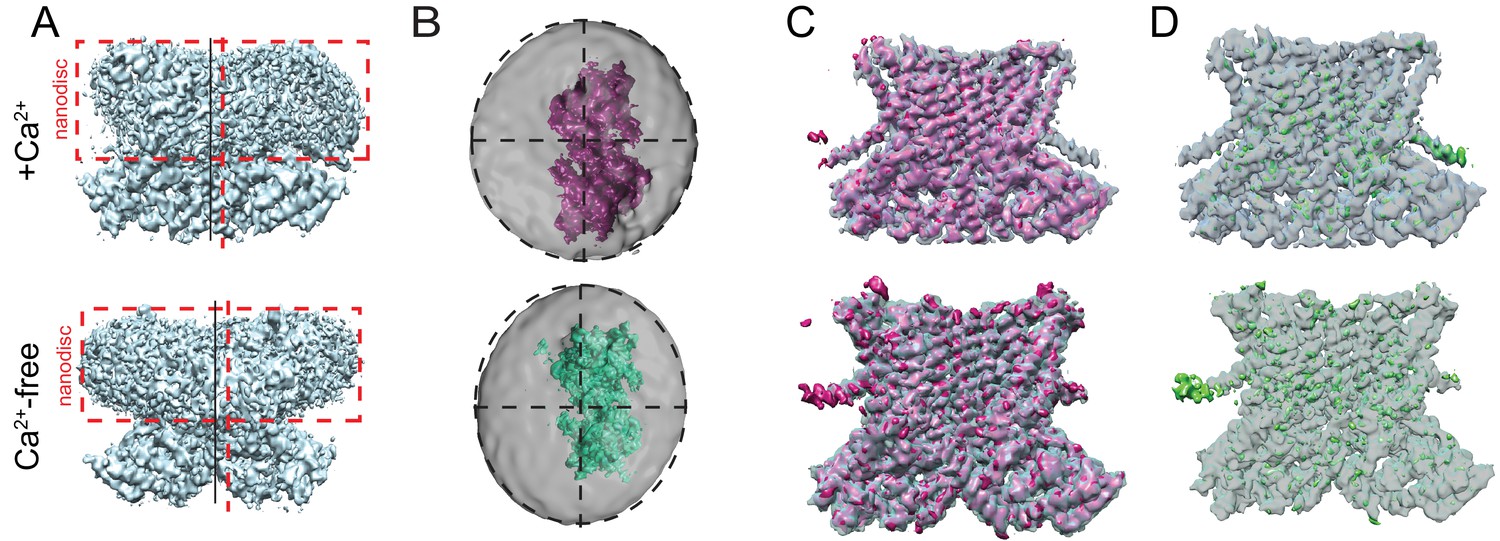
Asymmetry of afTMEM16-nanodisc complex.
(A) Unmasked final C1 map highlighting the non-centered positioning of the protein within the nanodisc in the presence (top) and absence (bottom) of Ca2+. Dashed red box is drawn around the nanodisc and dashed vertical red line shows the symmetry axis of the nanodisc. Vertical black line shows the symmetry axis of the protein. (B) Top views of the afTMEM16-nanodisc complexes for afTMEM16 +Ca2+ (top, pink) and afTMEM16 Ca2+-free (bottom, green). The masked final maps are shown inside unmasked maps, which were low pass filtered to 10 Å and are shown at σ = 0.25. Dashed circles indicate the oval outline of nanodisc and the dashed lines denote the axis of the oval to highlight the different position of the protein map relative to the nanodiscs. (C) Overlay of C1 (solid pink) and C2 (transparent gray) maps for the + Ca2+ (top) and 0 Ca2+ complexes (bottom). (D) The difference map between the C1 and C2 maps (green) is shown inside the C2 map (gray transparent).
Figure 1—figure supplement 3
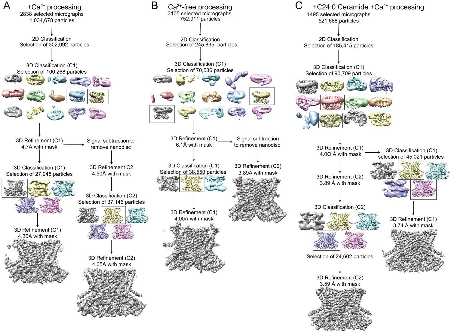
Cryo-EM data processing procedure for afTMEM16/nanodisc complexes.
(A–C) Data processing flow chart for +Ca2+ (A), Ca2+-free (B), and +C24:0 Ceramide +Ca2+ (C). Particles picked from manually inspected micrographs were sorted with 2D and 3D classification in C1 before particle polishing and final masked refinement. For the +Ca2+ and Ca2+-free structures, particles were further classified and refined in C2 following signal subtraction of the nanodisc density. See Materials and methods for detailed procedure.
Figure 1—figure supplement 4
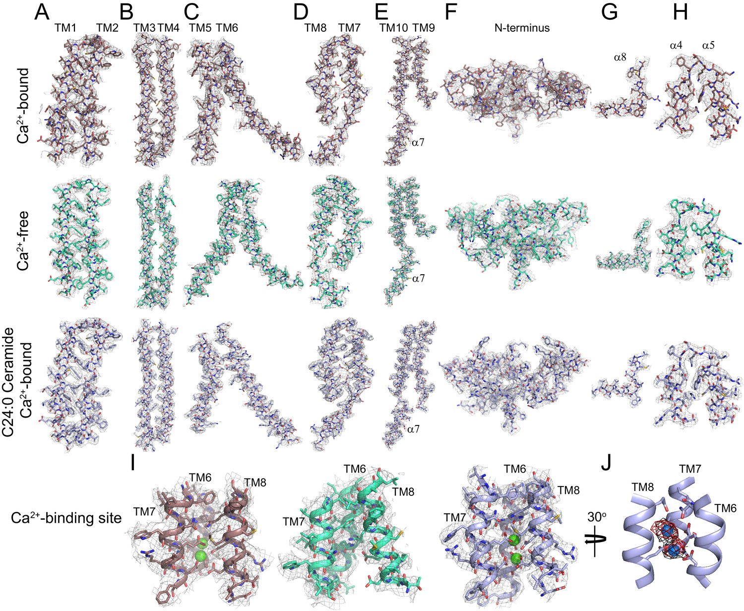
Representative cryo-EM density for afTMEM16 in 0.5 mM Ca2+, in 0 mM Ca2+ and in the presence of 0.5 mM Ca2+ and 5 mol% C24:0 Ceramide.
(A–I) The cryo-EM density (gray mesh) is overlaid with the respective atomic models (sticks), Ca2+-bound afTMEM16 is in maroon (top panels), Ca2+-free is in cyan (middle panels) and Ca2+-bound afTMEM16 in the presence of C24:0 Ceramide is in light blue (bottom panels). Heteroatoms are colored as follows: oxygen is red, nitrogen is blue, and sulfur is yellow. (A–E) Transmembrane domains TM1-10 and cytosolic 7. (F) N-terminus containing 1–3, α6 and β1–3. (G) Close up of the domain-swapped region α8. (H) Close up of the cytosolic helices α4–5. (I) Ca2+ binding site consisting of portions of TM6-8 with Ca2+ ions shown in green. (J) Placement of Ca2+ ions (green) in the +Ca2+ + C24:0 Ceramide structure inside EM density map (black) and omit difference map (red).
Figure 1—figure supplement 5
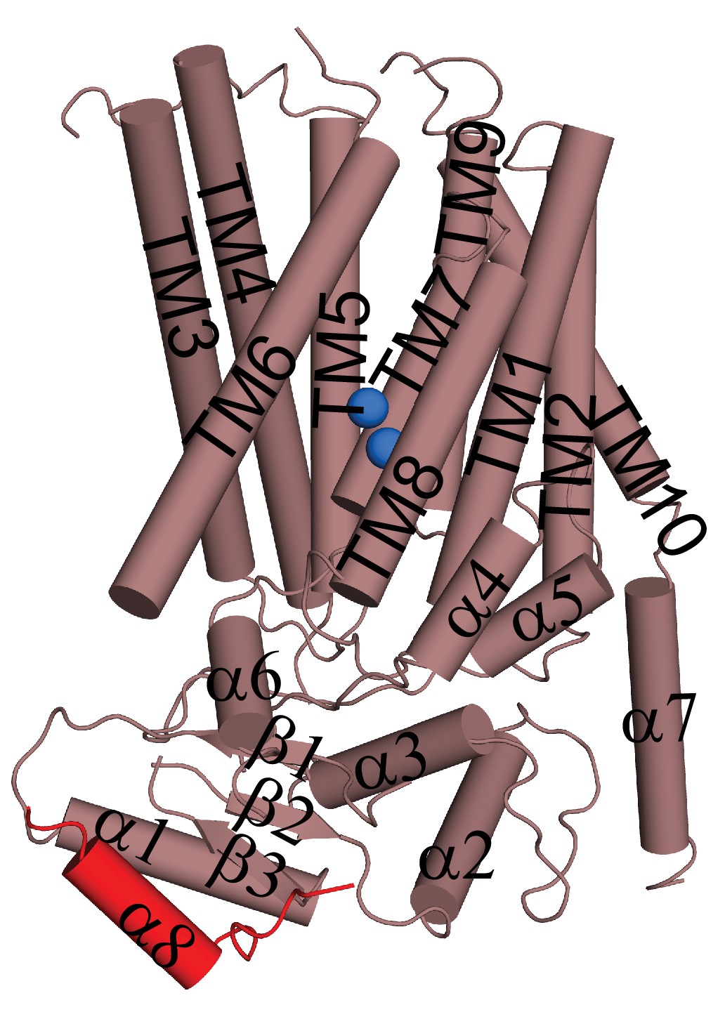
Helical organization of afTMEM16.
Helices are shown as cylinders and the domain-swapped α8 from the other monomer is shown in red. Ca2+ ions are shown as blue spheres.
Figure 1—figure supplement 6
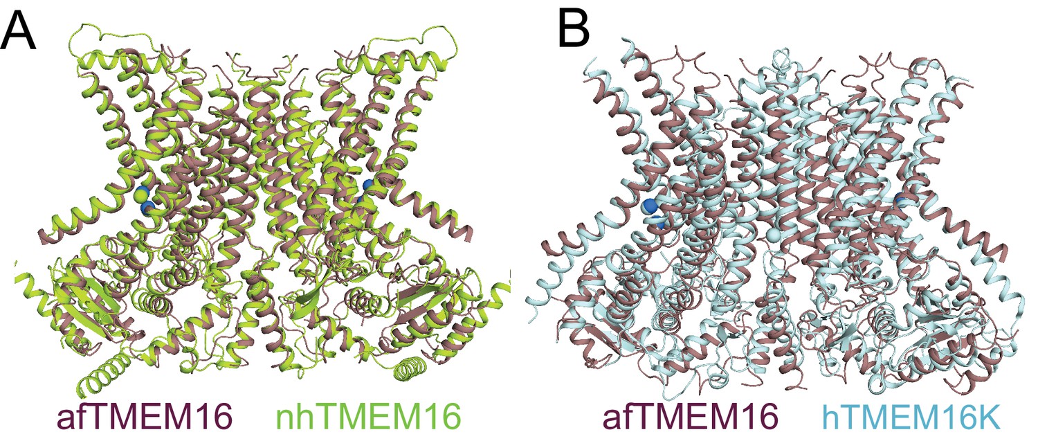
afTMEM16 in nanodiscs is very similar to nhTMEM16 and human TMEM16K in detergent.
(A–B) Structural alignment of the atomic models of Ca2+-bound afTMEM16 in nanodiscs (purple) and nhTMEM16 in detergent (limon, PDBID 4WIS, Cα RMSD 1.92 Å) of hTMEM16K in detergent (light blue, PDBID 5OC9, Cα RMSD 3.69 Å).
Figure 2 with 1 supplement

Ca2+-induced changes in afTMEM16.
Structural alignment of afTMEM16 in the presence of 0.5 mM Ca2+ (maroon) and absence of Ca2+ (cyan) (blue sphere). Left: conformational changes in the cytosolic domain, Right: conformational changes in the lipid permeation pathway. Arrows indicate direction of movement from the Ca2+-bound to the Ca2+-free conformations.
Figure 2—figure supplement 1
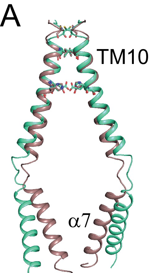
afTMEM16 dimer interface.
(A) Structural alignment of the TM10-α7 dimer interface of afTMEM16 in Ca2+-bound (maroon) and Ca2+-free (cyan) conformations.
Figure 3 with 2 supplements
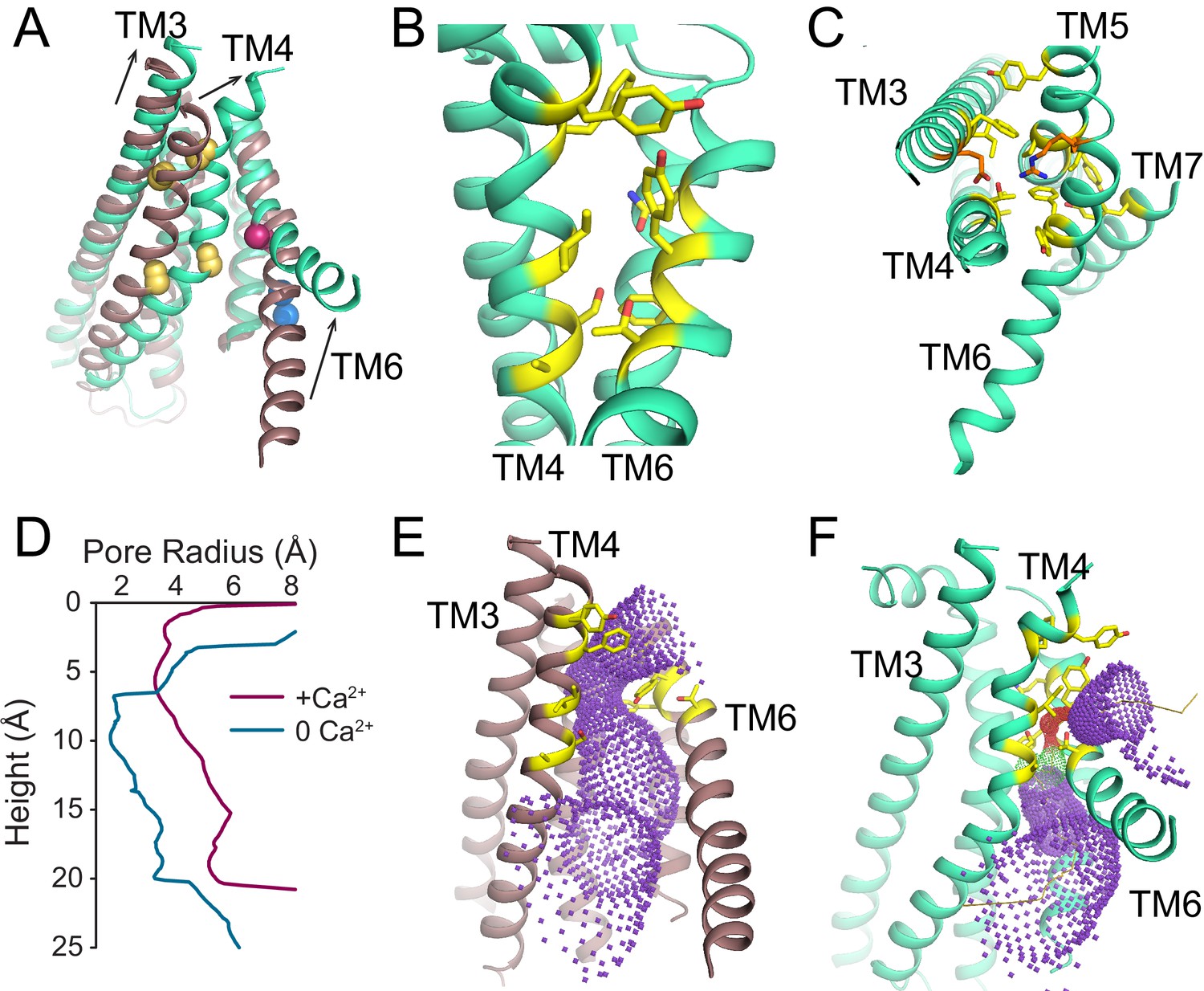
Ca2+-dependent rearrangements of the lipid permeation pathway.
(A) Structural alignment of the lipid pathway with afTMEM16 in the presence (maroon) or absence (cyan) of 0.5 mM Ca2+. The color scheme is the same throughout the figure. Arrows indicate direction of movement from the Ca2+-free to the Ca2+-bound conformations. The lipid permeation pathway is constricted by rearrangements of TM4 around P324 and P333 (shown as yellow spheres in both structures) and TM6 at A437 (shown as a red sphere in both structures). (B) Close-up view of the closed permeation pathway, residues at the interface with the membrane are shown as yellow sticks. (C) Top view of the permeation pathway in the absence of Ca2+. Residues pointing inside the pathway are shown as yellow sticks. The interacting charged pair E305 and R425 are shown as orange sticks. (D) Diameter of the afTMEM16 lipid pathway in the presence (maroon) and absence (cyan) of Ca2+. The diameter was estimated using the HOLE program (Smart et al., 1996). (E–F) Accessibility of the lipid permeation pathway estimated using the program HOLE in the presence (E) or absence (F) of Ca2+. Purple denotes areas of diameter d > 5.5 Å, yellow areas where 5.5 < d < 2.75 Å and red areas with d < 2.75 Å.
Figure 3—figure supplement 1
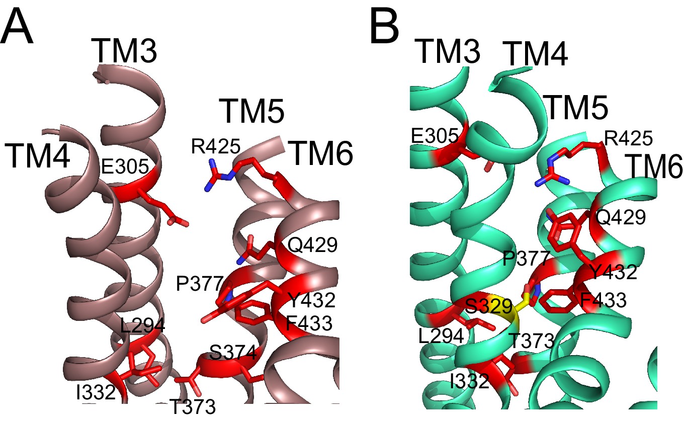
Residues important for scrambling are mapped onto afTMEM16 open and closed permeation pathways.
(A–B) The position of recently identified residues important for lipid scrambling by nhTMEM16 (red sticks) (Jiang et al., 2017; Lee et al., 2018) are mapped onto the afTMEM16 Ca2+-bound (A) and Ca2+-free (B) structures. Mutation of theses residues reduces the rate of scrambling by >100 fold. Critical positions cluster at the rearranging interfaces between helices TM3-6. Of note is V337 (S329 in afTMEM16, shown in yellow) whose mutation to tryptophan increases scrambling activity in the absence of Ca2+. In the Ca2+-free structure, this residue is positioned at the TM4-TM6 contact point, suggesting that this substitution might prevent closure of the pathway.
Figure 3—figure supplement 2
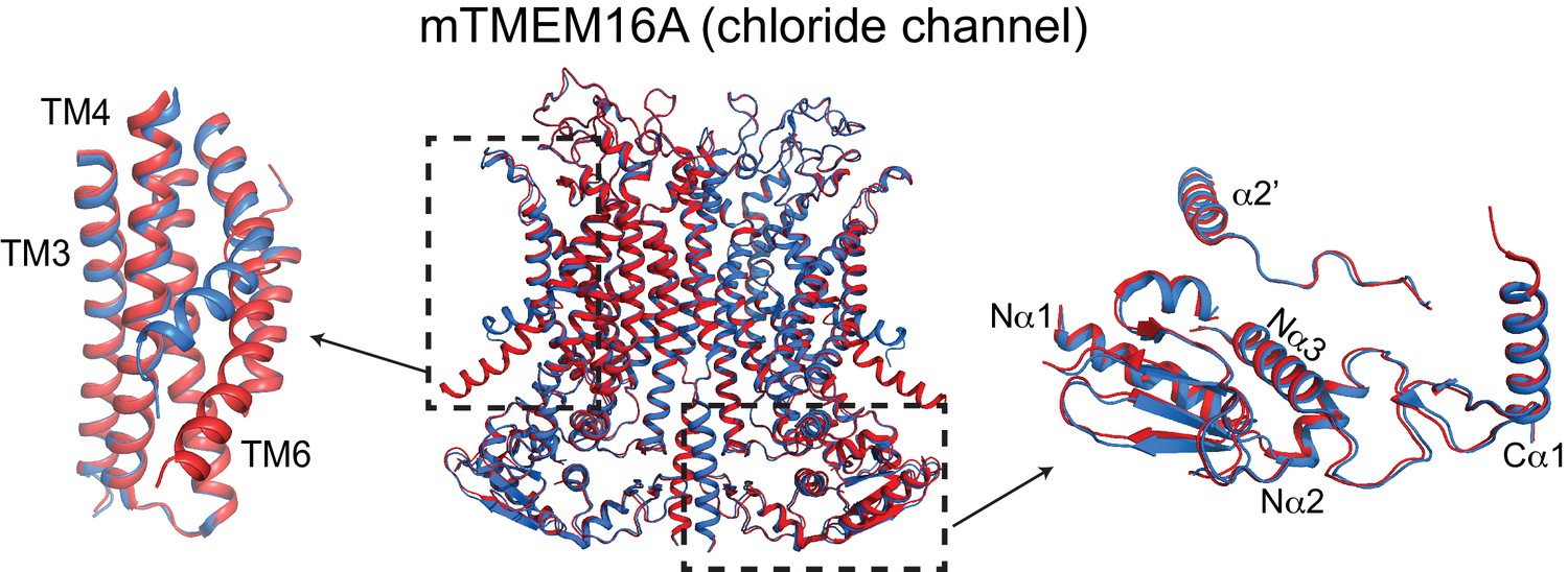
Ca2+-induced changes in TMEM16A.
Structural alignment of TMEM16A in the presence of 0.5 mM Ca2+ (PDBID: 5OYB, red) and absence of Ca2+ (PDBID: 5OYG, blue). Left: conformational changes in ion permeation pathway. Right: view of cytosolic domains showing a lack of movement upon Ca2+-binding.
Figure 4
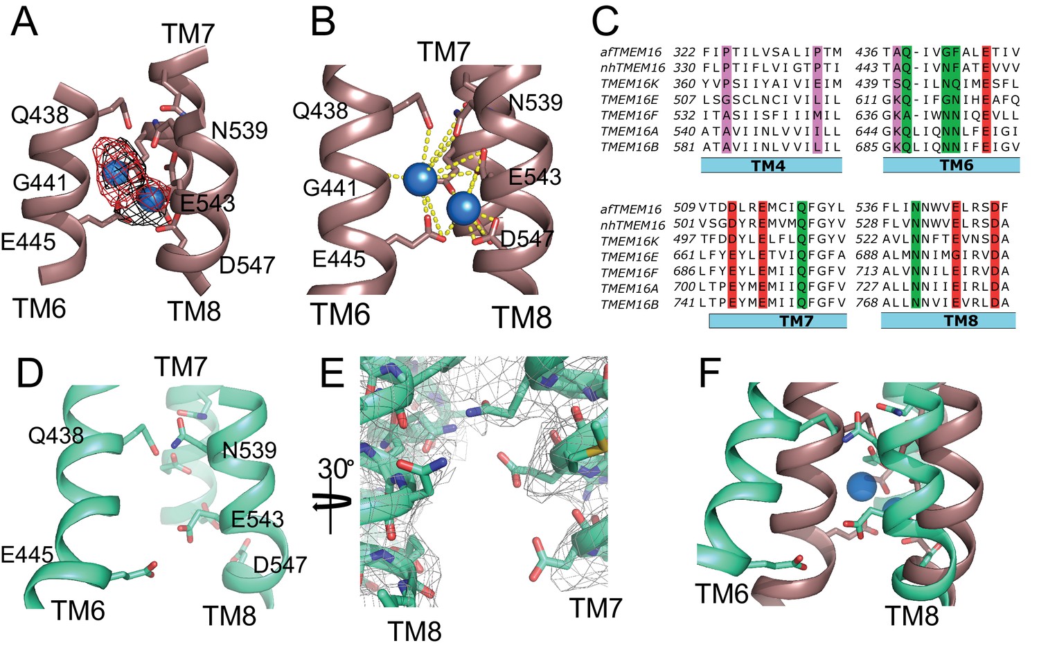
afTMEM16 Ca2+-binding site and conformational changes.
(A) Close up view of the Ca2+-binding site, with key coordinating residues shown as sticks. The density corresponding to the Ca2+ ions (blue spheres) from the experimental map is shown in black and the density from the calculated omit difference map is shown in red. The peak density corresponding to the Ca2+ ions in the omit difference maps (red mesh) is σ = 13 and 7. (B) Ca2+ coordination in afTMEM16. (C) Structure-based sequence alignment of the Ca2+-binding site and gating region of TMEM16 proteins. The alignment was generated using PROMALS3D (Pei and Grishin, 2014). Highlighted residues: conserved acidic (red) or polar (green) side chain in Ca2+ binding site, and the residues around which TM4 and TM6 bend (pink). (D) Close-up of the Ca2+-binding site in the absence of ligand. Coordinating residues on TM6 and TM8 are labeled. (E) EM density of residues lining the Ca2+-binding site in the absence of Ca2+ highlighting the lack of density for Ca2+ ions. (F) Structural alignment of the binding site with and without Ca2+.
Figure 5 with 4 supplements
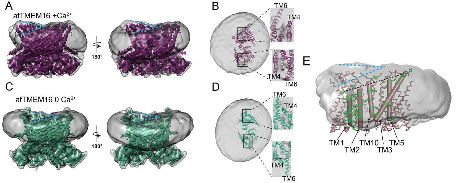
afTMEM16 affects the surrounding membrane.
(A and C) The unmasked maps (gray) of the afTMEM16/nanodisc complex in the presence (A) and absence of Ca2+ (C) are shown low pass filtered to 10 Å at σ = 0.4 with front (left panels) and back (right panels) views. The masked map of the afTMEM16 scramblase in 0.5 mM Ca2+ (A), in purple) or in 0 Ca2+ (C), in green) are shown inside the respective unmasked maps. Blue dashed lines highlight the bending at the dimer cavities. (B and D) Top view of the unmasked map (grey) with (B) and without (D) Ca2+ low-pass filtered to 10 Å at σ = 0.1 with the respective atomic models shown as ribbons inside. Insets show close-up views of the nanodiscs density at the permeation pathways. Note that the insets are displayed at a tilted angle compared to the top views to visualize the lipid pathway. (E) Bending of the outer leaflet at the dimer cavities in the presence of 0.5 mM Ca2+. The low-pass filtered map of the complex (from A) was segmented and the isolated nanodisc density is shown. The afTMEM16 transmembrane region is shown in ribbon with the helices lining one dimer cavity (TM1, 2, 3, 5, and 10) in cartoon representation. Aromatic residues are shown as green sticks. Blue dashed lines trace the upper membrane leaflet at the two sides of the lipid permeation pathway highlighting the opposite slant. Black dashed line traces the slope of the helices lining the dimer cavity.
Figure 5—figure supplement 1
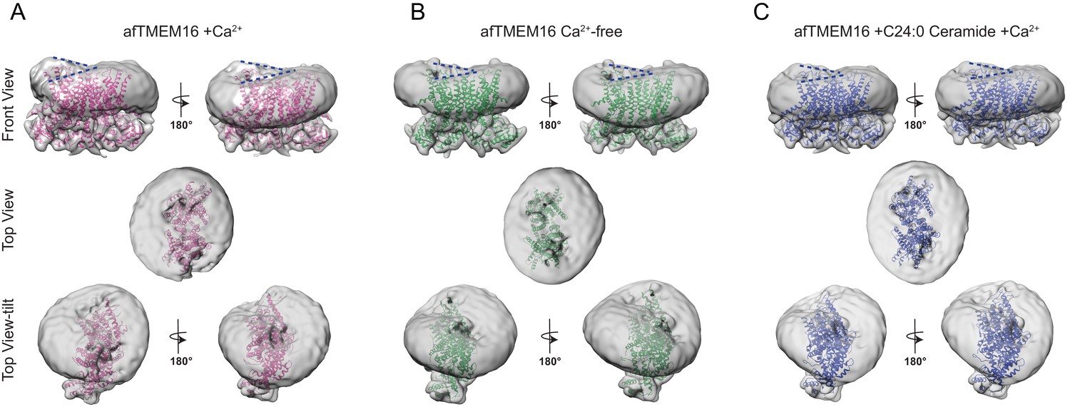
Ca2+-dependent and Ca2+-independent effects of afTMEM16 on nanodisc density.
(A–C) The unmasked maps of the afTMEM16/nanodisc complex in the presence of 0.5 mM Ca2+ (A), in Ca2+-free conditions (B) and with 0.5 mM Ca2+ and 5 mol% C24:0 Ceramide (C) are shown low-pass filtered to 10 Å and at σ = 3.5. The respective atomic models are shown inside in pink (0.5 mM Ca2+, (A)), green (Ca2+-free, (B)) and blue (0.5 mM Ca2+ and 5 mol% C24:0 Ceramide, (C)). Top panels: front and back (rotated 180o) views; middle: top views; bottom: top views tilted by ~30o relative to the middle panels to visualize the permeation pathway in each monomer (the two panels are rotated by 180o). Dashed blue lines in the top panels trace the membrane bending near the dimer cavities. Note how similar bending is observed in the front and back views.
Figure 5—figure supplement 2
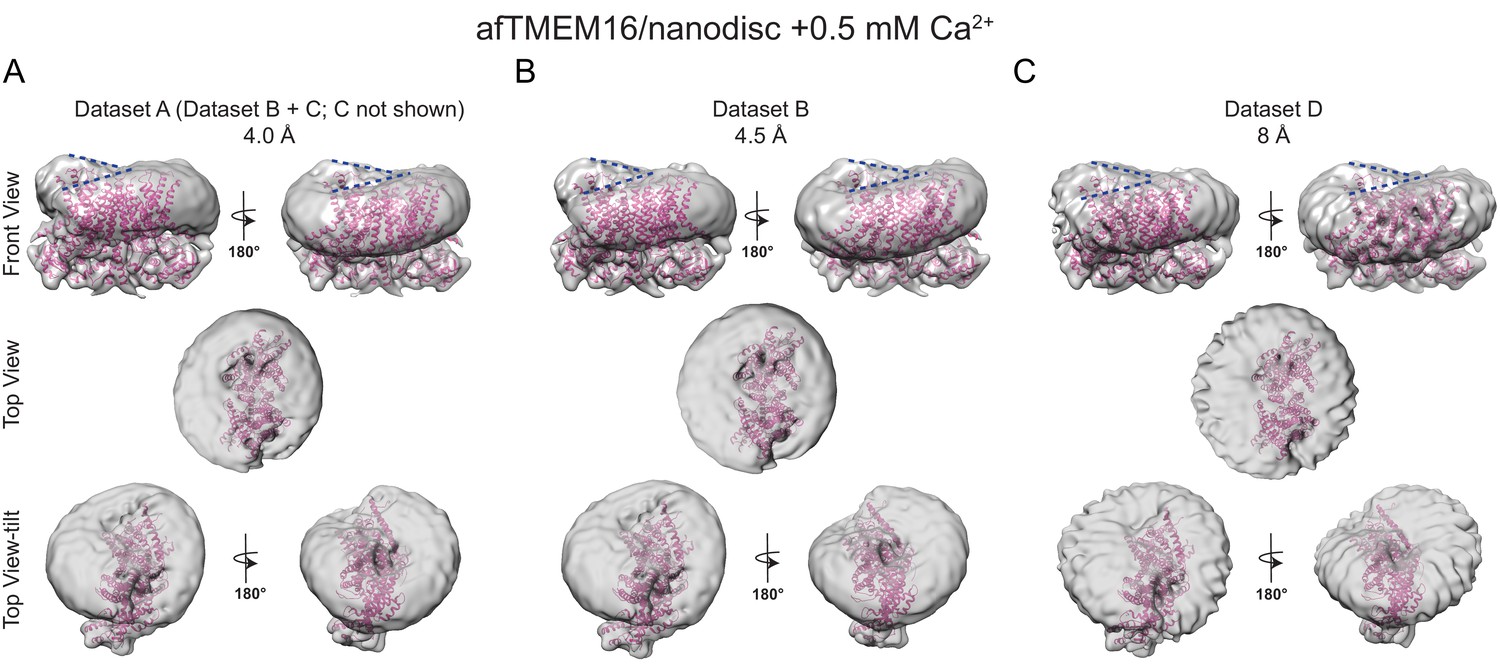
The effects of Ca2+-bound afTMEM16 on the surrounding membrane are seen in three independent datasets with varying resolutions.
(A–C) The unmasked maps of afTMEM16/nanodisc complex in the presence of 0.5 mM Ca2+ determined from three datasets are shown low-pass filtered to 10 Å and at σ = 3.5. The high-resolution afTMEM16 +Ca2+atomic model (pink) is shown inside the unmasked maps. (A) the map derived from the 4.0 Å resolution dataset (dataset A, Supplementary file 1) (B) the map obtained from the processing of dataset B (Supplementary file 1) resulting in a map with a resolution of 4.5 Å; (C) 3D reconstruction from dataset D (Supplementary file 1) that resulted in a map with a resolution of ~8 Å. Top: front and back (rotated 180o) views; middle: top views; bottom: top views tilted by ~30o relative to the middle panels to visualize the permeation pathway in each monomer (the two panels are rotated by 180o). Dashed blue lines in the top panels trace the membrane bending near the dimer cavities. Note how similar bending is observed in the front and back views.
Figure 5—figure supplement 3
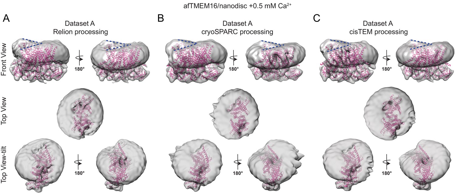
The effects of Ca2+-bound afTMEM16 on the surrounding membrane do not depend on the processing algorithm.
(A–C) The unmasked maps of the afTMEM16/nanodisc complex in the presence of 0.5 mM Ca2+ determined from dataset A (see Supplementary file 1) are shown low-pass filtered to 10 Å and at σ = 3.5. The high-resolution afTMEM16 +Ca2+atomic model (pink) is shown inside the unmasked maps. The maps were obtained with processing the dataset in Relion (A), cryoSPARC (B) or cisTEM (C). Top: front and back (rotated 180o) views; middle: top views; bottom: top views tilted by ~30o relative to the middle panels to visualize the permeation pathway in each monomer (the two panels are rotated by 180o). Dashed blue lines in the top panels trace the membrane bending near the dimer cavities. Note how similar bending is observed in the front and back views.
Figure 5—figure supplement 4
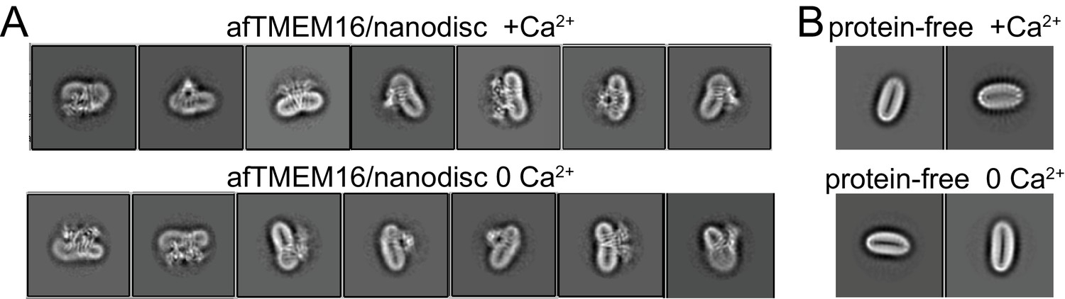
Altered membrane organization induced by activation of afTMEM16.
(A–B) Close-up view of representative 2D classes (box size 275 Å) of Ca2+-bound (0.5 mM) (top) and Ca2+-free (bottom) nanodisc-reconstituted afTMEM16 (taken from Figure 1 —figure supplement 1D). Note how the bending of the nanodisc induced by afTMEM16 is visible in the 2D classes. (B) Close up view of 2D class averages (box size 275 Å) of empty (without protein) nanodiscs from the +Ca2+ (top) and Ca2+-free (bottom) data sets. Note how the empty nanodiscs are flat and not bent.
Figure 6 with 2 supplements
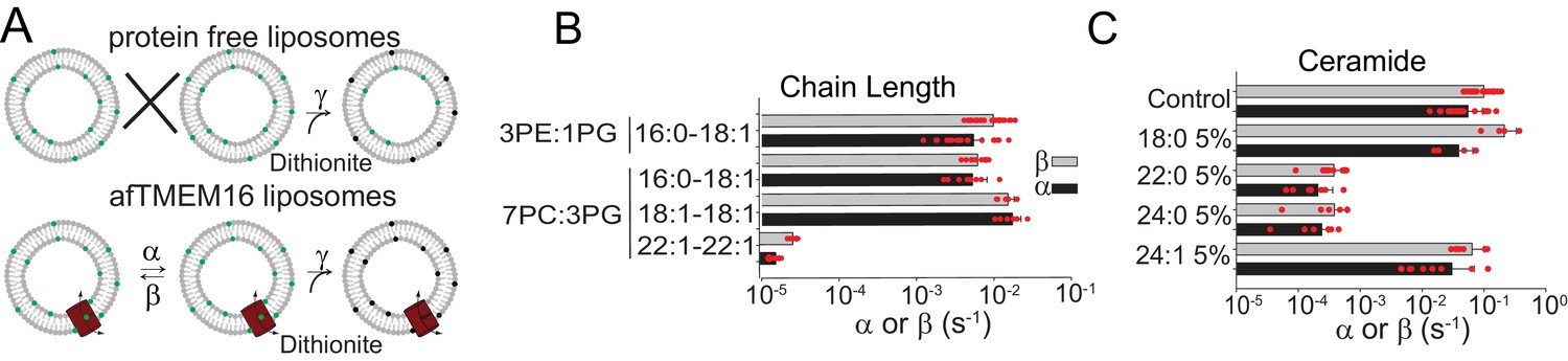
Dependence of afTMEM16 on membrane lipids.
(A) Schematic of the in vitro scramblase assay. Liposomes are reconstituted with NBD-labeled phospholipids (green) that distribute equally in the two leaflets. Addition of extraliposomal sodium dithionite reduces the NBD fluorophore (black), causing 50% fluorescence loss in protein-free vesicles (top panel). When a scramblase is present (bottom panel), all NBD-phospholipids become exposed to dithionite, resulting in complete loss of fluorescence (Malvezzi et al., 2013). (B–C), Forward (α, black) and reverse (β, grey) scrambling rate constants of afTMEM16 in 0.5 mM Ca2+ as a function of lipid chain length (B) or addition of 5 mole% of different ceramides (C). Rate constants were determined by fitting the fluorescence decay time course to Eq. 1. For the chain length experiments liposomes were formed either from a 3 POPE: 1 POPG or a 7 POPC: 3 POPG mixture (B). A 3 POPE: 1 POPG mixture was used for the reconstitutions containing ceramide lipids (C). Data is reported as mean ±S.D. Red circles denote individual experiments. Values and exact repeat numbers are reported in Supplementary files 2,4.
Figure 6—figure supplement 1
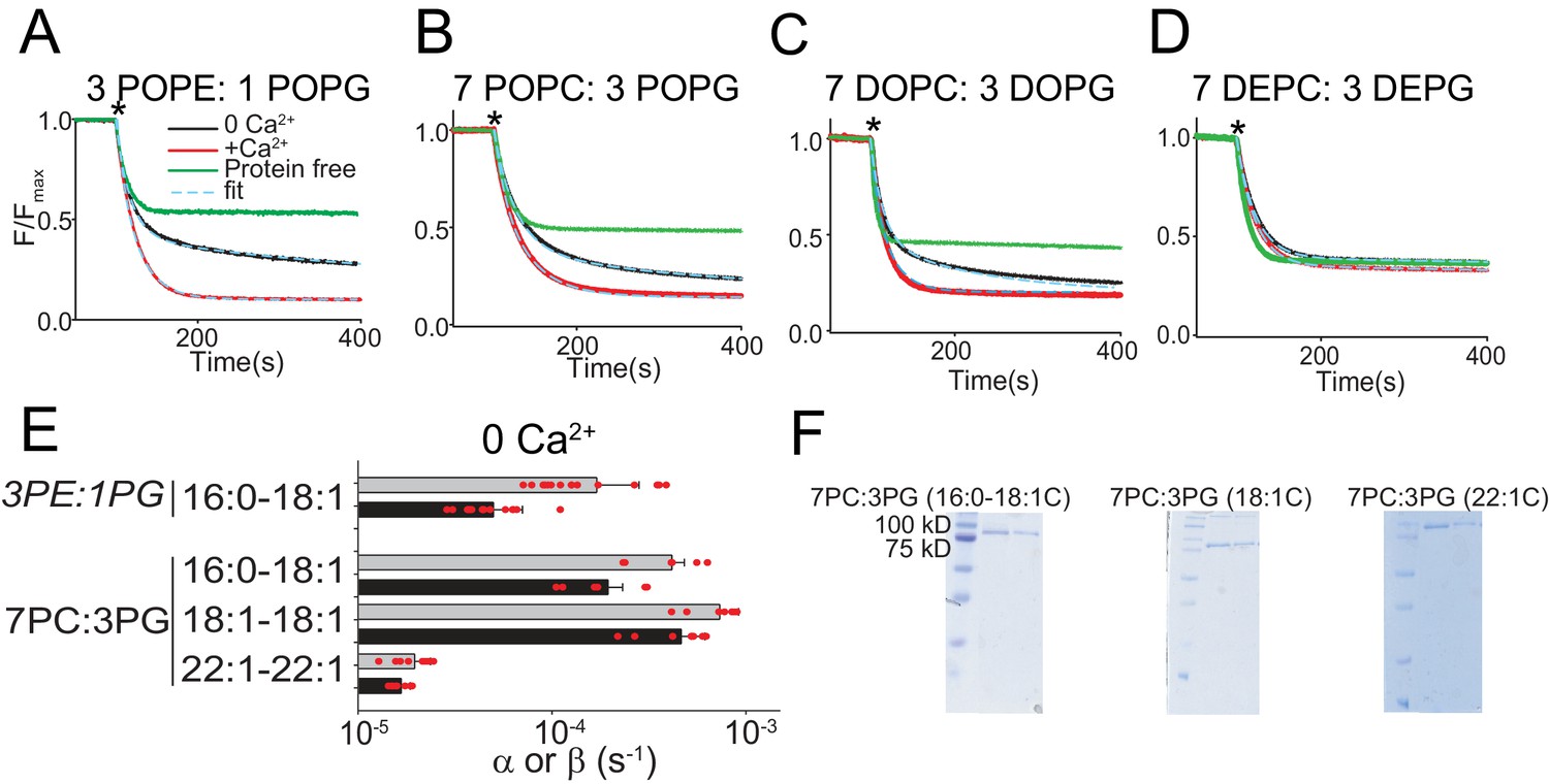
Functional modulation of lipid scrambling by acyl chain length.
(A–D) Representative time courses of dithionite-induced fluorescence decay in protein-free liposomes (green) or in afTMEM16 proteoliposomes with (red) or without (black) Ca2+. Cyan dashed lines represent the fit to Eq. 1 (Malvezzi et al., 2018). * denotes addition of dithionite. Liposomes were formed from 3 POPE: 1 POPG (A), 7 POPC: 3 POPG (B), 7 DOPC: 3 DOPG (C), or 7 DEPC: 3 DEPG (D) mixtures. Please note that in 7 DEPC: 3 DEPG liposomes (D) the steady state value of the fluorescence decay of the protein-free liposomes is below 0.5. This reflects an asymmetric initial distribution of the NBD-PE probe rather than compromised liposome integrity, as the fluorescence reaches a plateau and remains stable for the duration of the experiment. (E) Forward (α, black) and reverse (β, gray) scrambling rate constants in the absence of Ca2+ as a function of lipid chain length. Data in panel E is reported as mean ±SD. Red circles denote individual experiments. Values and exact repeat numbers are reported in Supplementary file 3 . (F) SDS-PAGE gels of liposomes containing afTMEM16 throughout the reconstitution confirming the presence of the protein in the conditions without scrambling activity as compared to the associated control 22:1C PC-PG (right). Samples were taken from the reconstitution after the first biobead change (left) and after the last (right). In all gels, the final band represents the protein present in the liposomes when the experiment was completed.
Figure 6—figure supplement 2
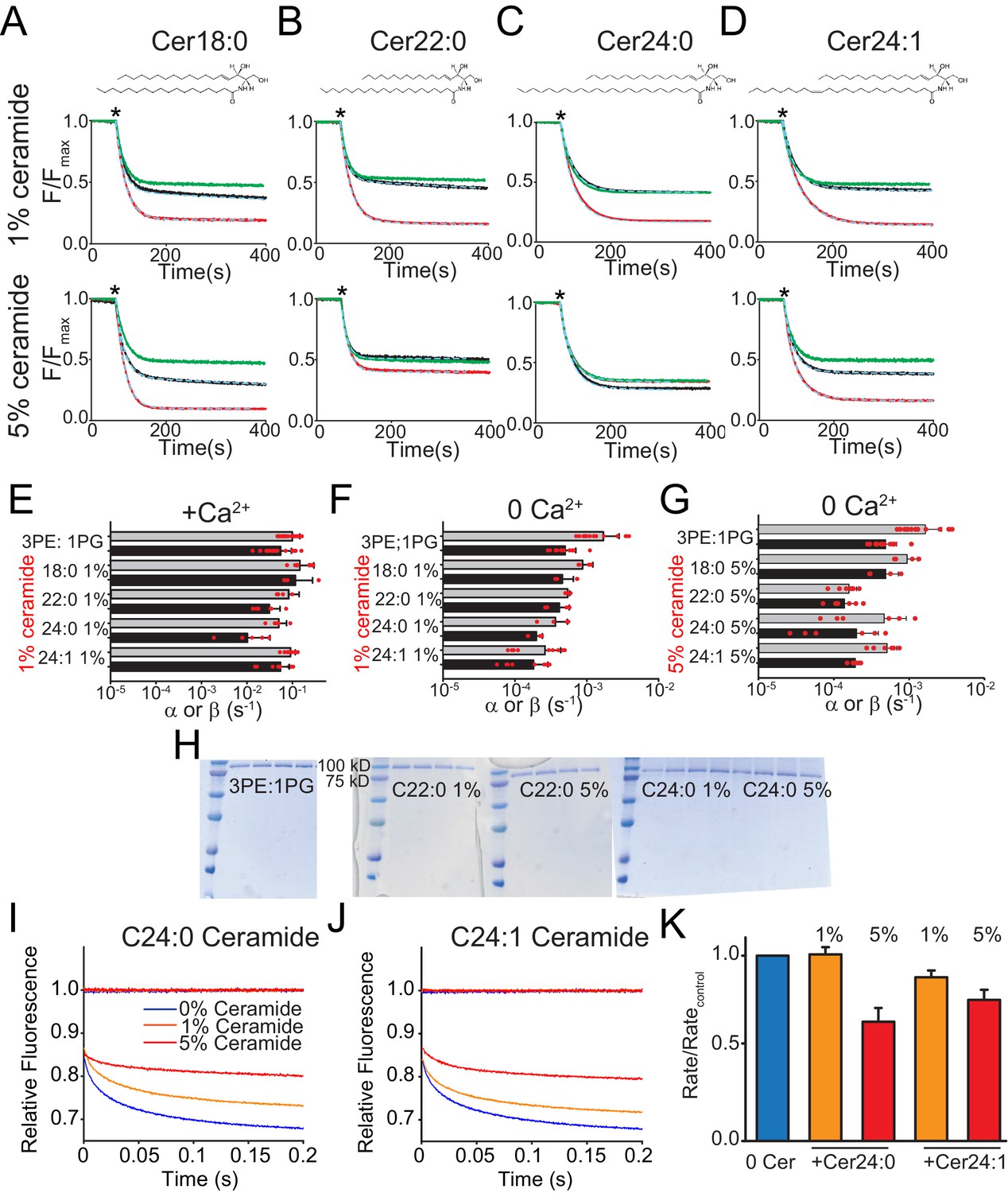
Functional modulation of lipid scrambling by addition of ceramide lipids.
(A–D) Representative time courses of dithionite-induced fluorescence decay in control liposomes formed from a 3 POPE: 1 POPG mixtures with C18:0 Ceramide (A), C22:0 Ceramide (B), C24:0 Ceramide (C) or C24:1 Ceramide (D) at one mole% (top panels) or at five mole% (bottom panels). Please note that in the presence of 5% C24:0 Ceramide (C) the steady state value of the fluorescence decay of the protein-free liposomes is below 0.5. This does not reflect compromised liposome integrity, as evidenced by the fact that the fluorescence reaches a plateau and remains stable for the duration of the experiment, rather it reflects an asymmetric initial distribution of the NBD-PE probe. (E–G) Forward (α, black) and reverse (β, grey) scrambling rate constants of afTMEM16 with one mole% ceramides with (E) or without Ca2+ (F) or with 5 mole% Ceramide and without Ca2+ (G). Data in panels E-G is reported as mean ±SD. Red circles denote individual experiments. Values and exact repeat numbers are reported in Supplementary file 4. (H) SDS-PAGE gels of liposomes containing afTMEM16 throughout the reconstitution confirming the presence of the protein in the conditions without scrambling activity as compared to the associated control (C22:0 ceramide-middle and C24:0 ceramide-right). Samples were taken from the reconstitution after each of the four biobead changes. In all gels, the final band represents the protein present in the liposomes when the experiment was completed. (I–J) Representative time course of gramicidin A (gA)-mediated Tl+-induced quenching of ANTS in 3 POPE:1 POPG large unilamellar vesicles + C24:0 ceramide (I) or C24:1 ceramide (J). Blue trace: control –no ceramide; orange trace: 1% ceramide; red trace: 5% ceramide. (K) Normalized rate of the Tl+-induced fluorescence quenching. The quenching rate was determined by fitting a stretched exponential (Eq. 3) to the fluorescence time course in I–J). The quenching rate reflects the gA monomer↔dimer equilibrium that is affected by the chemicophysical properties of the membrane where a reduction in the rates reflects a stiffening and/or reduction in fluidity of the membrane.
Figure 7 with 1 supplement
Structure of afTMEM16 in the presence of C24:0 ceramide.
(A) Structural alignment of Ca2+-bound afTMEM16 with (light blue) and without C24:0 ceramide (maroon) with a Cα r.m.s.d. <1 Å. (B) The unmasked maps (gray) of the afTMEM16/nanodisc complex in the presence of 0.5 mM Ca2+ and 5 mol% C24:0 ceramide is shown low pass filtered to 10 Å at σ = 0.4 with front (left panel) and back (right panel) views. The masked map of the afTMEM16 scramblase in 0.5 mM Ca2+ and 5 mol% C24:0 ceramide is shown inside the respective unmasked maps. Red dashed lines highlight the membrane bending. (C) Top view of unmasked map (grey) low pass filtered to 10 Å at σ = 0.1 with the atomic models inside. Insets show the density at the permeation pathway. Note that the insets are displayed at a tilted angle compared to the top views to visualize the changes in density at the lipid pathway.
Figure 7—figure supplement 1
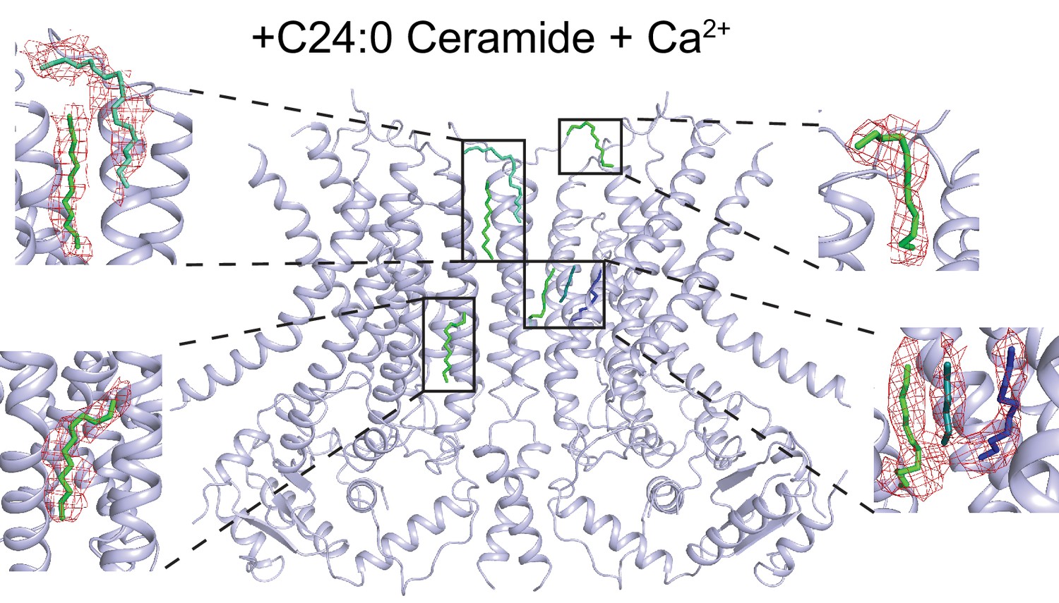
Lipid-like density in the dimer cavity.
Atomic model of afTMEM16 in in the presence of 0.5 mM Ca2+ and 5 mole% C24:0 Ceramide with location of lipid acyl chains within the side dimer cavity. Insets show acyl chains colored by ligand ID (D12-green, D10-blue, 8K6-cyan, OCT-teal) into the difference map density (in red) between the experimental density map and the theoretical map calculated from the model with lipids omitted. Only the lipids in one dimer cavity are shown for clarity.
Figure 8 with 3 supplements
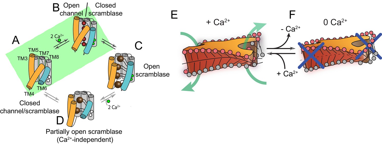
Proposed mechanisms for gating and membrane remodeling by TMEM16 scramblases.
(A–D) Ca2+-dependent gating scheme for TMEM16 scramblases. The α helices lining the lipid pathway and Ca2+-binding site (TM3-8) are shown as cylinders. The two gating elements (TM3-4 and TM6) are colored in orange and blue, respectively. When the Ca2+ binding sites are empty TM4 and TM6 are bent and occlude the pathway, resulting in a closed scramblase (PDBID: 6DZ7) (A). Upon Ca2+ binding, TM6 straightens and partly disengages from TM4, giving rise to a pathway that is closed to lipids but that can potentially allow ion permeation (a mTMEM16A-like state, PDBID:5OYG) (B). Rearrangement of TM6 promotes the straightening of TM4, resulting in an open lipid pathway (PDBID: 4WIS, 6E0H) (C). Straightening of TM4 in the absence of Ca2+, gives rise to a partially open lipid pathway that might allow the experimentally observed Ca2+-independent lipid scrambling (Malvezzi et al., 2013) (D). If the straightening of TM4 is energetically unfavorable, the protein is restricted to visiting only states (A) and (B), green shaded area. This would give rise to the observed Ca2+-dependent gating behavior of the TMEM16 channels. (E–F) proposed mechanism for membrane remodeling by the afTMEM16 dimer. The slanted architecture of the dimer cavity primes the membrane by bending it in opposite directions on the two sides of the lipid translocation pathway. In the presence of Ca2+ the pathway is open, enabling the formation of a membrane area that is thin and forming a conduit through which lipid headgroups can translocate between the two leaflets (E). In the absence of Ca2+ the pathway is closed preventing lipid scrambling (F).
Figure 8—figure supplement 1
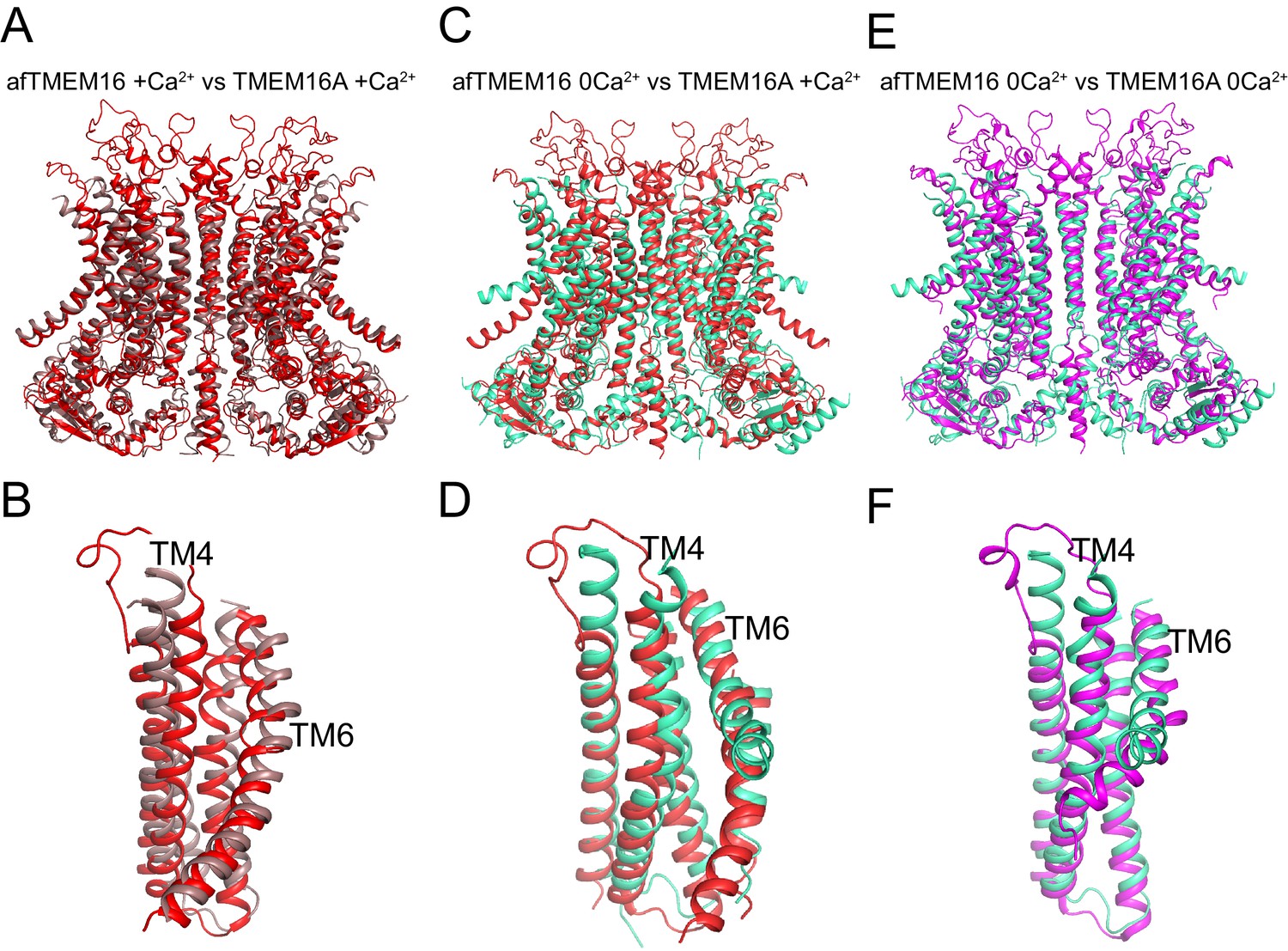
Structural comparison of Ca2+-bound and Ca2+-free afTMEM16 and TMEM16A.
(A–B) Alignment of Ca2+-bound afTMEM16 (maroon) and Ca2+-bound TMEM16A (red, PDBID: 5OYB). A close-up view of the pathway is shown in (B) to highlight the closure of the permeation pathway in the TMEM16A channel by a rearrangement of TM4. (C–D) Alignment of Ca2+-free afTMEM16 (cyan) and Ca2+-bound TMEM16A (red). A close-up view of the pathway is shown in (D) to highlight how the TM4 helices adopt similar conformations. (E–F) Alignment of Ca2+-free afTMEM16 (cyan) and Ca2+-free TMEM16A (magenta, PDBID 5OYG). A close-up view of the pathway is shown in (F) to highlight how the TM4 helices adopt similar conformations and the TM6 bend at the same points. Note the different orientations of the intracellular portions of the TM6 in the two structures in the absence of Ca2+.
Figure 8—figure supplement 2
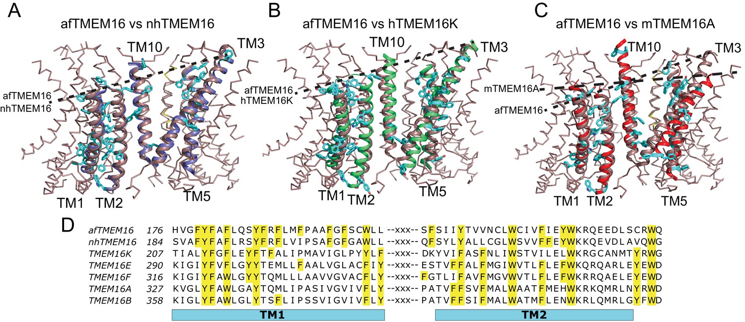
Architecture of the dimer cavity of TMEM16 proteins.
(A–C) Structural alignment of the dimer cavities of nhTMEM16 (purple) (A), hTMEM16K (green) (B), or mTMEM16A (red) (C) to afTMEM16 (maroon). The transmembrane region of afTMEM16 is shown as ribbon. The five cavity-lining helices (TM1, TM2, and TM10 from one monomer, TM3 and TM5 from the other) from both displayed structures are shown in cartoon representation. Aromatic side chains from nhTMEM16 (A), hTMEM16K (B), and mTMEM16A (C) lining the cavity are shown as cyan sticks. The TM1 comprises 29 total residues, of which 11 are aromatic in afTMEM16, 10 in nhTMEM16, 8 in TMEM16K and 7 in TMEM16A. (D) Conservation of the aromatic residues in TM1 and TM2 within the TMEM16 family. Sequence alignment was generated using PROMALS3D (Pei and Grishin, 2014). Aromatic residues in TM1 and TM2 are highlighted in yellow.
Figure 8—figure supplement 3
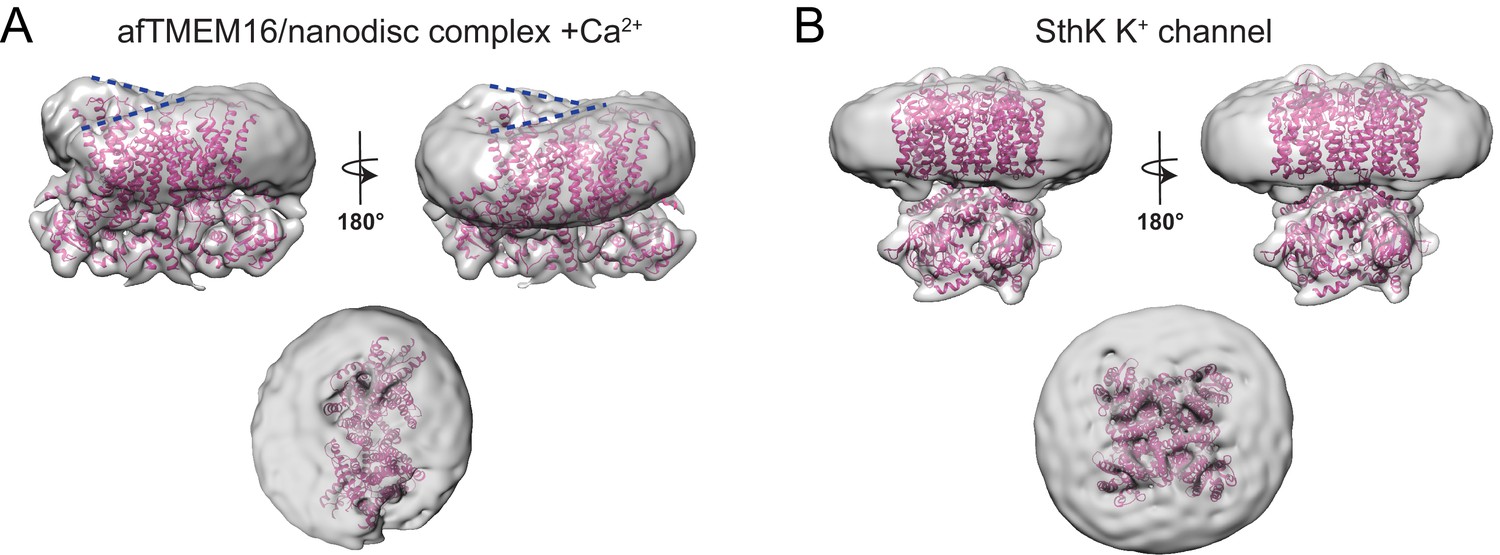
Effects of afTMEM16 on the nanodsic membrane are not observed in other unrelated membrane proteins.
(A–B) The unmasked maps of the afTMEM16/nanodisc complex in the presence of 0.5 mM Ca2+ (A) and of the apo SthK potassium channel/nanodisc complex (Rheinberger et al., 2018) are shown low-pass filtered to 10 Å and at σ = 3.5. The respective atomic models are shown inside in pink (0.5 mM Ca2+, A; SthK apo PDBID 6CJQ, (B). Top panels: front and back (rotated 180o) views; Middle: top views; Dashed blue lines in the top panels in (A) trace the membrane bending near the dimer cavities. Note how similar bending is observed in the front and back views.
Videos
Video 1
Ca2+-activation of afTMEM16.
Morph between Ca2+-free and Ca2+-bound conformations of afTMEM16. For clarity one monomer is shown in gray. In the other, the cytosolic domain is in orange, the lipid permeation pathway (TM3-7) in green, and the rest of the protein in blue (TM1-2 and TM8-10). Note the downward motion of TM6 and movement of the cytosolic domains parallel to the membrane plane.
Video 2
Ca2+-dependent movement of the afTMEM16 lipid pathway.
Close-up view of the rearrangements undergone by the afTMEM16 lipid pathway (TM3-7) upon Ca2+ binding. Note that upon Ca2+ binding TM4 straightens and moves out of the pathway, TM3 slides downward and TM6 moves out of the pathway and bends downwards to open the pathway.
Video 3
Ligand-dependent rearrangements of the Ca2+binding site.
Close-up view of the rearrangements undergone by the afTMEM16 ligand binding site upon Ca2+ binding. TM6 and TM7 are shown in green and TM8 is shown in blue. The residues directly involved in Ca2+ coordination are shown as sticks. Upon Ca2+ binding, TM6 moves toward TM7 and TM8 while TM8 tilts back toward TM7 to form the binding site.
Tables
Key resources table
| Reagent type (species) or resource | Designation | Source or reference | Identifiers | Additional information |
|---|---|---|---|---|
| Biological sample (Saccharomyces cerevisiae) | FYG217 -URA | doi: 10.1038/nprot.2008.44 | cells for expression, URA3 deletion | |
| Biological sample (Escherichia coli) | BL21(DE3) | Stratagene | Cells for MSP1E3 expression | |
| Recombinant DNA reagent (synthetic gene) | MSP1E3 | Addgene https://www.addgene.org/20064/ | ||
| Recombinant DNA reagent (synthetic gene) | pET 28a | Addgene https://www.addgene.org/20064/ | ||
| Recombinant DNA reagent | pDDGFP2 (expression vector) | doi: 10.1038/nprot.2008.44 | - | |
| Recombinant DNA reagent (Aspergillus fumigatus) | afTMEM16 | doi:10.1038/ncomms3367 | Gene ID: 3504033 | |
| Software | Ana | M. Pusch, Istituto di Biofisica, Genova, Italy | http://users.ge.ibf.cnr.it/pusch/programs-mik.htm | |
| Software | SigmaPlot | RRID:SCR_003210 | ||
| Software | Leginon | doi: 10.1016/j.jsb.2005.03.010 | ||
| Software | Relion | doi: 10.7554/eLife.18722 | ||
| Software | MotionCorr2 | doi: 10.1038/nmeth.4193 | ||
| Software | CTFFIND4 | doi: 10.1016/j.jsb.2015.08.008 | ||
| Software | cryoSPARC | doi: 10.1038/nmeth.4169 | ||
| Software | cisTEM | doi: 10.7554/eLife.35383 | ||
| Software | Bsoft (Blocres) | doi: 10.1016/j.jsb.2006.06.006 | ||
| Software | UCSF chimera | doi: 10.1002/jcc.20084 | ||
| Software | pymol | Schrödinger |
Additional files
-
Source data 1
Raw data of the representative fluorescence decay traces of afTMEM16-mediated lipid scrambling in liposomes formed from lipids with different chain length and saturation.
- https://doi.org/10.7554/eLife.43229.032
-
Source data 2
Raw data of the representative fluorescence decay traces of afTMEM16-mediated lipid scrambling in liposomes containing different Ceramide lipids.
- https://doi.org/10.7554/eLife.43229.033
-
Supplementary file 1
Summary of cryo-EM datasets utilized in this work.
Detailed processing procedures are described in the methods. Note that +Ca2+dataset C was analyzed independently only up to 2D classification; after 2D classification it was combined with dataset B to generate dataset A, which yielded the final high-resolution +Ca2+ map.
- https://doi.org/10.7554/eLife.43229.035
-
Supplementary file 2
Average values of the scrambling rate constants of afTMEM16 in short (16–18C) and long (22:1) chain lipids.
The following parameters were derived as described 6 by fitting the data to Eq. 1: f0 is the fraction of empty liposomes, α and β are the forward and reverse scrambling rate constants, γ is the reduction rate constant by dithionite, LiPF is the fraction of NBD-labeled lipids in the inner leaflet of a protein-free vesicle, n is the number of independent experiments. Data is reported as the mean ±SD. * denotes values that were constrained during fitting.
- https://doi.org/10.7554/eLife.43229.036
-
Supplementary file 3
Statistics of cryo-EM data collection, 3D reconstruction and model refinement.
- https://doi.org/10.7554/eLife.43229.034
-
Supplementary file 4
Average values of the scrambling rate constants of afTMEM16 in the presence of various ceramides.
The following parameters were derived by fitting the data to Eq. 1: f0 is the fraction of empty liposomes, α and β are the forward and backward scrambling rate constants, γ is the reduction rate constant by dithionite, LiPF is the fraction of NBD-labeled lipids in the inner leaflet of a protein-free vesicle, n is the number of independent experiments. Data is reported as the mean ±SD.
- https://doi.org/10.7554/eLife.43229.037
Download links
A two-part list of links to download the article, or parts of the article, in various formats.
Downloads (link to download the article as PDF)
Open citations (links to open the citations from this article in various online reference manager services)
Cite this article (links to download the citations from this article in formats compatible with various reference manager tools)
Structural basis of Ca2+-dependent activation and lipid transport by a TMEM16 scramblase
eLife 8:e43229.
https://doi.org/10.7554/eLife.43229


