Microtubule reorganization during female meiosis in C. elegans
- Experimental Center, Faculty of Medicine Carl Gustav Carus, Technische Universität Dresden, Germany
- Department of Electrical and Computer Engineering, University of California, Santa Barbara, United States
- Center for Membrane and Cell Physiology, University of Virginia School of Medicine, United States
- Department of Molecular Physiology and Biological Physics, University of Virginia, School of Medicine, United States
- Zuse Institute Berlin, Germany
- Department of Biology, University of Virginia, United States
- Department of Cell Biology, University of Virginia School of Medicine, United States
- Department of Biological Sciences, University of Alberta, Canada
- Center for Computational Biology, Flatiron Institute, United States
Figures
Figure 1 with 2 supplements
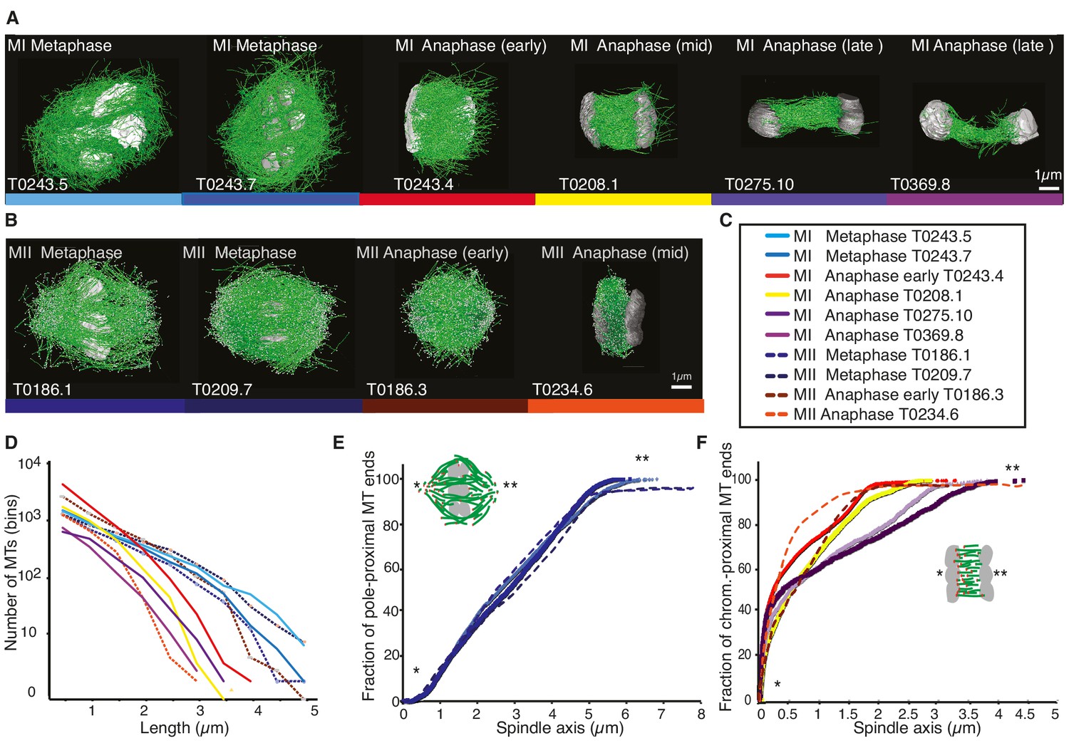
Three-dimensional organization of microtubules in meiosis I and II.
(A) Three-dimensional models showing full reconstruction of microtubules at different stages of wild-type meiosis I. The different stages from metaphase to late anaphase are indicated. Microtubules are shown in green, chromosomes in gray. An individual color is assigned to each dataset. The anaphase datasets are oriented with the cortical side being left, cytoplasmic right. (B) Like (A) but three-dimensional models showing full reconstruction of microtubules at different stages of wild-type meiosis II. (C) Legend for the different datasets plotted in (D–F). (D) Length distribution of microtubules composing the different spindles. Bin size 250 nm. (E) Cumulative distance function of the pole-proximal microtubule endpoints in metaphase of meiosis I and II. The position of the spindle poles in the schematic drawing and the datasets is indicated (stars). (F) Cumulative distance function of the chromosome-proximal microtubule endpoints in anaphase. The position of the poles is indicated (stars).
Figure 1—video 1
Visualization of spindle ultrastructure in meiosis I at mid anaphase.
This movie (corresponding to Figure 1A; anaphase, mid) shows a close up-view of the microtubule organization at mid anaphase. Microtubules are visualized in green, chromosomes in grey.
Figure 1—video 2
Visualization of spindle ultrastructure in meiosis I at late anaphase.
This movie (corresponding to Figure 1A; anaphase, late #1) shows a close up-view of the microtubule organization at late anaphase. Microtubules are visualized in green, chromosomes in grey.
Figure 2
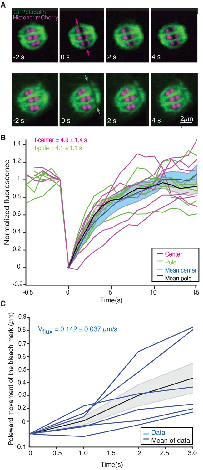
Microtubule dynamics during metaphase of meiosis I.
(A) Light microscope images of spindles in meiosis I prior to and after photobleaching at the spindle center (top row, red arrows) and close to the spindle pole (bottom row, green arrows). The bleaching of the sample (t = 0) and the frame rate is indicated. (B) Plot of the recovery of the bleach mark over time at the center (magenta, mean values given in blue) and pole (green, mean values given in black) for different datasets. The recovery times for the datasets are shown in the plot. (C) Plot showing the poleward motion of the bleach mark at the spindle pole over time for different datasets (blue). The mean is indicated in black.
Figure 3 with 1 supplement
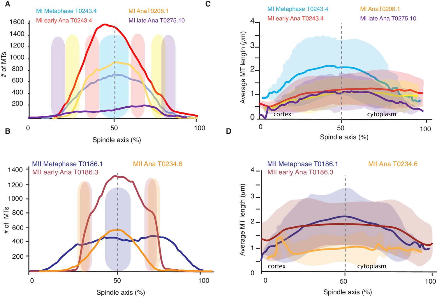
Analysis of microtubule number and length along the spindle axis.
(A) Plot of the number of microtubules at different positions (100 nm steps) along the spindle axis for four different datasets in metaphase, early anaphase, and mid and late anaphase in meiosis I. The approximate position of chromosomes for each dataset is indicated by the colored ovals. The datasets are oriented with ‘0’ being at the cortical side. Datasets are aligned with the center of the spindle located at 50%. (B) Same plot as in (A) but for meiosis II. (C) Plot of the average microtubule length at different positions (100 nm steps) along the spindle axis for four different datasets in metaphase, early anaphase, and mid and late anaphase. Shaded color indicates the standard deviation, datasets are oriented with ‘0’ being at the cortical side. Datasets are aligned with the center of the spindle located at 50%. (D) Same plot as in (C) but for meiosis II.
Figure 3—video 1
Visualization of spindle ultrastructure in meiosis I at late anaphase.
This movie (corresponding to Figure 3A; anaphase, late #2) shows a close up-view of the microtubule organization at late anaphase. Microtubules are visualized in green, chromosomes in grey.
Figure 4

Analysis of microtubule number according to their length along the spindle axis.
(A–G) Tomographic reconstructions of meiotic spindles in meiosis I and II showing microtubules of different length. Microtubules with length ≤ 500 nm are magenta, microtubules between 0.51 and 1 µm are green, and microtubules between 1.1 and 1.5 µm are yellow. Chromosomes are gray, spindles are oriented with the cortical site to the left. Scale bar 1 µm. (H–N) Plots showing the number of microtubules according to their length along the spindle axis for the datasets shown in (A–G). Dark line shows the number of microtubules ≤ 500 nm, medium gray line microtubules between 0.5 and 1 µm, and light gray lines microtubules between 1 and 1.5 µm. The approximate position of chromosomes is indicated by gray outlines.
Figure 5

Processes determining microtubule (MT) length distributions.
Our model considers MT turnover with a rate r and cutting with a rate κ. α is the stability of cutting-generated MT plus ends.
Figure 6 with 1 supplement
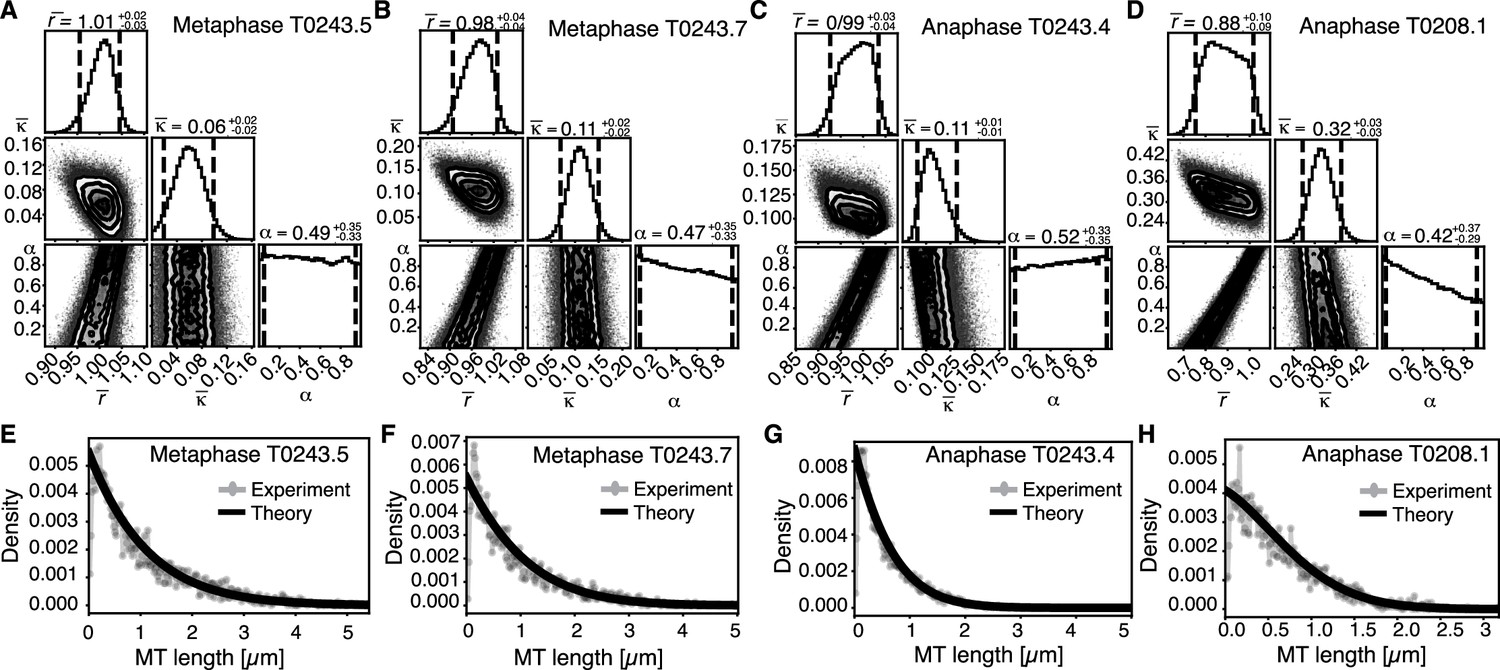
Inference of model parameters in metaphase and anaphase spindles of meiosis I.
(A) Likelihood distribution of model parameters determined by Markov Chain Monte Carlo (MCMC) for metaphase T0243.5. The top boxes show the totally marginalized distribution of parameters, with dashed lines delimiting the 95% confidence interval. Surface plots show cuts through the likelihood distributions, marginalized onto 2D subspaces. Lines are contour lines, dots indicate MCMC samples. (B) Same as in (A) but for the metaphase T0243.7 dataset. (C) Same as in (A) but for the early anaphase T0243.4 dataset. (D) Same as in (A) but for the mid anaphase T0208.1 dataset. (E–H) Comparison of experimentally determined length distribution of microtubules (dots) to the prediction of the highest likelihood model (solid line) for metaphase T0243.5 (E), metaphase T0243.7 (F), early anaphase T0243.4 (G), and mid anaphase T0208.1 (H). Plots for meiosis II can be found in Figure 6—figure supplement 1.
Figure 6—figure supplement 1
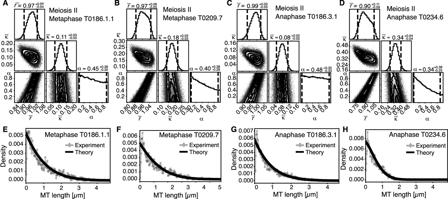
Inference of model parameters in metaphase and anaphase spindles of meiosis II.
(A) Likelihood distribution of model parameters determined by Markov Chain Monte Carlo (MCMC) for meiosis II metaphase T0186.1.1. The top boxes show the totally marginalized distribution of parameters, with dashed lines delimiting the 95% confidence interval. Surface plots show cuts through the likelihood distributions, marginalized onto 2D subspaces. Lines are contour lines, dots indicate MCMC samples. (B) Same as in (A) but for the metaphase T0209.7 dataset. (C) Same as in (A) but for the early anaphase T0186.3.1 dataset. (D) Same as in (A) but for the mid anaphase T0234.6 dataset. (E–H) Comparison of experimentally determined length distribution of microtubules (dots) to the prediction of the highest likelihood model (solid line) for metaphase T0186.1.1 (E), metaphase T0209.7 (F), early anaphase 186.3.1 (G), and mid anaphase T0234.6 (H).
Figure 7

Analysis of microtubule length distributions within 150 nm of the chromosomes.
(A) Tomographic reconstructions of meiotic spindles in meiosis I from metaphase to anaphase. The reconstructions show microtubules located with and end or lattice point within 150 nm from the chromosome surface in magenta and microtubules located further away in green. Chromosomes are gray. Scale bar 1 µm. (B) Same as (A) but for spindles in meiosis II. (C) Plot of the length distribution of microtubules in respect to their distance from the chromosomes for metaphase spindles in meiosis I and II. Red lines show microtubules located within 150 nm from the chromosomes, blue lines show microtubules further away. Bin size 250 nm. (D) Similar to the plot in (C) but for anaphase spindles in meiosis I and II.
Figure 8 with 2 supplements
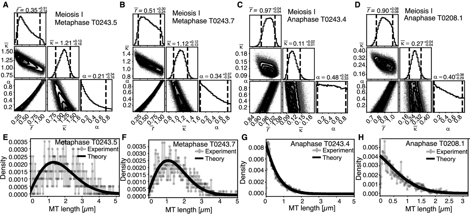
Selective inference model parameters in metaphase and anaphase spindles in meiosis I for microtubules located within 150 nm of the chromosomes.
(A) Likelihood distribution of model parameters determined by Markov Chain Monte Carlo (MCMC) for microtubules within 150 nm distance from the chromosomes in metaphase T0243.5 meiosis I. The top boxes show the totally marginalized distribution of parameters, with dashed lines delimiting the 95% confidence interval. Surface plots show cuts through the likelihood distributions, marginalized onto 2D subspaces. Lines are contour lines, dots indicate MCMC samples. (B) Same as in (A) but for meiosis I metaphase T0243.7 dataset. (C) Same as in (A) but for meiosis I T0243.3 early anaphase dataset. (D) Same as in (A) but for the meiosis I mid anaphase T0208.1 dataset (E–H) Comparison of experimentally determined length distributions of microtubules located within 150 nm from the chromosome surface (dots) to the prediction of the highest likelihood model (solid line) for meiosis I metaphase T0243.5 (E), meiosis I metaphase T0243.7 (F), meiosis I early anaphase T0234.4 (G), and meiosis I mid anaphase T0208.1 (H). Plots for meiosis II can be found in Figure 8—figure supplement 1, and plots for microtubules further away than 150 nm can be found in Figure 8—figure supplement 2.
Figure 8—figure supplement 1
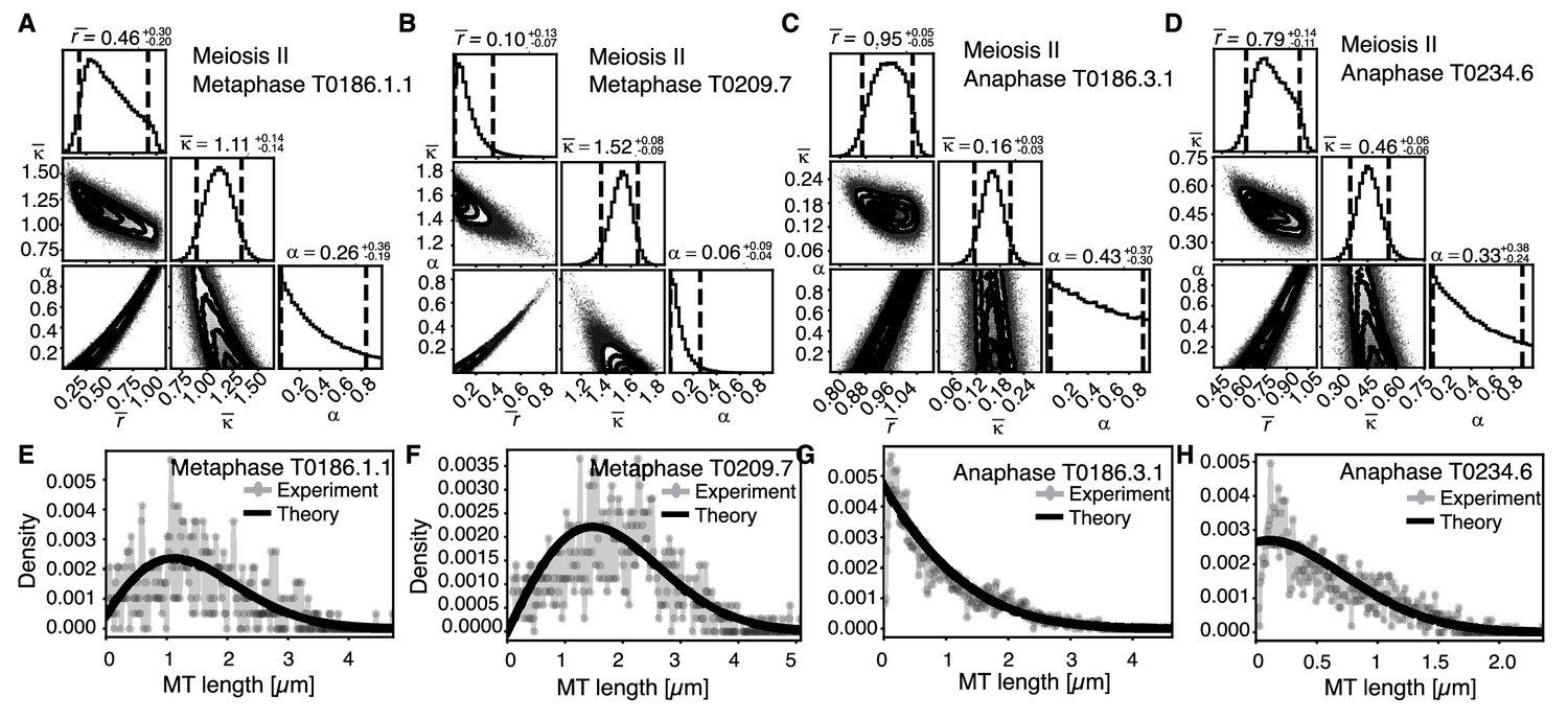
Selective inference model parameters in meiosis II metaphase and anaphase spindles for microtubules located within 150 nm of the chromosomes.
(A) Likelihood distribution of model parameters determined by Markov Chain Monte Carlo (MCMC) for microtubules within 150 nm distance from the chromosomes in meiosis II metaphase T0186.1.1. The top boxes show the totally marginalized distribution of parameters, with dashed lines delimiting the 95% confidence interval. Surface plots show cuts through the likelihood distributions, marginalized onto 2D subspaces. Lines are contour lines, dots indicate MCMC samples. (B) Same as in (A) but for the metaphase T0209.7 dataset. (C) Same as in (A) but for the early anaphase T0186.3.1 dataset. (D) Same as in (A) but for the mid anaphase T0234.6 dataset. (E–H) Comparison of experimentally determined length distribution of microtubules (dots) to the prediction of the highest likelihood model (solid line) for metaphase T0186.1.1 (E), metaphase T0209.7 (F), early anaphase T0186.3.1 (G), and mid anaphase T0234.6 (H).
Figure 8—figure supplement 2
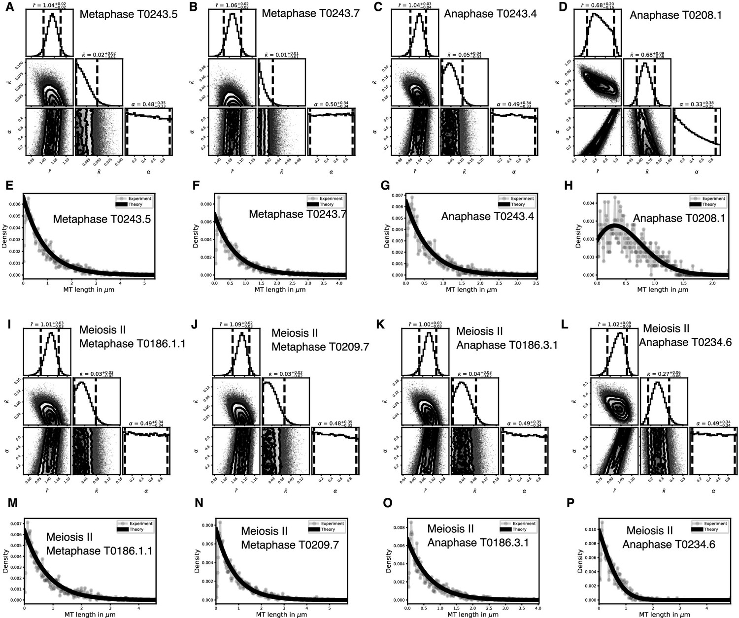
Selective inference model parameters in metaphase and anaphase spindles for microtubules located further than 150 nm from the chromosomes in meiosis I and II.
(A) Likelihood distribution of model parameters determined by Markov Chain Monte Carlo (MCMC) for meiosis II metaphase T0186.1.1. The top boxes show the totally marginalized distribution of parameters, with dashed lines delimiting the 95% confidence interval. Surface plots show cuts through the likelihood distributions, marginalized onto 2D subspaces. Lines are contour lines, dots indicate MCMC samples. (B) Same as in (A) but for the metaphase T0209.7 dataset. (C) Same as in (A) but for the early anaphase T0186.3.1 dataset. (D) Same as in (A) but for the mid anaphase T0234.6 dataset. (E–H) Comparison of experimentally determined length distribution of microtubules (dots) to the prediction of the highest likelihood model (solid line) for metaphase T0186.1.1 (E), metaphase T0209.7 (F), early 50 nm distance from the chromosomes in meiosis II metaphase T0186.1.1. The top boxes show the totally marginalized distribution of parameters, with dashed lines delimiting the 95% confidence interval. Surface plots show cuts through the likelihood distributions, marginalized onto 2D subspaces. Lines are contour lines, dots indicate MCMC samples. (J) Same as in (I) but for the metaphase T0209.7 dataset. (K) Same as in (I) but for the early anaphase T0186.3.1 dataset. (L) Same as in (I) but for the mid anaphase T0234.6 dataset. (M–P) Comparison of experimentally determined length distribution of microtubules (dots) to the prediction of the highest likelihood model (solid line) for metaphase T0186.1.1 (M), metaphase T0209.7 (N), early anaphase T0186.3.1 (O), and mid anaphase T0234.6 (P).
Figure 9
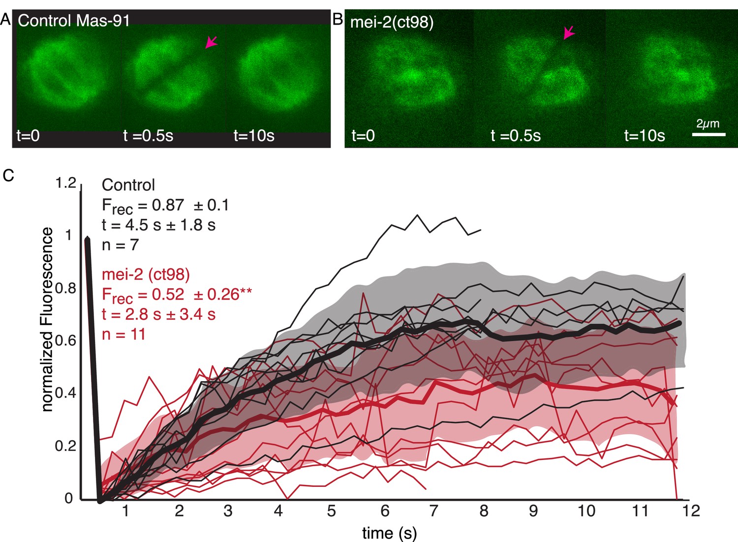
Microtubule turnover during metaphase of meiosis I in mei-2(ct98) embryos.
(A) Light microscope images of spindles in control embryos in meiosis I prior to and after photobleaching at the spindle center (red arrow). The time points are indicated. (B) Light microscope images of spindles in meiosis I in the katanin mei-2(ct98) mutant prior to and after photobleaching at the spindle center (red arrow). The time points are indicated. Scale bar 2 µm. (C) Plot of the recovery of the bleach mark over time in control embryos (black) and mei-2 (ct98) (red) for different datasets. Mean values are indicated by thick lines, the shaded region corresponds to the standard deviation. The fraction of recovery (Frec) and recovery times for the datasets are shown in the plot.
Figure 10
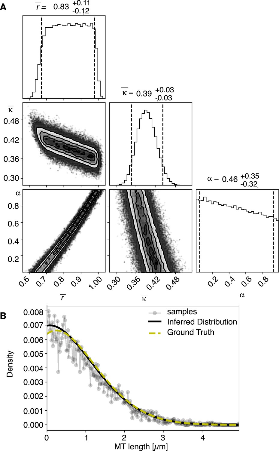
Results of inference versus ground truths on artificial data: case with cutting.
(A) Likelihood distribution of model parameters determined by Markov Chain Monte Carlo (MCMC) for microtubules assuming cutting of microtubules. The top boxes show the totally marginalized distribution of parameters, with dashed lines delimiting the 95% confidence interval. Surface plots show cuts through the likelihood distributions, marginalized onto 2D subspaces. Lines are contour lines, dots indicate MCMC samples. (B) Comparison of experimentally determined length distribution of microtubules (gray) to the prediction of the highest likelihood model (black) and the ground truth (green).
Figure 11
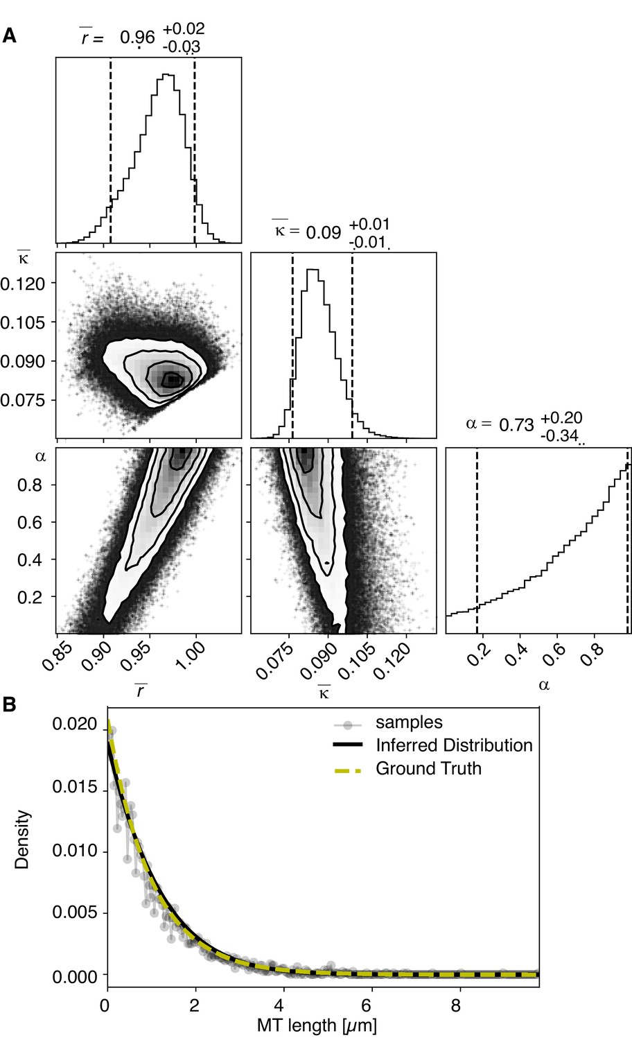
Results of inference versus ground truths on artificial data: case without cutting.
(A) Likelihood distribution of model parameters determined by Markov Chain Monte Carlo (MCMC) for microtubules assuming microtubules are not cut. The top boxes show the totally marginalized distribution of parameters, with dashed lines delimiting the 95% confidence interval. Surface plots show cuts through the likelihood distributions, marginalized onto 2D subspaces. Lines are contour lines, dots indicate MCMC samples. (B) Comparison of experimentally determined length distribution of microtubules (gray) to the prediction of the highest likelihood model (black) and the ground truth (green).
Videos
Video 1
FRAP during metaphase in Meiosis I in control embryo.
Movie of a FRAP experiment during metaphase in meiosis I of C. elegans expressing GFP tubulin and mCherry Histone. A small stripe is bleached next to the Chromosomes (right side) and the motion and recovery of the stripe over time are analyzed. Framerate 1fps.
Video 2
FRAP during metaphase in Meiosis I in mei-2(ct98) embryo.
Movie of a FRAP experiment during metaphase in meiosis I of C. elegans mei-2(ct98) expressing GFP tubulin and histone cherry. Only the tubulin channel is shown. A small stripe is bleached in the center of the spindle and recovery of the stripe over time is analyzed. Framerate five fps.
Tables
Table 1
Summary of quantifications of tomographic data for meiosis I.
The spindle length, the total number of microtubules, the number of microtubules within 150 nm from the chromosome surface, the average microtubule length, the maximum length of microtubules, the total length of all microtubules (net polymer length) in the spindle, and the dimension of the tomogram and spindle dimensions are shown for each tomographic dataset. The * labels newly generated datasets. MTs: microtubules.
| Meiosis I | Metaphase T0243.5 | Metaphase T0243.7* | Early anaphase T0243.4 | Mid anaphase T0208.1 | Late anaphase T0275.10* | Late anaphase T0369.9* |
|---|---|---|---|---|---|---|
| Spindle length (µm) | 5 | 5.4 | 3.1 | 2.7 | 4.5 | 5.1 |
| Number of MTs | 3662 | 3812 | 7011 | 3317 | 1511 | 1306 |
| MT within 150 nm | 500 | 920 | 5361 | 2334 | 875 | 699 |
| Average MT length (µm) | 0.91 ± 0.08 | 1.04 ± 0.93 | 0.58 ± 0.52 | 0.62 ± 0.49 | 0.74 ± 0.54 | 0.55 ± 0.45 |
| Max. MT length (µm) | 5 | 5.4 | 5 | 3.2 | 4.2 | 2.9 |
| Net polymer length (µm) | 3338 | 3961 | 4045 | 2061 | 1111 | 724 |
| Tomogram dimensions (µm) | 9.1 × 9.7 × 3.8 | 9.1 × 8 × 2.1 | 5 × 5.9 × 2.8 | 5.5 × 6.6 × 4.1 | 7.5 × 5.6 × 2.6 | 6.9 × 5.5 × 2.6 |
| Spindle dimensions (µm) | 5 × 8 × 3.9 | 5.4 × 5.6 × 2.1 | 3.1 × 4.3 × 2.6 | 2.7 × 3 × 2.5 | 4.5 × 1.2 × 1 | 5.1 × 1.4 × 0.8 |
Table 2
Summary of quantifications of tomographic data for meiosis II.
The spindle length, the total number of microtubules, the number of microtubules within 150 nm from the chromosome surface, the average microtubule length, the maximum length of microtubules, the total length of all microtubules (net polymer length) in the spindle, and the dimension of the tomogram and spindle dimensions are shown for each tomographic dataset. The * labels newly generated datasets. MTs: microtubules.
| Meiosis II | Metaphase T0186.1* | Metaphase T0209.7* | Early anaphase T0186.3* | Mid anaphase T0234.6* |
|---|---|---|---|---|
| Spindle length (µm) | 5.9 | 5.8 | 4.0 | 2.5 |
| Number of MTs | 3013 | 3808 | 5572 | 2246 |
| MT within 150 nm | 484 | 887 | 3298 | 1359 |
| Average MT length (µm) | 0.88 ± 0.78 | 1.11 ± 0.92 | 0.90 ± 0.79 | 0.57 ± 0.49 |
| Max. MT length (µm) | 4.7 | 5.8 | 4.6 | 2.8 |
| Net polymer length (µm) | 2693 | 4237 | 4512 | 236 |
| Tomogram dimensions (µm) | 8.6 × 9.8 × 3.3 | 11 × 5.5 × 2.8 | 5.6 × 6.9 × 2.7 | 9 × 6.2 × 3.3 |
| Spindle dimensions | 5.9 × 5.8 × 3.8 | 5.8 × 4.1 × 3.1 | 4 × 4.1 × 3.3 | 2.5 × 3.7 × 2.8 |
Key resources table
| Reagent type (species) or resource | Designation | Source or reference | Identifiers | Additional information |
|---|---|---|---|---|
| Strain, strain background (Caenorhabditis elegans) | MAS-91 | Martin Srayko (U of Alberta) | (unc-119(ed3) III; ItIs37[pAA64; pie-1::mCherry::HIS58]; ruIs57[pie-1::GFP::tubulin+unc-119(+)]) | Expresses GFP tubulin and histone mCherry in the C. elegans embryo |
| Strain, strain background (C. elegans) | SA250 | CGC | (tjIs54 [pie-1p::GFP::tbb-2+pie-1p::2xmCherry::tbg-1+unc-119(+)]; tjIs57 [pie-1p::mCherry::his-48+unc-119(+)]) | Expresses GFP tubulin and histone mCherry in the C. elegans embryo |
| Strain, strain background (C. elegans) | FM13 | Frank McNally (UC Davis) | (mei-2(ct98) I; ruls57 [pAZ147: pie-1promoter::tubulin::GFP; unc-119(+)]; itls37 [unc-119(+) pie-1promoter::mCherry::H2B]; him-8(e1489) IV) | Mei-2(ct98) Katanin mutant |
| Software, algorithm | MATLAB, MathWorks | MATLAB R2020a, | Including image processing toolbox | |
| Software, algorithm | IMOD, Boulder Labs, CO | http://bio3d.colorado.edu/imod | ||
| Software, algorithm | Amira, FEI | AmiraZibEdition |
Additional files
Download links
A two-part list of links to download the article, or parts of the article, in various formats.
Downloads (link to download the article as PDF)
Open citations (links to open the citations from this article in various online reference manager services)
Cite this article (links to download the citations from this article in formats compatible with various reference manager tools)
Microtubule reorganization during female meiosis in C. elegans
eLife 10:e58903.
https://doi.org/10.7554/eLife.58903


