Full-length Plasmodium falciparum myosin A and essential light chain PfELC structures provide new anti-malarial targets
- Structural Motility, Institut Curie, Paris Université Sciences et Lettres, Sorbonne Université, CNRS UMR144, France
- Department of Molecular Physiology and Biophysics, University of Vermont, United States
- Laboratoire de Biologie des Ligneux et des Grandes Cultures (LBLGC), Université d’Orléans, INRAE, USC1328, France
- Department of Life Sciences, Imperial College London, South Kensington, United Kingdom
Figures
Figure 1 with 4 supplements
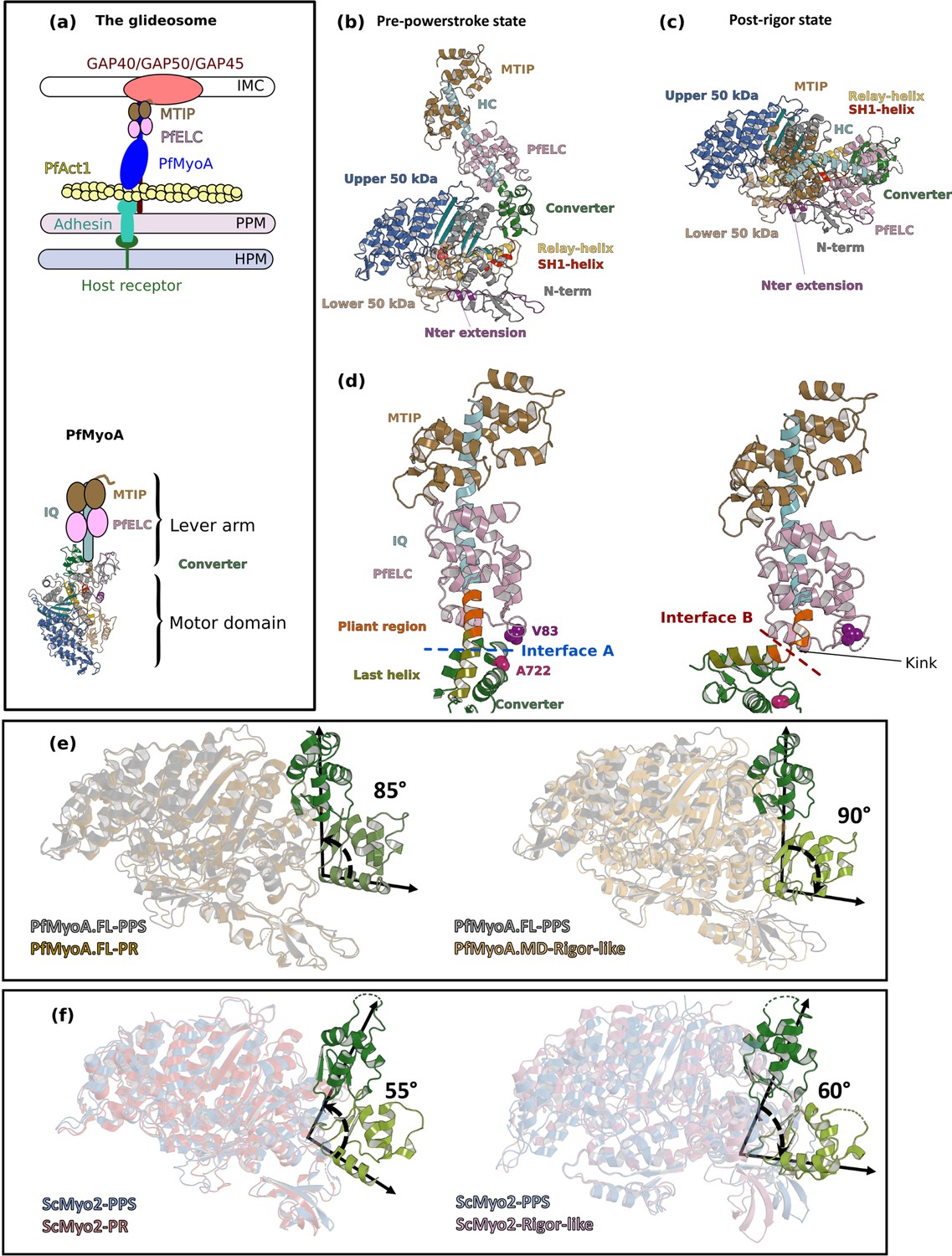
Crystal structures of PfMyoA in the Post-rigor (PR) and the Pre-Powerstroke (PPS) states.
(a) (Left) The PfMyoA motor is located in the intermembrane space of the parasite. PfMyoA (blue) binds two light chains, PfELC and myosin tail interacting protein (MTIP). MTIP connects the motor to the glideosome-associated proteins (GAP) complex, which is anchored in the inner membrane complex (IMC). PfMyoA cyclically interacts with PfAct1 filaments, which are bound to adhesins from the parasite plasma membrane (PPM); these adhesins also bind receptors from the host cell plasma membrane (HPM). The displacement of PfAct1 filaments by PfMyoA drives parasite gliding motility. (Right) The crystal structure of the motor domain of PfMyoA has been solved (Robert-Paganin et al., 2019), but the lever arm structure was not known. (b,c) Overall structures of the full-length PfMyoA motor in the PPS and PR states, displayed so that their N-terminal subdomains adopt a similar orientation. As expected, the orientation of the converter and lever arm differs in these two states. (d) The lever arm has been built in these two states of the motor, revealing the structure of the two bound light chains, PfELC and MTIP, displayed here in a similar orientation. The kink in the lever arm helix at the end of the converter (pliant region in orange; last helix of the converter in deep olive green) induces different converter/PfELC interfaces in the PPS (interface A, left) compared to the PR state (interface B, right). To illustrate that the two interfaces are different, two reporter residues are displayed as spheres, A722 from the converter and V83 from PfELC. These residues are the part of interface A but not the part of interface B. (e) and (f) represents the recovery stroke (left) and the powerstroke (right) for PfMyoA and scallop myosin 2 (ScMyo2), respectively. Structures of ScMyo2 used: PR (PDB code 1S5G); PPS (PDB code 1QVI).
Figure 1—figure supplement 1
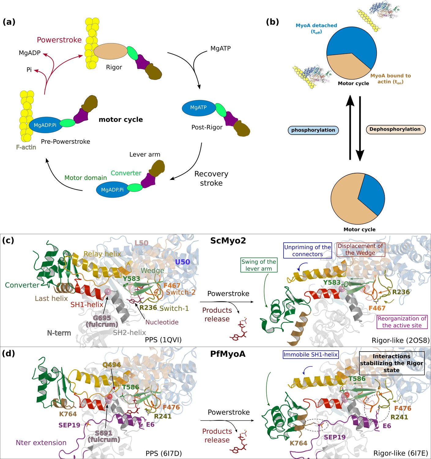
The atypical and tunable mechanical cycle of PfMyoA.
(a) Motor cycle of myosin motors. The nucleotide free state, strongly bound to actin, is called rigor. Binding of ATP in the rigor state detaches the head from actin. Upon detachment, the motor first populates the post-rigor state (PR) with ATP bound. Isomerization toward the pre-powerstroke state (PPS) allows ATP hydrolysis. This state binds weakly to actin. The sequential release of the products of hydrolysis drives the lever arm swing and thus the powerstroke, which generates force. Detachment of the motor upon ATP binding starts a new cycle. (b) PfMyoA properties are tuned by a phosphorylation in the N-terminal extension of the motor domain (SEP19). When the motor is phosphorylated, it moves actin with a high velocity spending a short fraction of the cycle strongly bound to actin. When the motor is dephosphorylated, it produces more force at the expense of speed. (c) and (d) show the mechanism of force production in scallop myosin 2 (ScMyo2) and PfMyoA, respectively. In ScMyo2, the mobility of the SH1-helix is a key element for the mechanism driving the powerstroke of most myosins and requires the presence of a conserved glycine (G695), the so-called fulcrum, at the basis of the SH1-helix (Kinose et al., 1996; Kad et al., 2007; Preller et al., 2011). In PfMyoA, the SH1-helix is immobile, due to the presence of a serine at the fulcrum (S691). The lack of mobility of the fulcrum is compensated by a phosphorylatable N-terminal extension (SEP19) and sequence adaptations in the connector.
Figure 1—figure supplement 2

The crystal structure of the PfMyoA-PR state displays a kink at the pliant region.
(a) Overall structure of PfMyoA•ΔNter-PR. (b) PfMyoA•ΔNter-PR and PfMyoA•FL-PR superimpose perfectly (rmsd 0.330 Å), indicating that the deletion does not change or alter the protein fold. (c) The PR state of PfMyoA•FL displays a kink in the lever arm at the pliant region (orange). The converter thus becomes far from the α5* and α5*’ helices, which are destabilized (not modeled since no density is indicated in the electron density map). (d) Crystal packing shows that the kinked lever arm is involved in a large surface of the crystal packing. (e), (f), (g) Small-angle X-ray scattering experiment investigating the conformation of PfMyoA in solution. (e) When the motor is bound to ADP and Pi analogs, the theoretical curve computed from the PfMyoA•FL-PPS structure (chain A) fits well to the SAXS experimental curve (χ2 = 3.32). (f) When the motor is bound to MgADP, the experimental curve fits poorly to the theoretical curve from the kinked PfMyoA•FL-PR crystal structure (χ2 = 302), (g) The SAXS experimental curve fits better to the theoretical curve obtained from a model of the PR state in which no kink occurs at the end of the converter (open conformation) (χ2 = 19.2). (h) A fit of the theoretical curve in the PR condition with the software Oligomer (Ryan et al., 2020). The fit has been performed with the closed PfMyoA•FL-PR structure obtained from the crystal with a kink at the pliant region (interface A) and a computed open PfMyoA•FL-PR structure (interface B from the PfMyoA•FL-PPS structure) (see Figure 1). Calculations predict 98% of the sample in the open conformation (χ2 = 8.69).
Figure 1—figure supplement 3

Electron density in the PfMyoA structures.
For all structures, the lever arm and the connectors are displayed, and the 2Fo-Fc map is shown, contoured at 1.0 σ. (a) PfMyoA•FL-PR at 2.5 Å resolution. (b) PfMyoA•FL-PPS at 3.9 Å resolution. (c) PfMyoA•ΔNter-PR at 3.3 Å resolution.
Figure 1—figure supplement 4
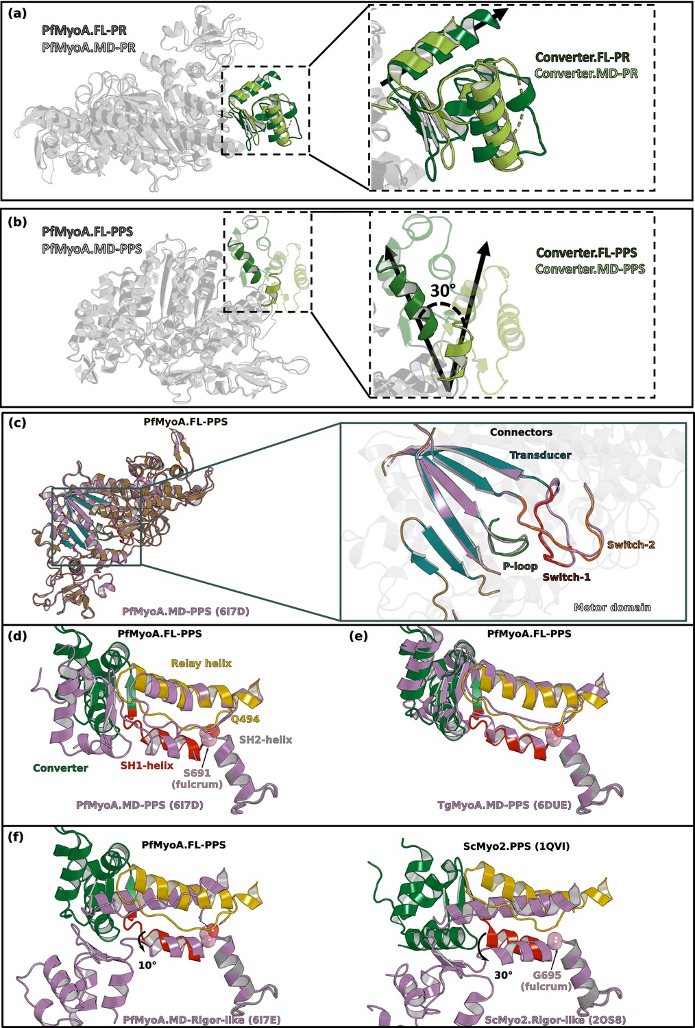
The orientation of the lever arm of PfMyoA in PPS differs in the structures of the MD and of the FL.
(a) The orientation of the converter in the post-rigor state (PR) of PfMyoA is identical in the structures of the full-length (FL) and of the motor domain (MD) constructs (PDB code 6I7D chain A). (b) In the pre-powerstroke state (PPS), the lever arm is 30° more primed in the FL structure compared to that found in the MD structure (PDB code 6I7E). (c) Superimposition on the N-terminal subdomain of PfMyoA.FL-PPS and PfMyoA•MD-PPS. On the left, overall view showing that the conformation of the motor domain is similar for the two structures. On the right, zoom on the transducer and on the connectors of the active site (P-loop, Switch-1 and Switch-2) show that the conformation of these elements, which is characteristic of the state, is highly similar. On the following panels, all the structures are superimposed on the SH2-helix. (d) The positions of both the relay-helix and the converter vary between the FL and the MD constructs. Since the SH1-helix was reported to be immobile in PfMyoA (Frénal et al., 2017), its position only slightly differs between the two constructs. (e) The priming of PfMyoA•FL-PPS is identical to the priming of TgMyoA•MD-PPS (PDB code 6DUE). The communication described between the SH1- and the relay helices (polar bond between S691 and Q494) (Frénal et al., 2017) is similar as well as the orientation of the lever arm. (f) Comparison of the position of the connectors between the PPS and the rigor-like states in PfMyoA (Left), and ScMyo2 (Right). The priming described in the PfMyoA•FL-PPS structure indicates that the SH1-helix remains mostly immobile: this connector is only rotated 10° during the powerstroke. This rotation is of smaller amplitude compared to that of conventional myosins such as ScMyo2 (~30°).
Figure 2

Sequence adaptations tune distinct transitions of the cycle.
(a) Location and function of three mutated residues. (b) Speed distributions from representative in vitro motility assays. Supplementary file 1b shows values from additional experiments. (c) ADPrelease rates from acto-PfMyoA. WT data are from Robert-Paganin et al., 2019. Data for LRA (three experiments, two protein preparations); E6R (three experiments, three protein preparations); T586F (three experiments, two protein preparations); S691G (four experiments, three protein preparations). Values, mean ± SD. (d) Correlation of ADP -release rates and in vitro motility speed. (e) Actin-activated ATPase activity. WT data are from Robert-Paganin et al., 2019 . Data from at least two protein preparations and two experiments for each construct were fitted to the Michaelis-Menten equation. Error, SE of the fit. (f) Ensemble force measurements using a utrophin-based loaded in vitro motility assay. A myosin that produces more force requires higher utrophin concentrations to slow motion: E6R, 4.02 ± 0.31 nM; T586F, 2.38 ± 0.18 nM; S691G, 1.99 ± 0.19 nM; WT, 1.40 ± 0.08 nM. WT data are from Robert-Paganin et al., 2019. Error, SE of the fit. Data from two protein preparations and three experiments for each mutant construct. Figure 6—figure supplement 1d shows additional data with an expanded x-axis. Skeletal actin was used for all experiments. Temperature, 30°C. See also Supplementary file 1b for values.
-
Figure 2—source data 1
Source data for kinetic experiments presented in Figure 2.
- https://cdn.elifesciences.org/articles/60581/elife-60581-fig2-data1-v1.xlsx
Figure 3 with 1 supplement
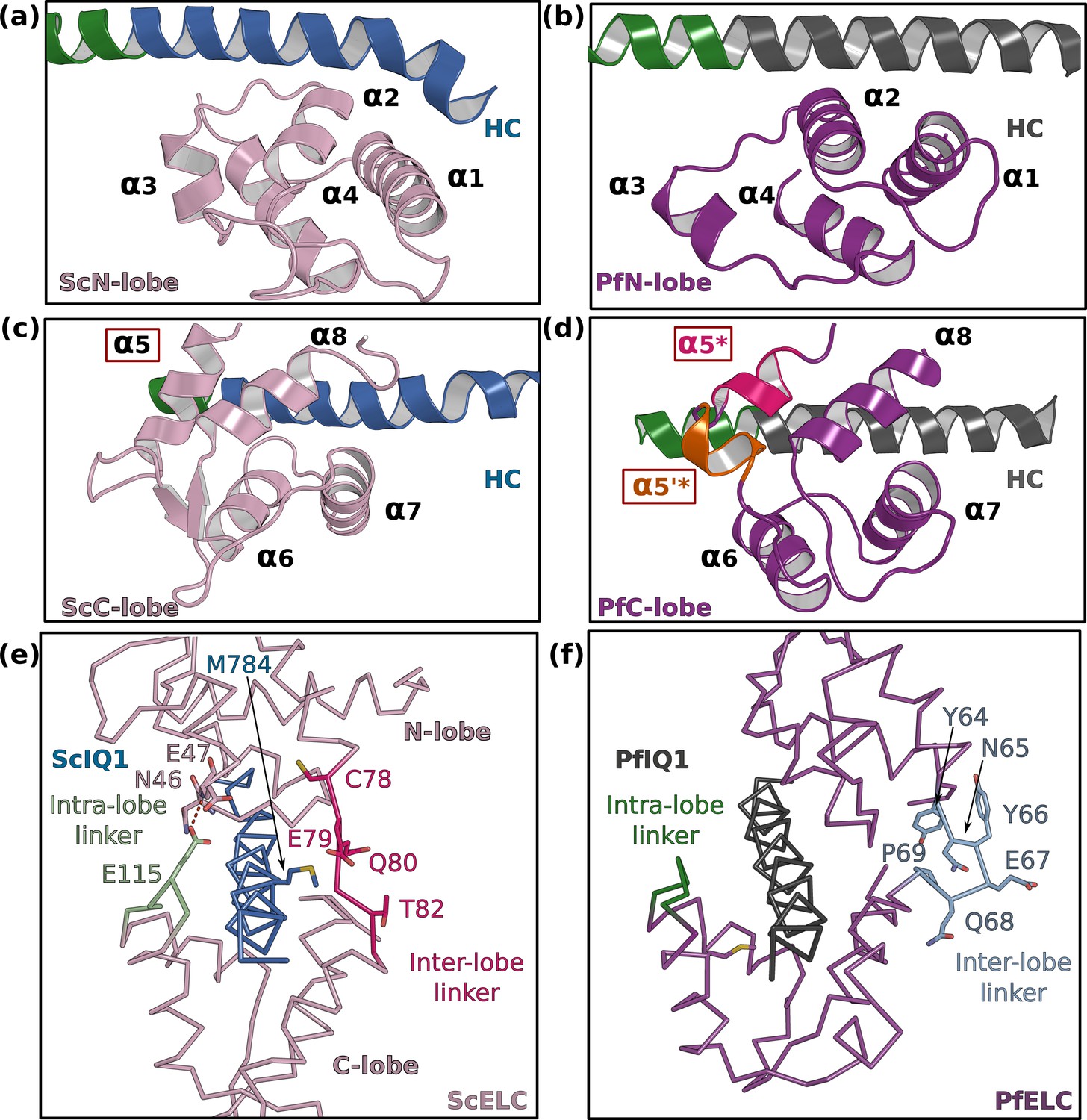
PfELC adopts an atypical fold.
(a) The N-lobe of scallop myosin 2 ELC (ScMyo2) is compared to (b) the N-lobe of PfELC. The two lobes are conserved in structure, and adopt a closed conformation. In contrast, the C-lobe of ScMyo2 ELC (c) and PfELC (d) differ. The most divergent feature is the much shorter α5* helix (comprised of only one turn) and the presence of the short α5’* helix in PfMyoA. (e) shows the elongated inter-lobe linker of ScELC (red) compared with (f) the kinked, hairpin-like inter-lobe linker of PfELC (light blue). The specific structure of the inter-lobe linker makes the PfELC structure more compact than canonical ELCs and no direct interaction can occur between the lobes in PfMyoA to encircle the heavy chain, contrary to what is seen in the case of ScMyo2.
Figure 3—figure supplement 1

MTIP bound to PfMyoA.
(a) Sequence alignment of PfMyoA IQ2 with conventional IQ motifs. Residues at consensus positions are colored in blue. (b) MTIP is bound to the heavy chain (HC) in a similar manner as a conventional ELC. Several residues from the consensus are conserved in PfIQ2. (c) Zoom on the specific contacts involved in the MTIP/PfMyoA recognition. (d, e) The recognition of the HC by MTIP is highly similar to the recognition of the HC by TgMLC1 (PDB 5VT9) and the residues involved in the apical salt bridge and the inter-lobe clamp (dotted lines) (Green et al., 2017) are conserved. (f) and (g) Interface between PfELC and MTIP. (f) The interface between PfELC and MTIP is hydrophobic and includes two aromatic residues (PfMTIPH150, PfMTIPW171) that maintain the relative positioning of the two light chains. A 132°angle occurs between the two HC helices that contain the PfIQ1 and PfIQ2 motifs. The kink is facilitated by the presence of a proline at the hinge (P802). (g) Alignment of the two molecules of the asymmetric unit in the PfMyoA•FL-PPS crystal structure. The hinge at the PfELC/MTIP interface is a restricted point of compliance since ~10° difference is found for the orientation of the PfIQ2 motif HC helices for these two molecules, when the structures are aligned using the PfIQ1 motif residues.
Figure 4 with 2 supplements
PfELC binds a degenerate IQ motif.
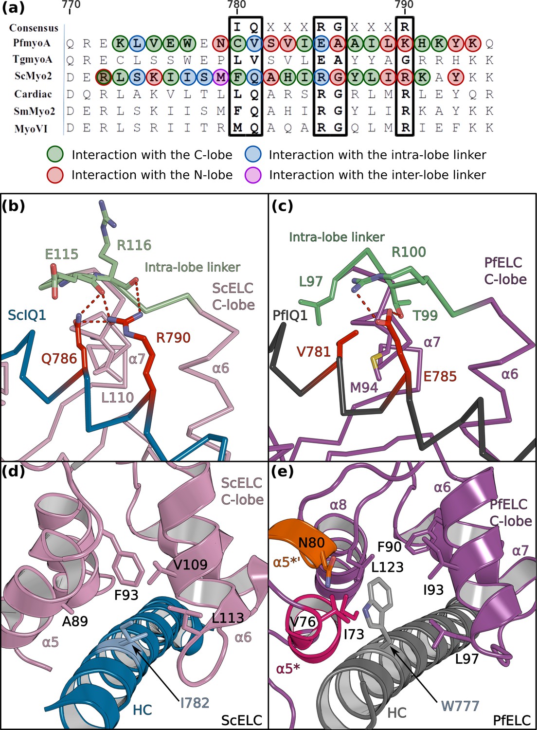
(a) Sequence alignment of PfMyoA IQ1 to the consensus IQ motif and IQ motifs from other myosins: MyoA from Toxoplasma gondii (TgmyoA); bay scallop (Argopecten irradians) myosin 2 (ScMyo2); human (Homo sapiens) β-cardiac myosin 2 (Cardiac); human smooth muscle myosin 2 (SmMyo2); human myosin 6 (MyoVI). Consensus residues are contoured by a black box. (b) The intra-lobe linker of the scallop C-lobe interacts with the HC consensus residues with polar contacts. (c) In contrast, the intra-lobe linker of the Pf C-lobe is predominantly bound to the HC with apolar contacts. (d,e) Intra-lobe interactions maintain the semi-open C-lobe. Specificity in the recognition of the PfELC occurs via the W777 residue in PfMyoA. (d) In conventional myosins such as ScMyo2, a small side chain (I782) is found at the equivalent position, contributing to few interactions within the semi-open lobe. (e) In PfMyoA the bulky Trp (W777) is sandwiched between the α5*, α5’* and α6 helices, increasing the hydrophobic interactions with the PfELC C-lobe.
Figure 4—figure supplement 1

Interaction between the IQ1 motif and the ELC.
(a) Sequence alignment of the IQ1 motif from ScMyo2 and PfMyoA. Residues interacting with the ELCs are contoured following the same color code as defined in Figure 4. (b, c) Two different orientations (180° rotation around the y axis) are shown to depict all residues involved in the IQ1 motif/ELC complex recognition, in order to compare (b) ScMyo2 and (c) PfMyoA Residues at consensus positions are labeled in red.(d) The tryptophan W777 stabilizes the α5* and α5’* helices. The left and the right panels show W777 and its environment in the structures of PfMyoA•FL-PPS and PfMyoA•FL-PR, respectively. Note the change in position of the W777 side chain due to its position at the kink of the pliant region. In PfMyoA•FL-PPS, W777 interacts with the α5* and α5’* helices stabilizing their structure. In PfMyoA•FL-PR, the interaction between W777 and the α5* and α5’* helices are lost due to the kink at the pliant region, and a loss of interaction of these helices with the Converter. These helices become disordered.
Figure 4—figure supplement 2

The converter/ELC interface differs in PfMyoA and in ScMyo2.
(a) The first IQ motif residues of PfMyoA starts one residue downstream to that of ScMyoA (PDB code 1QVI), resulting in a sequence shift in the pliant region and different orientation for the consensus IQ1 motif residues (balls). A difference in the kink at the pliant region accentuates the difference in position of the IQ1 residues in the two lever arms. (b, c) The C-lobe of PfELC and ScELC bound to the IQ1 motif are shown for comparison. The difference in the position of the HC consensus residues results in a different converter/ELC interface in (b) ScMyo2 compared with (c) PfMyoA (see Figure 6 for details of the interactions).
Figure 5
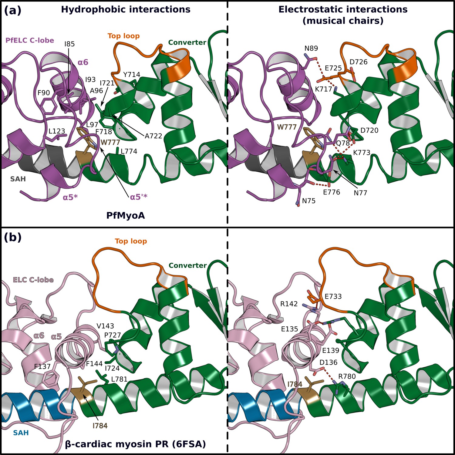
The atypical PfELC/Converter interface.
Comparison of the converter/ELC interface of (a) PfMyoA and (b) β-cardiac myosin. (Left), hydrophobic contacts are displayed. (Right), polar residues responsible for the contacts identified as ‘musical chairs’ in molecular dynamics experiments (Robert-Paganin et al., 2018) are labeled.
Figure 6 with 2 supplements

Interactions stabilizing the priming of the PfMyoA PPS state.
(a) Overall structure of PfMyoA•FL-PPS. The priming of the lever arm is stabilized by interactions between elements of the lever arm and the motor domain (boxed in black). (b) Zoom on the lever arm/motor domain interface. The residues involved in the interaction are labeled. Key residues that have been mutated to disrupt the interface (see d) are labeled red. (c,d) MD simulations comparing the WT and triple mutant R707A/E711A/Y714A. (c) The primed PPS state is stable during the entire duration of the simulation (320 ns). (d) In contrast, the priming is lost with the triple R707A/E711A/Y714A mutant and the position of the lever arm deviates by up to 54°.
Figure 6—figure supplement 1

Transient kinetics and genetic engineering of the parasite.
(a, e) Triple mutants that affect the atypical priming of PfMyoA. speed, ADP-release rate, and actin-activated ATPases for LRA (see also data presented in Figure 2) compared with the AAA mutant (LRA: R707L/E711R/Y714A; AAA: R707A/E711A/Y714A).(a) Speed distributions from a representative in vitro motility assay for LRA (1.19 ± 0.18 μm/s, n = 4092) and AAA (1.24 ± 0.24 μm/s, n = 3030). (b) ADP-release rates from acto-PfMyoA for LRA (117 ± 4 s−1) and AAA (122 ± 2 s−1). three experiments, one protein preparation of AAA. (c) Actin-activated ATPase activity for LRA (Vmax = 46.8 ± 1.0 s−1; Km = 9.1 ± 0.6 μM) and AAA (Vmax = 42.7 ± 0.9 s−1; Km = 12.3 ± 0.8 μM). Error, SE of the fit. two experiments, one protein preparation of AAA. (d) Ensemble force measurements using a utrophin-based loaded in vitro motility assay, showing more data and an expanded x-axis compared with the main Figure 2f. Temperature, 30°C. (e) Ensemble force measurement of FL PfMyoA with only MTIP light chain bound. A myosin that produces more force requires higher utrophin concentrations to slow motion. Minus PfELC: 1.57 ± 0.18 nM (red diamonds and solid red line fit); WT, 1.40 ± 0.08 nM; S19A, 2.42 ± 0.17 nM. WT and S19A data are from Frénal et al., 2017. Error, SE of the fit. Data for minus PfELC are from one protein preparation and two experiments. Skeletal actin was used for all experiments. Temperature, 30°C.
-
Figure 6—figure supplement 1—source data 1
Source data for kinetic experiments presented in Figure 6—figure supplement 1.
- https://cdn.elifesciences.org/articles/60581/elife-60581-fig6-figsupp1-data1-v1.xlsx
Figure 6—figure supplement 2
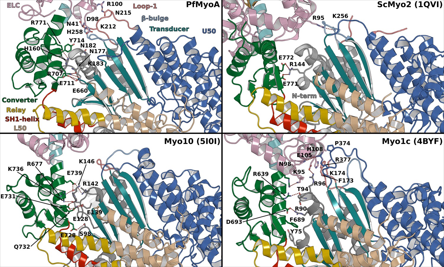
Interactions between the motor domain (MD) and the lever arm stabilizing the priming in PPS in different myosins.
Important interactions occur in PfMyoA between the converter and the N-terminal subdomain while the PfELC is involved in interactions with Loop1 and the β-bulge of the Transducer. In comparison, limited interactions occur in ScMyo2 consistent with smaller priming of the lever arm. Myo10 is another highly primed myosin but the interactions involve mainly the Converter with the N-terminal subdomain, without contribution from the Transducer. The priming of another highly primed PPS structure from Myo1c requires interaction of the CaM light chain with Loop1 and the HO-linker of the Transducer.
Figure 7 with 1 supplement
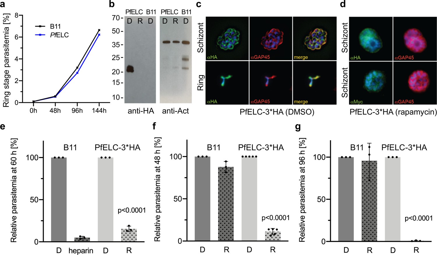
PfELC is essential for parasite invasion of the red blood cell.
(a) Growth curve comparing wildtype (B11) and PfELC-3xHA parasites over the course of three cycles indicates no detrimental effect of genetic modification in the pfelc locus. Mean ring-stage parasitemia is shown of two biological replicates as determined by flow cytometry. (b) Western blot analysis of parasite extracts separated by SDS-PAGE probed with anti-HA and anti-actin antibodies as a loading control. PfELC-3xHA runs at the expected MW of ~21 kDa in mock DMSO -treated samples (D) and the HA signal is lost upon treatment with rapamycin (R), indicating successful excision. (c–d) Representative immunofluorescence assays (IFAs) of schizont and ring-stage parasites co-labeled with the IMC marker GAP45. Peripheral staining is lost after treatment with rapamycin and a diffuse/punctate pattern is seen with anti-cMyc antibodies. (e) R-treated PfELC-3xHA parasites are significantly impaired in invading red blood cells as determined by flow cytometry analysis of ring-stage parasites over 60 hr, comparable to that seen with the non-specific inhibitor heparin. A small amount of residual invasion seen after 48 hr (f) disappears after 96 hr post-treatment (g) suggesting that the absence of PfELC results in complete ablation of invasion. D-treated parasites show no invasion defect. Parasitemias were normalized to D-treated for each line, bars show mean + / - S.D.
-
Figure 7—source data 1
Source data for parasitology experiments presented in Figure 7.
- https://cdn.elifesciences.org/articles/60581/elife-60581-fig7-data1-v1.xlsx
Figure 7—figure supplement 1

Genetic integration of LoxP Cre recombinase sites into the Pfelc gene of Plasmodium falciparum.
(a) Schematics of the targeting plasmid (pARL PfELCloxP), expected selection-linked integration (SLI) into the pfelc locus leading to C-terminally tagged PfELC 3xHA and the DiCre-mediated recombinase event resulting in the PfELC conditional KO (cKO). The recodonised version of the pfelc gene is shown as a red striped box, the 3x HA tag is depicted in blue, the T2A skip peptide in gray and the cMyc/FLAG tag in orange. The stop codon is indicated by an asterisk and primers used for genotyping are indicated by numbered arrows. (b) PCR analysis and confirmation of integration into the pfelc locus in transgenic PfELC 3x HA parasites as evidenced by loss of the wild-type band at ~1 kb (P1 and P2) and amplification of an ~1.2 kb (P1 and P3),~1.9 kb (P1 and P4) and ~1 kb (P5 and P2) product. Successful rapamycin-induced excision results in the expected loss of the ~1.2 kb band and size reduction of the ~1.9 kb product leading to PfELC cKO.
Videos
Video 1
Molecular dynamics performed on the structure of full-length (FL) PfMyoA in the PPS state (wild-type).
Zooms show the interface between PfELC (light pink) and MTIP, and the interface between the lever arm and the motor domain.
Video 2
Molecular dynamics performed on the structure of full-length (FL) PfMyoA in the PPS state (wild type).
Zoom at the interface between the converter and PfELC showing the musical chairs.
Video 3
Comparison of the dynamics on the structure of the molecular dynamics performed on the structures of full-length (FL) PfMyoA in the PPS state wild-type (WT) and of the in silico generated AAA mutant (R707A/E711A/Y714A).
Video 4
Comparison of the dynamics on the structure of the molecular dynamics performed on the structures of FL PfMyoA in the PPS state wild-type (WT) and of the in silico generated AAA mutant (R707A/E711A/Y714A).
Additional files
-
Supplementary file 1
Supplementary tables.
(a) Data collection and refinement statistics (molecular replacement). (b) Kinetic and motility parameters of PfMyoA mutants. (c) Dissociation of acto-PfMyoA by MgATP at 20°C.
- https://cdn.elifesciences.org/articles/60581/elife-60581-supp1-v1.docx
Download links
A two-part list of links to download the article, or parts of the article, in various formats.
Downloads (link to download the article as PDF)
Open citations (links to open the citations from this article in various online reference manager services)
Cite this article (links to download the citations from this article in formats compatible with various reference manager tools)
Full-length Plasmodium falciparum myosin A and essential light chain PfELC structures provide new anti-malarial targets
eLife 9:e60581.
https://doi.org/10.7554/eLife.60581


