The flagellar motor of Vibrio alginolyticus undergoes major structural remodeling during rotational switching
- Department of Microbial Pathogenesis, Yale School of Medicine, United States
- Microbial Sciences Institute, Yale University, United States
- Division of Biological Science, Graduate School of Science, Nagoya University, Furo-cho, Chikusa-ku, Japan
Figures
Figure 1 with 1 supplement
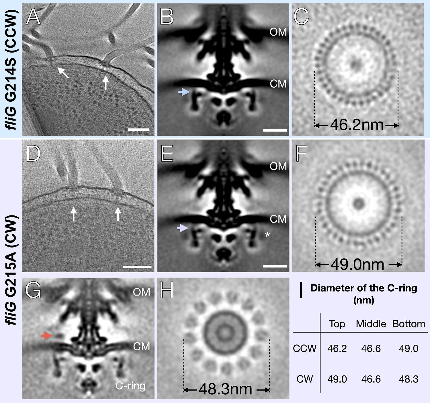
In situ structures of V. alginolyticus flagellum motor in CCW and CW rotation.
(A) A representative tomogram slice showing two motors in V. alginolyticus fliG G214S mutant (white arrow) Scale bar 100 nm. (B) A medial cross-section of the in situ flagellar motor structure. Scale bar 25 nm. (C) A perpendicular cross-section of the motor showing the top portion of the C-ring (blue arrow in B). (D) A representative tomogram slice of the CW-motor in V. alginolyticus fliG G215A CW-locked variant. (white arrow) Scale bar 100 nm. (E) A medial cross-section of the in situ flagellar motor structure. Scale bar 25 nm. (F) A perpendicular cross-section of the motor showing the top portion of the C-ring (purple arrow in E). (G) A medial cross-section of the flagellum motor with density for the stator (orange arrow). (H) A perpendicular cross-section of the motor showing the stator ring (orange arrow in G). (I) Diameters of the C-ring measured at the top, middle, and bottom from perpendicular cross-sections for both the CCW- and CW-motors. Abbreviations: outer membrane (OM), cytoplasmic membrane (CM).
Figure 1—figure supplement 1
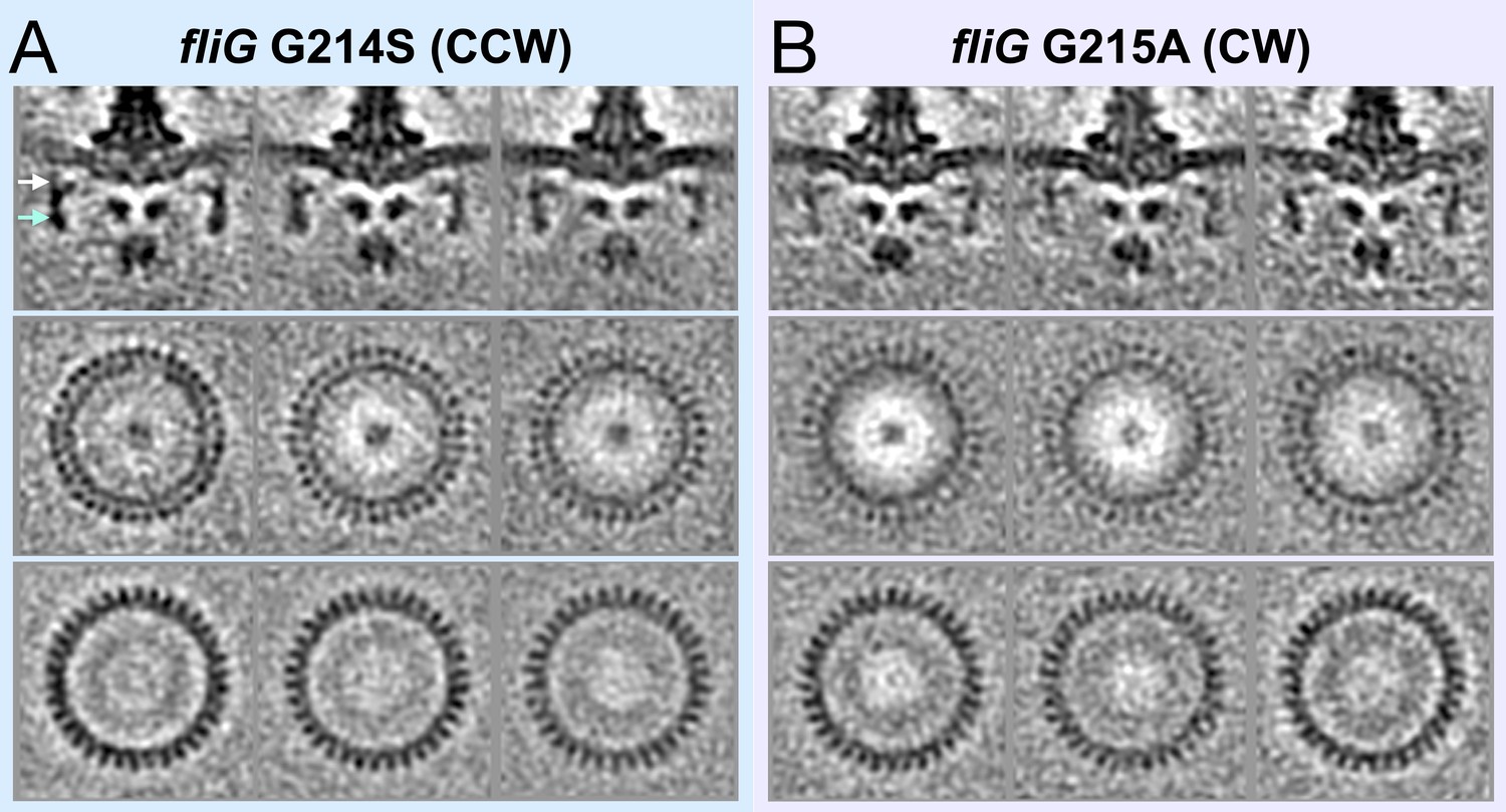
Classification of the CCW and CW flagellar motor structures reveals 34-fold symmetry of the C-ring.
(A) The top panel shows medial cross-sections of three class averages of fliG G214S (CCW). The middle panel shows perpendicular cross- sections from the top of the C-ring. The bottom panel shows perpendicular cross-sections from the bottom of the C-ring. (B). The top panel shows medial cross-sections of three class averages of fliG G215A (CW). The middle panel shows perpendicular cross-sections from the top of the C-ring. The bottom panel shows perpendicular cross-sections from the bottom of the C-ring.
Figure 2
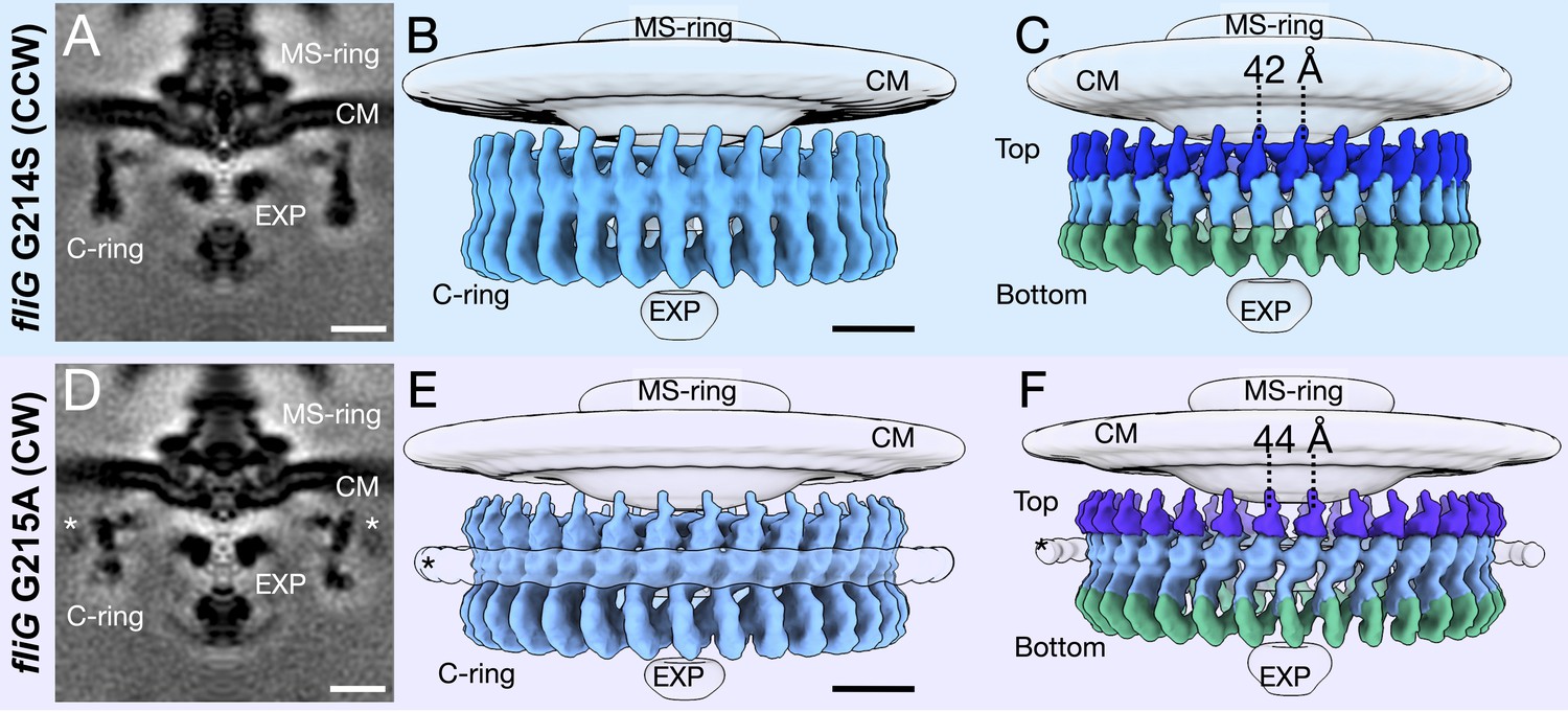
Focused refinement of the C-ring reveals differences in the CCW- and CW-motors.
(A) A medial cross-section of the focused refinement of the C-ring in V. alginolyticus fliG G214S CCW-biased variant. Scale bar 25 nm. (B) A side view of the CCW C-ring. Scale bar 10 nm. (C) A side view of the segmented map shows the top (blue), middle (light blue), and bottom (green) regions. (D) A medial cross-section of the C-ring in fliG G215A CW-locked variant. Scale bar 25 nm. (E) A side view of the focused refined CW-locked C-ring. Scale bar 10 nm. (F) A side view of the focused refined C-ring further segmented into the top (purple), middle (gray blue) and bottom (green) regions of the C-ring. The asterisk highlights the additional density (white) observed in only the CW-motor that we speculate to be CheY-P. Abbreviations: cytoplasmic membrane (CM), export apparatus and ATPase (EXP).
Figure 3 with 3 supplements
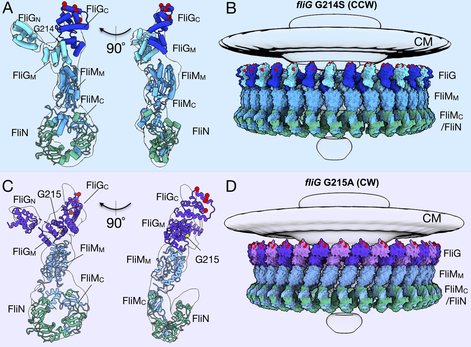
Molecular architectures of the C-ring in CCW and CW rotation.
(A) Two views varying by 90o of a single C-ring subunit model fitted in the in situ map of fliG G214S (white). (B) A side view of the CCW-motor with the model shown as surface expanded for symmetry. The density map for the MS-ring, CM, and EXP are shown in gray for reference. FliG is alternating as dark blue, and aqua, FliM is colored light blue, and FliN is shown in green. The charged residues of FliG that interact with the stator are red spheres, and glycine 214 is shown as a yellow sphere. (C) Two views varying by 90o of a single C-ring subunit model in cartoon fitted into the cryo-ET density of fliG G215A (white). (D) A side view of the CW model rendered as surfaces expanded for symmetry. FliG is alternating as purple, and mauve, FliM is gray blue, and FliN is green. The charged residues of FliG that interact with the stator are red spheres, and glycine 215 is shown as a yellow sphere. The alternating coloring of FliG reflects the different crystal structures used to build the model. To build the CCW model, we used the extended FliG, PDB-3HJL, with crystal packing. To build the CW model, we used the compact FliG, in PDB-4FHR. These models support the domain swapping hypothesis. Abbreviations: cytoplasmic membrane (CM), export apparatus and ATPase (EXP).
Figure 3—figure supplement 1
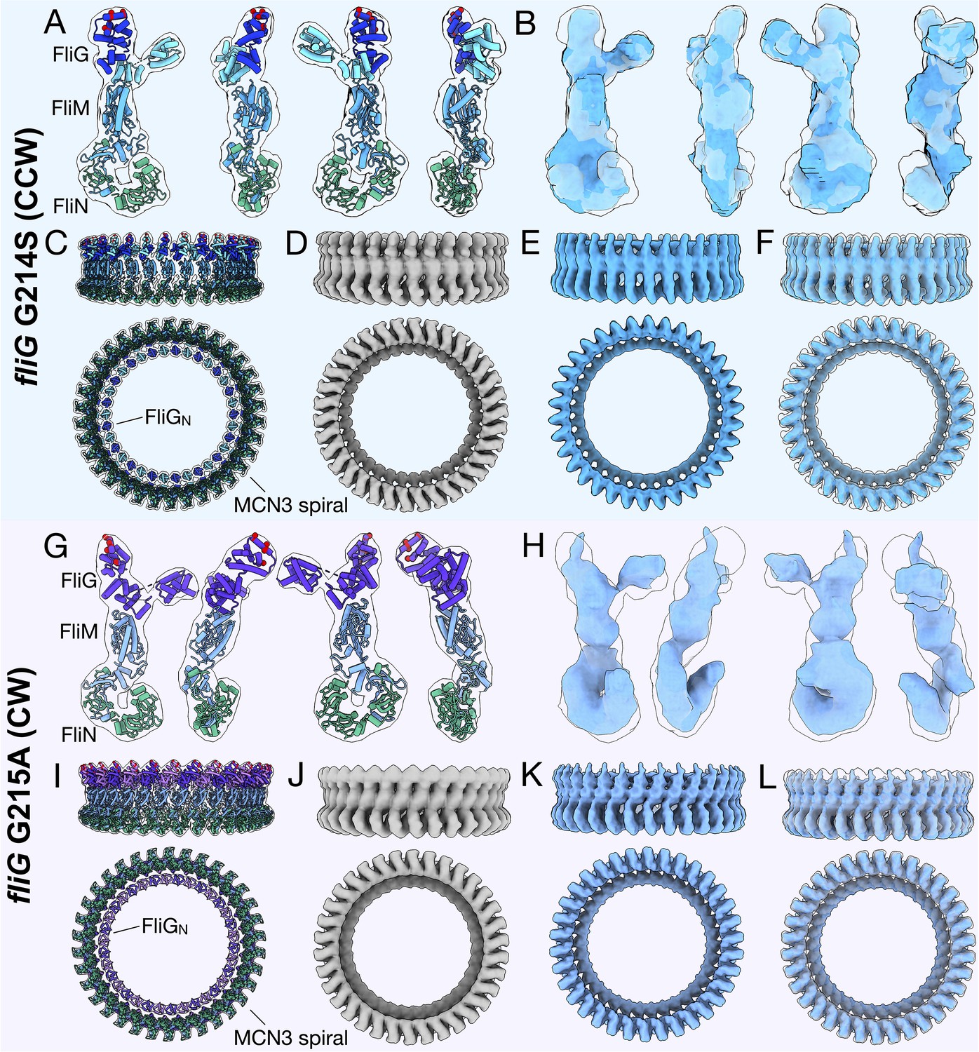
In silico maps reflect similar features as experimental data.
(A) The in silico map (gray transparent) generated at 18 Å from the CCW psuedoatomic model in fliG G214A (cartoon), views differing by 90o. FliG is alternating as dark blue, and aqua, FliM is colored light blue, and FliN is shown in green. The charged residues of FliG are red spheres. (B) The cryo-ET map (light blue) overlaid with the in silico map (gray transparent), are viewed by 90o. (C) The CCW model (cartoon) expanded for symmetry used to generate the 18 Å in silico map with the transparent map shown around as seen from the side and bottom. (D) The in silico map in gray. (E) The cryo-ET map is shown in light blue. (F) Overlay of the in silico map (gray transparent) with the cryo-ET map (light blue). (G) The in silico map (gray transparent) generated at 19 Å from the CW psuedoatomic model (cartoon) with views differing by 90o. FliG is alternating as purple, and mauve, FliM is gray blue, and FliN is green. The charged residues of FliG are red spheres. (H) The cryo-ET map (gray blue) overlaid with the in silico map (white), views differing by 90o. (I) The CW model (cartoon) expanded for symmetry used to generate the 19 Å in silico map, the model is shown as cartoon and the map as transparent gray. (J) The in silico map (gray transparent). (K) The cryo-ET map (gray blue). (H) Overlay of the in silico (gray transparent) and in situ (gray blue) map.
Figure 3—figure supplement 2
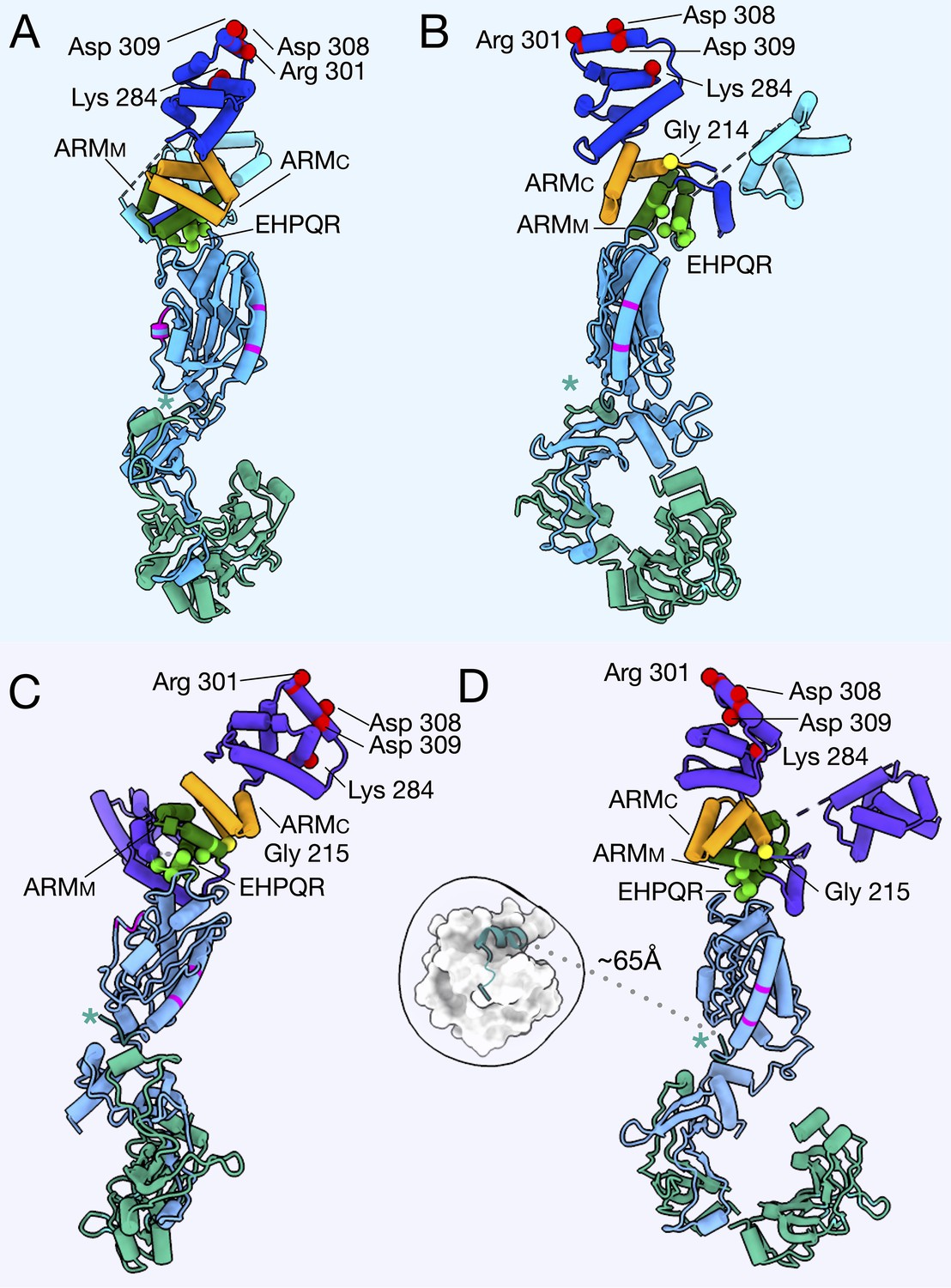
The important regions biochemically and structurally of the C-ring in the CCW and CW models.
The CCW-biased model is shown from the (A) outside, and (B) side with FliGNM in aqua, FliGc in blue, ARMM in green, ARMC in orange, FliM in light blue, and FliN in green. The FliG glycine, G214, involved in the CCW-biased model, is shown as a yellow sphere. The CW-locked model (C) from front (D) side view, FliG in purple, ARMM in green, ARMC in orange, FliM in gray blue, and FliN in green. The glycine that was mutated for the CW-locked variant, G215 is shown as a yellow sphere. In both models the charged residues, Lys 284, Arg 301, Asp 308, and Asp 309 (Nishikino et al., 2016), that interact with the stator are shown as red spheres. The EHPQR residues, EHPQ144-147, R179 (green spheres), retain the FliGMC and FliMM interface (Park et al., 2006; Sakai et al., 2019). The FliMM are residues that have been shown to interact with neighboring FliM molecules in E. coli or Salmonella, are shown in magenta. The residues in our model are located on the sides of FliM such that they would be able to interact with a neighboring C-ring subunit. FliM is orientated such that the N-terminus of FliM (teal, asterisk) would be able to extend from FliM to interact with CheY-P. (D) The CW-locked FliMM, is depicted in cartoon with CheY-P (1F4V [Lee et al., 2001a]) placed in the extra density around the C-ring (white). This shows that FliM could interact with CheY-P if the extra density is in fact CheY-P.
Figure 3—figure supplement 3
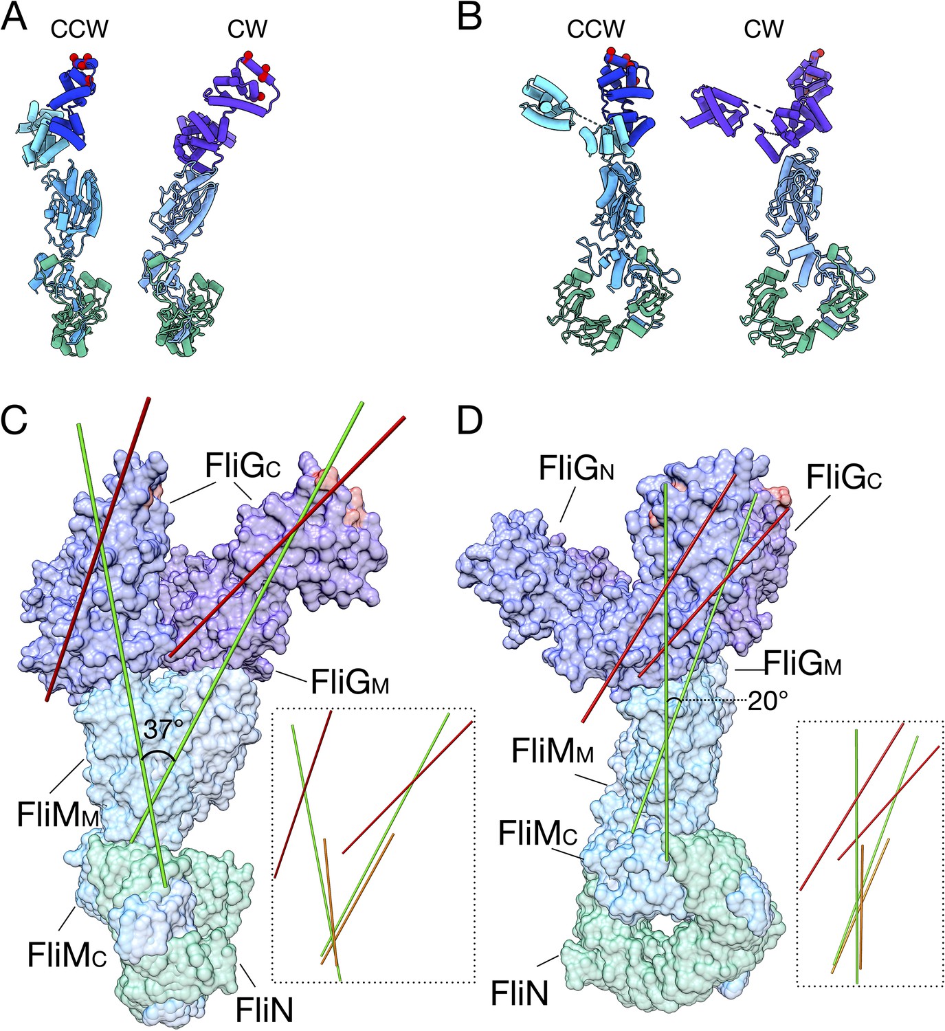
The FliG conformational change results in a tilt about FliM to change the presentation of FliGC to the stator.
(A) The CCW (left, FliG blue) and CW (right, FliG purple) models of the C-ring are shown from the front. (B) The CCW (left, FliG blue) and CW (right, FliG purple) models of the C-ring are shown from the side. (C) The CCW and CW models are overlaid with each other in the same orientation as in panel A. Using UCSF Chimera (Pettersen et al., 2004) an axes was drawn through the center of the model, FliGMC shown in red, FliGMC and FliMM in green, and FliMM alone in orange. The insets show axes drawn without the protein model for easier visualization. (D) The CCW and CW models are overlaid with each other in the same orientation as in panel B. Using UCSF Chimera (Pettersen et al., 2004) an axes was drawn through the center of the model, FliGMC shown in red, FliGMC and FliMM in green, and FliMM alone in orange. The insets show axes drawn without the protein model for easier visualization.
Figure 4
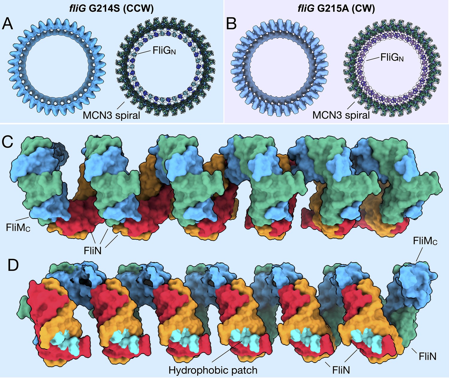
FliMC and FliN form a continuous spiral structure at the base of the C-ring.
(A) A bottom view of the fliG G214S (CCW) motor map alone (light blue), and the model (cartoon) expanded for symmetry in the in situ map (gray transparent). (B) A bottom view of the fliG G215A (CW) motor map alone (gray blue), and the model (cartoon) expanded for symmetry in the in situ map (gray transparent). (C) A view from the outside periphery, and (D) a view from the center or inside looking out, are surface representations of six subunits that form a portion of MCN3 spiral from the CCW model, with one FliMC (light blue), and three FliN molecules (green, red, and orange). The hydrophobic patch of FliN (McMurry et al., 2006), L68, A93, V111, V113, Y118, that had been shown to interact of the FliH (cyan) points toward the center of the C-ring.
Figure 5
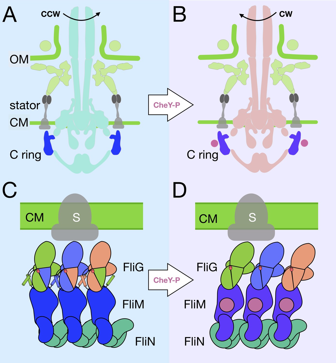
A model for the rotational switching.
(A) A cartoon of the intact CCW-motor with the C-ring highlighted in blue, and the other conserved regions that have been resolved in teal, the Vibrio-specific proteins in light green, PomAB is colored gray as it has yet to be resolved in detail in Vibrio. (B) A cartoon of the intact motor that is rotating CW, C-ring is colored purple, the other conserved structures in coral, PomAB in gray, and CheY-P in pink. (C) A cartoon representation of the C-ring rearrangement upon CheY-P binding and rotational switching to the CW sense. In CCW rotation, the intermolecular interactions of FliG ARMM and ARMC are possible because helixNM and helixMC are ordered. The Gly-Gly flexible region is depicted by red circles. The stator (gray) is shown to interact with FliGC. Upon CheY-P binding, the C-ring undergoes a conformational change that produces CW rotation. During this transition, the center of mass tilts laterally and slightly outward. In CW rotation there are intramolecular interactions of FliG ARMM and ARMC. CheY-P (dark purple) is shown bound to FliM, and the stator (gray) interacts with FliGC. We hypothesize that the conformational change in FliG is initiated in vivo by CheY-P binding, and this switches the rotational direction of the C-ring by changing how FliGC interacts with the stator. FliG undergoes a conformational change and FliM tilts about the base of the spiral. The spiral ensures that the C-ring subunits are connected while FliG and FliM undergoes large conformational changes.
Videos
Video 1
Focused refinement of the C-ring reveals conformational change during rotational switching.
The video starts with a fliG G214S motor, a mutation leads to a strong preference for CCW rotation, without symmetry applied. The C-ring is highlighted in blue. The video then zooms in to a focused refined C-ring, with much higher resolution, and turns in the CCW (looking down from the flagellum) direction. The pseudo-atomic model appears as cartoon in the map, as the map fades the model turns into surface rendering. Transparent density, that is likely CheY-P, binds and triggers the conformational change of rotor into the CW architecture. The video toggles between CCW and CW pseudo-atomic models in surface rendering to visualize the global changes of the C-ring architecture. It ends with the model spinning in the CW direction. The color scheme is the same as the paper. The video was rendered using ChimeraX.
Video 2
C-ring rearrangement leads to altered FliGC presentation to the stator.
The video starts with a side view of the CCW pseudo-atomic model in surface rendering, and the view rotates so that we are looking down on the C-ring from the flagellum. We can see the charged residues of FliGCC that interact with the stator. The video toggles between CCW and CW models, and asterisks appear to mark the charged residues of every other FliG. This highlights the large change,~40 Å, in FliG upon switching. A morphing of four adjacent subunits shows the dramatic movement of FliGC relative to the stator from the top view, and side view, the CCW model is shown as transparent. The video ends with the CW pseudo-atomic model. The video was rendered using ChimeraX.
Video 3
A model for the rotational switching.
The psudeo-atomic CCW model in surface rendering side view is rotated such we are looking up the motor toward the flagellum. The MCN3 spiral is in view, and the hydrophobic patch of FliN that interact with FliH is highlighted. The view then rotates back through the side view to top view, where the charged residues of FliGC are highlighted. The view returns to side view and zooms into a patch of four adjacent subunits. The CCW subunits morph into the CW architecture, highlight the large lateral change about FliM, and the domain swapping occurs as the FliG ARMMC interactions change from intramolecular to intermolecular. The MCN3 spiral exhibits little change. The video ends with the CW psudeo-atomic model. The video was rendered using ChimeraX.
Tables
Table 1
Cryo-ET data used in this study.
| Strain genotype | Tomograms | Motors |
|---|---|---|
| fliG-G214S | 259 | 2221 |
| fliG-G215A | 220 | 1618 |
Table 2
Strains and plasmids.
| Strains or plasmids | Genotype or description | Reference or source |
|---|---|---|
| V. alginolyticus | ||
| VIO5 | Wild-type strain of a polar flagellum (Rif+ Pof+ Laf-) | Okunishi et al., 1996 |
| KK148 | VIO5 flhG (Multi-Pof+) | Kusumoto et al., 2008 |
| NMB328 | KK148 ΔfliG (Pof-) | This study |
| E. coli | ||
| DH5α | Host for cloning experiments | Grant et al., 1990 |
| S17-1 | recA hsdR thi pro ara RP-4 2-tc::Mu-Km::Tn7 (Tpr Smr) | Simon et al., 1983 |
| β3914 | β2163 gyrA462 zei-298::Tn10 (Kmr Emr Tcr) | Le Roux et al., 2007 |
| Plasmids | ||
| pMMB206 | Cmr, PtacPlacUV5 | Morales et al., 1991 |
| pNT1 | fliG in pMMB206 | Takekawa et al., 2014 |
| pSW7848 | Suicide plasmid for allele exchange | Val et al., 2012 |
| pHIDA3 | SacI fragment of fliF-fliG (55–175 internal deletion of FliG) in pSW7848 | Mino et al., 2019 |
Additional files
Download links
A two-part list of links to download the article, or parts of the article, in various formats.
Downloads (link to download the article as PDF)
Open citations (links to open the citations from this article in various online reference manager services)
Cite this article (links to download the citations from this article in formats compatible with various reference manager tools)
The flagellar motor of Vibrio alginolyticus undergoes major structural remodeling during rotational switching
eLife 9:e61446.
https://doi.org/10.7554/eLife.61446


