Three-dimensional reconstruction of a whole insect reveals its phloem sap-sucking mechanism at nano-resolution
- Institute of Insect Science, Zhejiang University, China
- Department of Pathology of Sir Run Run Shaw Hospital, and Center of Cryo-Electron Microscopy, School of Medicine, Zhejiang University, China
- State Key Laboratory for Managing Biotic and Chemical Threats to the Quality and Safety of Agro-Products, Key Laboratory of Biotechnology in Plant Protection of Ministry of Agriculture and Zhejiang Province, Institute of Plant Virology, Ningbo University, China
- Carl Zeiss (Shanghai) Co., Ltd.60 Meiyue Road, China (Shanghai) Pilot Free Trade Zone, China
- Department of Medical Biology, Amsterdam University Medical Centers, University of Amsterdam, Netherlands
- Université Côte d’Azur, CNRS, Université Côte d’Azur, Institute of Biology Valrose, Parc Valrose, France
Figures
Figure 1 with 4 supplements
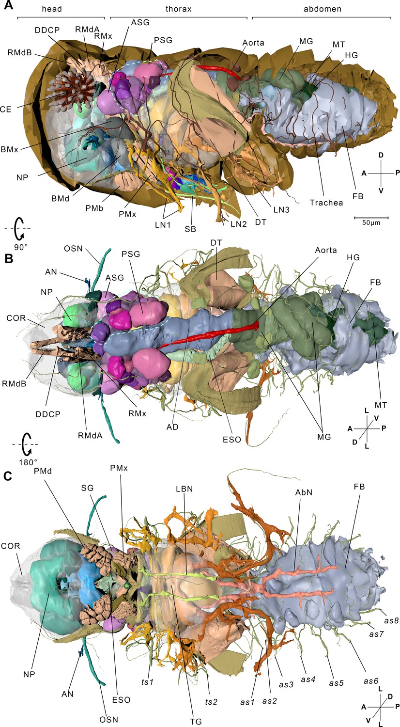
Reconstructed internal structures of a first instar nymph.
(A) Left-lateral view. Half of the exoskeleton is shown. The body can be grouped into three parts, the head, thorax, and abdomen. The green dotted line indicates principle salivary gland (PSG). (B) Dorsal view. All exoskeleton is removed. (C) Ventral view. AbN, abdominal nerve; AD, anterior duct; AN, antennal nerve; as1–as8, spiracles on the first to eighth abdominal segments; ASG, accessory salivary gland; BMd, base of the mandibular stylet; BMx, base of the maxillary stylet; CE, compound eye; COR, cortex; DDCP, dorsal dilator of the cibarial pump; DT, depressor of the trochanter; ESO, esophagus; FB, fat body; HG, hindgut; LBN, labial nerve; LN1, proleg nerve; LN2, mesoleg nerve; LN3, metaleg nerve; MG, midgut; MT, Malpighian tubule; NP, neuropil; OSN, olfactory sensory nerve; PMd, protractor of the mandibular stylet; PMx, protractor of the maxillary stylet; RMdA and RMdB, retractor of the mandibular stylet A and B; RMx, retractor of the maxillary stylet; SB, stylet bundle; TG, thoracic ganglion; ts1, spiracle on the mesothoracic segment; ts2, spiracle on the metathoracic segment. See reconstructed central nervous system in Figure 1—figure supplement 1, serial block-face scanning electron microscopy (SBF-SEM) data of the whole insect in Figure 1—video 1, SBF-SEM data of the nervous system in Figure 1—video 2 and reconstructed systems in Figure 1—video 3. Axis: D, dorsal; V, ventral; A, anterior; P, posterior; M, medial; L, lateral.
Figure 1—figure supplement 1
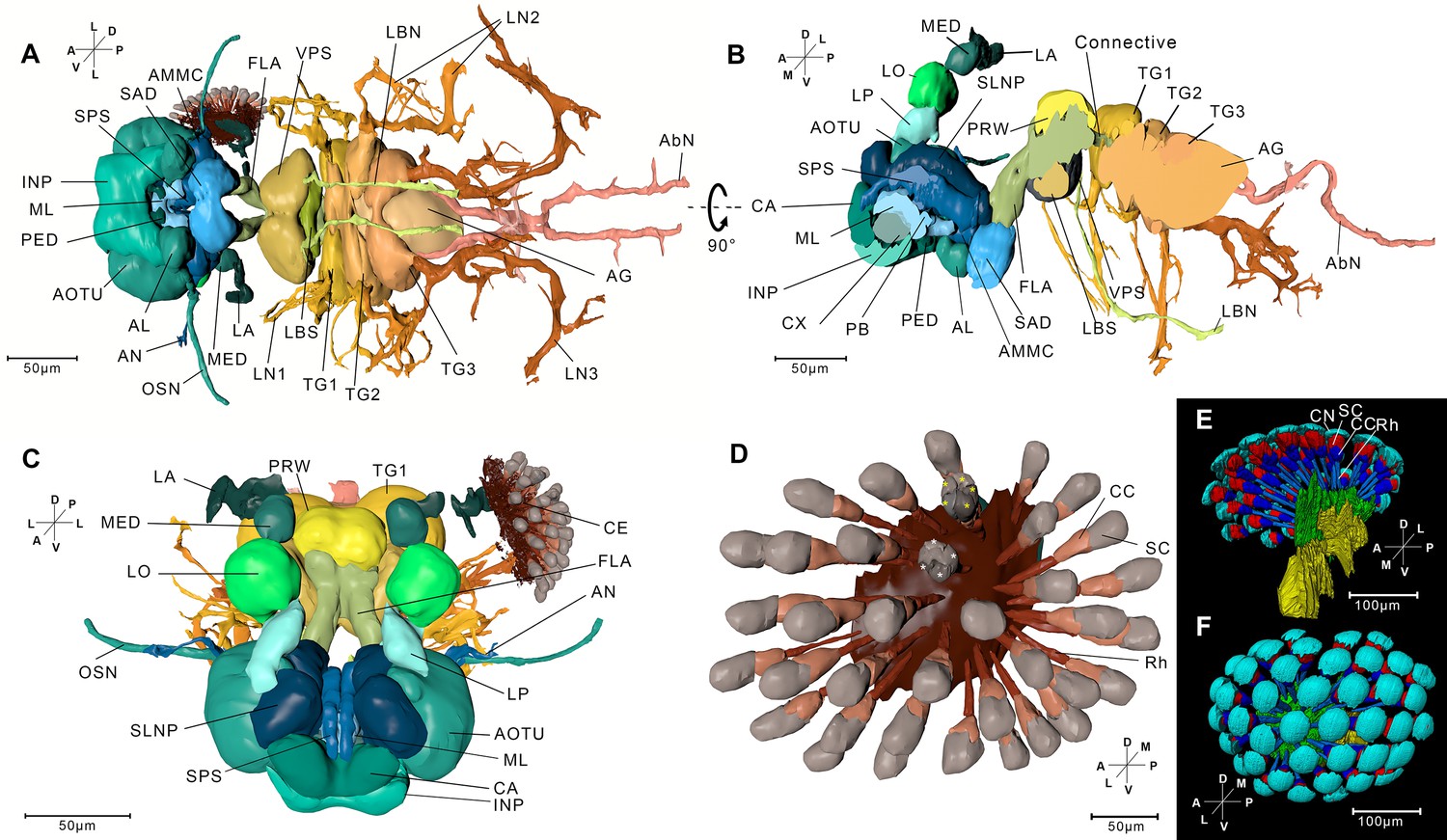
Reconstructed central nervous system and the compound eye.
To clearly show the position of different neuropils, the cortex is removed. (A) Ventral view. A total of 24 neuropils in the central nervous system were reconstructed, including 19 in the brain, a connective between the labial sensory center and the prothoracic ganglion, three thoracic neuropils, and a merged abdomen neuropil. The protocerebrum, deutocerebrum, and tritocerebrum are fused and form an esophageal foramen through which the alimentary canal passes. Readers are encouraged to see the 3D PDF to learn spatial relationships of the neuropils. (B) Left-lateral view. Left half of the neuropils are removed. (C) Front view. AbN, abdominal nerve; AG, abdominal ganglion; AL, antennal lobe; AMMC, antennal mechanical and motor center; AN, antennal lobe; AOTU, anterior optic tubercle; CA, calyx; CE, 601 compound eye; CX, central complex; FLA, flange; INP, inferior neuropil; LBN, labial nerve; LA, lamina; LBS, labial sensory center; LN1, proleg nerve; LN2, mesoleg nerve; LN3, metaleg nerve; LO, lobula; LP, lobula plate; MED, medulla; ML, medial 603 lobe; OSN, olfactory sensory nerve; PB, protocerebral bridge; PED, pedunculus; PRW, prow; SAD, saddle; SPS, superior posterior slope; SLNP, superior lateral neuropil; TG1, prothoracic ganglion; TG2, mesothoracic ganglion; TG3, metathoracic ganglion; VPS, ventral pharyngeal sensory center. (D) A compound eye of Sample 1. The compound eyes of the first instar nymph comprise less ommatidia than the adult. Most crystalline cones of the ommatidia have four compartments, and a small number of the ommatidia have five compartments. The yellow asterisks indicate the crystalline cones (CCs) in an ommatidium with five Samper cells (SCs). The white asterisks indicate CCs in an ommatidium with four SCs. Rh, rhabdom. (E) The compound eye of Sample 2 containing 42 ommatidia. CN, cornea. (F) Top view of the compound eye of Sample 2. All 42 ommatidia are shown. Axis labels are the same as those used in Figure 1.
Figure 1—video 1
The volume data of sample 1.
The images of x–y, x–z, and z–y planes are presented.
Figure 1—video 2
The volume data of sample 2.
The images of x–y, x–z, and z–y planes and the reconstructed cortex are presented.
Figure 1—video 3
The three-dimensional presentation of different systems and musculature based on the reconstructed model of sample 1.
Figure 2 with 6 supplements
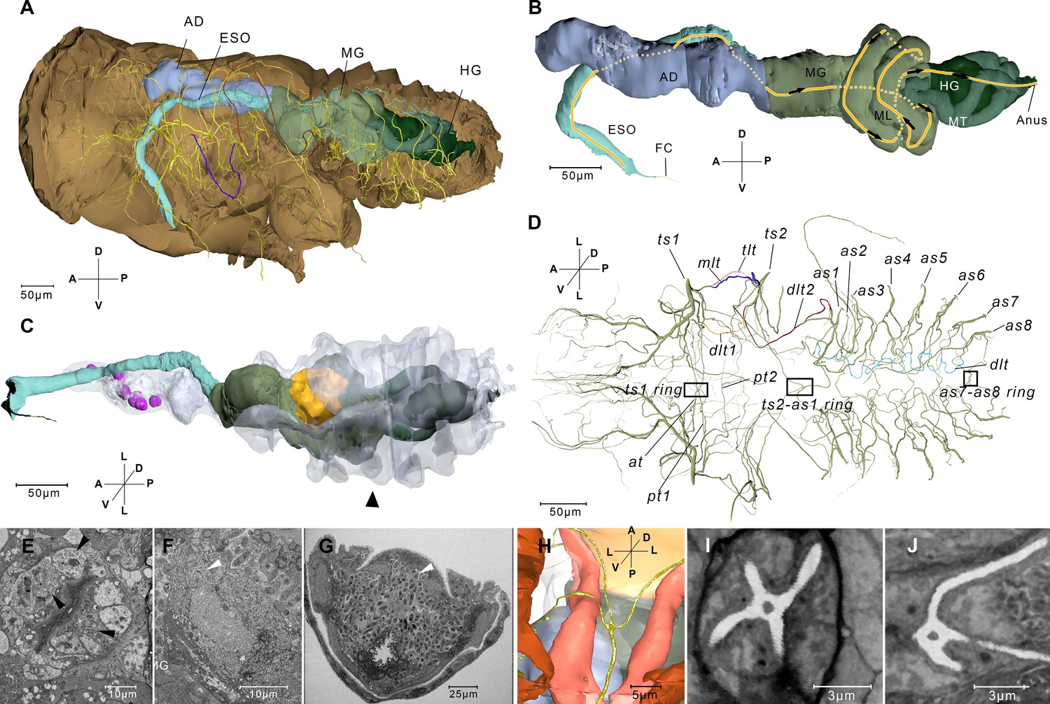
Reconstructed alimentary canal and tracheal system and endosymbionts.
(A) The relationship of the tracheal system and the alimentary canal in the body. (B) Right-lateral view of the alimentary canal. The yellow line and the arrows indicate the direction in which the food can move in the midgut loop (ML). Details of the alimentary system are given in Figure 2—figure supplement 2. (C) The reconstructed alimentary canal and symbionts. Cells that accommodate symbionts in the anterior diverticulum (magenta), cells that accommodate thread-like symbionts (yellow), and the large mycetocyte that accommodate yeas-like symbionts (arrowhead) are shown. The anterior diverticulum and the large mycetocyte are rendered transparent. (D) Ventral view of the tracheal system. The rectangles indicate three four-way tracheal rings. (E) Anterior diverticulum symbionts are in different cells on the wall. The arrow heads indicate symbionts in three cells. Another image of this kind of symbiont is given in Figure 2—figure supplement 2A. (F) The thread-like symbionts are in a cell near the midgut (MG). The arrow head indicates the thread-like symbionts. The image of the thread-like symbionts in the midgut from another sample is given in Figure 2—figure supplement 2C. (G) A cross section of the abdomen and the yeast-like symbionts (arrowhead). A higher magnification image is given in Figure 2—figure supplement 2D. See serial block-face scanning electron microscopy (SBF-SEM) data of G in Figure 2—video 1. (H) Reconstructed ts2-as1 four-way tracheal ring (green). The detailed features of the spiracle are given in Figure 2—figure supplement 3. (I and J) Two slices reconstructed from the serial block-face scanning electron microscopy (SBF-SEM) data set showing the ts1–ts2 and the ts2–as1 four-way tracheal ring respectively. AD, anterior diverticulum; as1–as8, spiracles on the first to eighth abdominal segments; at, the trachea extending anteriorly from the tracheal vestibule of ts1; dlt, dorsal longitudinal trunk; dlt1, dorsal longitudinal trunk from ts1; dlt2, dorsal longitudinal trunk from ts2; ESO, esophagus; FC, food canal; HG, hindgut; MG, midgut; pt1, the trachea extending posteriorly from ts1; mlt, mesoleg trunk; pt2, the second trachea extending posteriorly from ts1; tlt, thorax lateral trunk; ts1, the spiracle on the mesothoracic segment; ts2, the spiracle on the metathoracic segment. Axis labels are the same as those used in Figure 1.
Figure 2—figure supplement 1
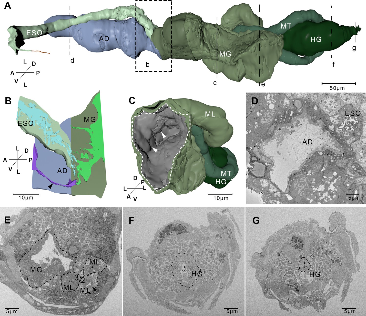
Reconstructed alimentary canal and serial block-face scanning electron microscopy (SBF-SEM) images.
(A) Ventral view of the alimentary canal. The images in (D–G) show cross sections at the positions d–g, respectively. AD, anterior diverticulum; ESO, esophagus; HG, hind gut; MT, Malpighian tubule. The midgut can be divided into an anterior sac and a midgut loop. Two MTs arise from the junction between the midgut and the hindgut. (B) The connection site of the esophagus (ESO), the anterior diverticulum (AD), and the midgut (MG). This region is indicated by the box b in panel (A). Left half of the wall has been removed to show the lumen (light blue in the ESO, purple in the AD, and light green in the MG). The arrowhead indicates a narrow lumen region (purple) between AD and MG. (C) 3D image of the posterior region of the midgut. The virtual cutting site is labeled c in panel (A). The dotted line indicates the outline of the lumen. The arrowheads indicate the protuberance of the inner surface. These protuberances enable the midgut to expand when it is full of food. (D) Cross section of the anterior diverticulum (AD) and the esophagus (ESO). This image corresponds to site d in panel (A). (E) Midgut (MG) and midgut loop (ML) indicated by dotted lines. The arrowhead indicates the narrow lumen in ML. The asterisks indicate the lumen that is squeezed by the wall of ML. The inner surface of the whole midgut is covered by a dense layer of microvilli. The numbers indicate that the food moves backward through position one first, then it moves forward through position 2, and at last it moves backward through position three to the hindgut. This image corresponds to site e in panel (A). (F) Posterior region of HG. HG is indicated by the dotted line. The asterisk indicates the lumen of HG. Longitudinal ridges on the inner wall make the lumen narrow. This image corresponds to site f in panel (A). (G) The anus is indicated by the dotted line. The opening of the anus is closed by four ridges on the wall. This image corresponds to site g in panel (A). Axis labels are the same as those used in Figure 1.
Figure 2—figure supplement 2
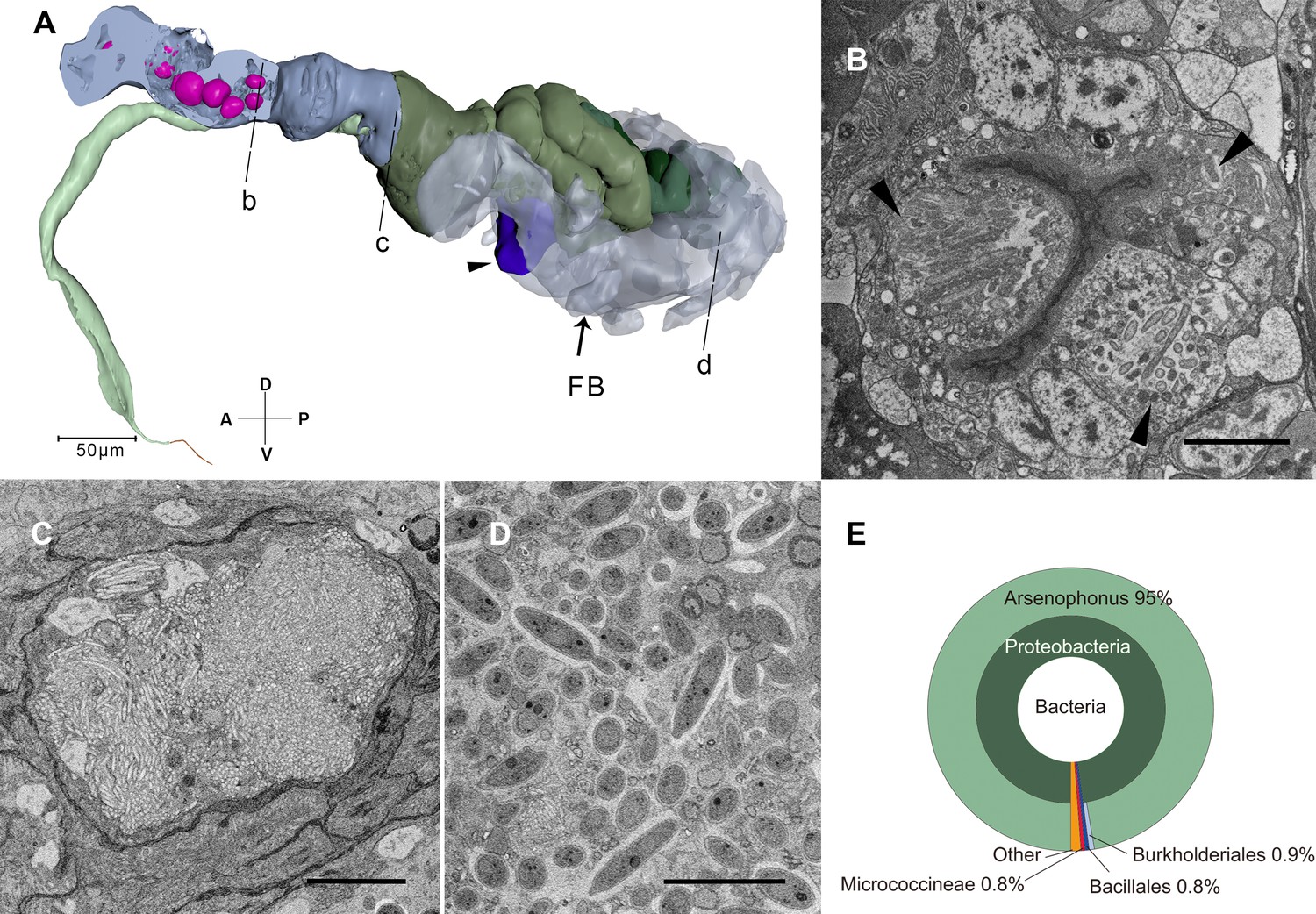
Serial block-face scanning electron microscopy (SBF-SEM) sections of symbionts and their positions in the nymph.
(A) The reconstructed alimentary canal and symbionts. Right half of the anterior diverticulum has been removed to show the cavities in cells where the symbionts reside (magenta). The fat body (FB) that most of the YLS reside in is rendered translucent. A few YLSs are dispersed in the body cavity including the head and legs. The thread-like symbionts are in the cell indicated by the arrow head. b–d represent the positions of the sections in panels (B–D). (B) Anterior diverticulum symbionts are in different cells in the anterior diverticulum wall. The arrowheads indicate symbionts in three cells. Scale bar = 5 μm. (C) Thread-like symbionts occupy the gut lumen. These symbionts were observed where the midgut, esophagus, and anterior duct merge only in Sample 3. Scale bar = 5 μm. (D) Yeast-like symbionts in the FB. Scale bar = 10 μm. (E) Taxonomic composition of the bacterial microbiome from anterior diverticulum using 16S rDNA sequencing. The size of the fan represents the relative proportion of the bacteria. Axis labels are the same as those used in Figure 1.
Figure 2—figure supplement 3
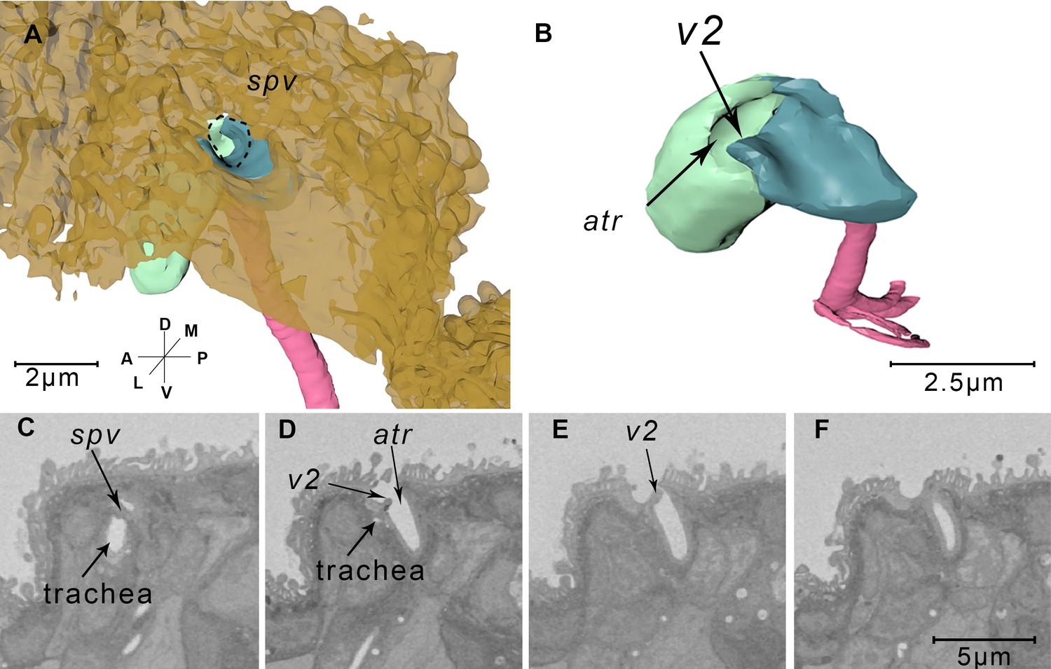
Reconstructed spiracles and corresponding serial block-face scanning electron microscopy (SBF-SEM) images.
(A) The reconstructed spiracle. The cuticle is rendered transparent brown. The pit on the body surface leads into a cuticle lining cavity, the atrium (atr). The trachea (pink) is separated from the external environment by a spiraclular valve (spv) indicated by the dotted line. (B) The close up view of reconstructed abdominal spiracle. The spiracle atria (atr) are separated into two parts (green and blue) by a second valve (v2). (C–F) Serial sections from the SBF-SEM data through an abdominal spiracle. The two valves are shown respectively in panel (C) and panel (E). Axis labels are the same as those used in Figure 1.
Figure 2—figure supplement 4
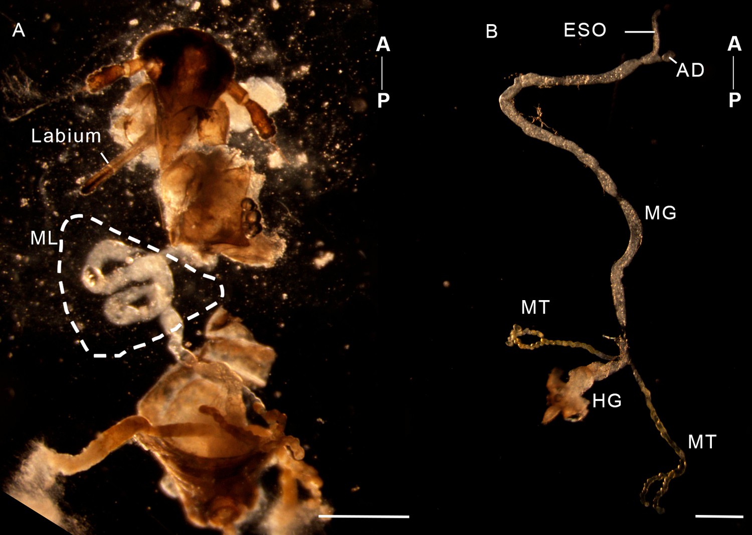
The dissected alimentary canals of a female adult N. lugens.
(A) The abdomen was partly removed and the midgut loop (ML) was exposed. (B) The midgut loop could be easily straightened once removed into a drop of PBS. AD, anterior diverticulum; ESO, esophagus; HG, hindgut; MT, Malpighian tube. Scale bar = 500 µm. Axis labels are the same as those used in Figure 1.
Figure 2—figure supplement 5
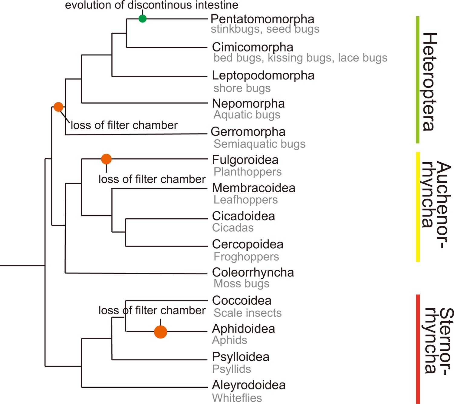
Phylogeny of higher taxa in the Hemiptera (Johnson et al., 2018).
Common insect names are shown and filter chamber loss events are indicated. Not all members in Aphidoidea lost the filter chamber.
Figure 2—video 1
The volume data of sample 5.
The images of x–y, x–z, and z–y planes and the reconstructed body are presented.
Figure 3 with 3 supplements
Reconstructed cephalic endoskeleton and mouthpart.
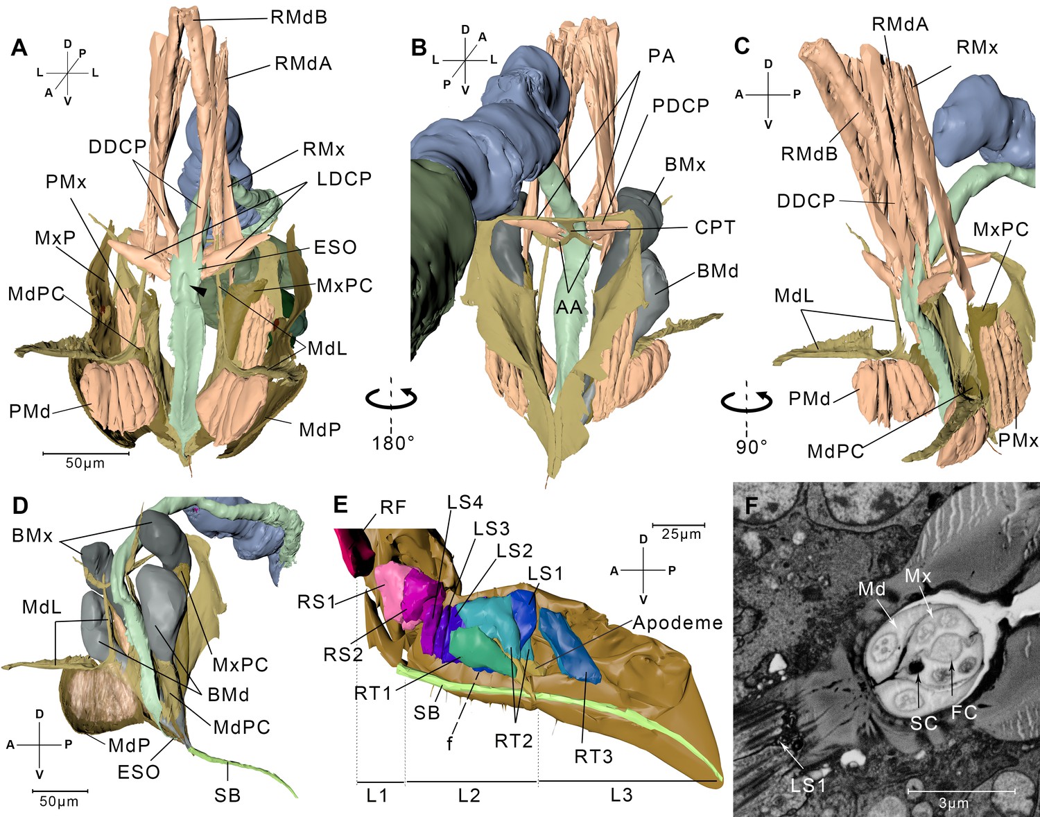
(A) Front view of the cephalic endoskeleton and musculature. The arrowhead indicates the invagination on the anterior wall of the cibarial pump. The cephalic structures without the alimentary canal are in Figure 3—figure supplement 1A,B. (B) Back view of the cephalic endoskeleton and musculature. (C) Left-lateral view of the cephalic endoskeleton and musculature. (D) Left-lateral view of the junction between the base of the stylets and the stylet bundle. The muscles are rendered translucent, and the left mandibular lever with muscles is removed for a better view of the mandibular pouch (MdPC). (E) Left-lateral view of the mouthpart. Left half of the exoskeleton is removed. The overall view of the head and the mouthpart is in Figure 3—figure supplement 1C. (F) A slice from the serial block-face scanning electron microscopy (SBF-SEM) data set at the f position in E. AA, anterior arm; BMd, base of the mandibular stylet; BMx, base of the maxillary stylet; CPT, corpotentorium; DDCP, dorsal dilator of the cibarial pump; ESO, esophagus; FC, food canal; L1, L2, L3, The first, second, and third segments of the labium; LDCP, lateral dilator of the cibarial pump; LS1–4, lockers of the stylets 1–4; Md, mandibular stylet; MdL, mandibular lever; MdP, mandibular plate; MdPC, mandibular pouch; Mx, maxillary stylet; MxP, maxillary plate; MxPC, maxillary pouch; PA, posterior arm; PDCP, posterior dilator of the cibarial pump; PMd, protractor of the mandibular stylet; PMx, protractor of the maxillary stylet; RF, rotator of the first labial segment; RMdA, retractor of the mandibular stylet A; RMdB, retractor of the mandibular stylet B; RMx, retractor of the maxillary stylet; RS1–2, rotators of the second labial segment; RT1–3, retractors of the third labial segment 1–3; SB, stylet bundle; SC, saliva canal. See SBF-SEM data of the labium in Figure 3—video 1. Axis labels are the same as those used in Figure 1.
Figure 3—figure supplement 1
Cephalic endoskeleton and muscles and structures that are involved in the feeding process.
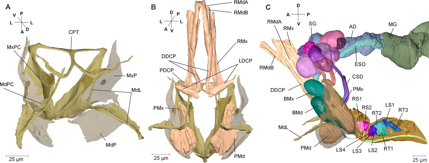
(A) Cephalic endoskeleton. The mandibular plate (MdP) and maxillary plate (MxP) are rendered transparent. (B) Dorsal view of cephalic endoskeleton and muscles. CPT, corpotentorium; DDCP, dorsal dilator of the cibarial pump; LDCP, lateral dilator of the cibarial pump; MdPC, mandibular pouch; MxPC, maxillary plate; PDCP, posterior dilators of the cibarial pump; PMd, protractor of the mandibular stylet; PMx, protractor of the maxillary stylet; RMdA and RMdB, retractor of the mandibular stylet A and B; RMx, retractor of the maxillary stylet. (C) Left-lateral view of the structures that are involved in the feeding process. The left side of the labium is removed to show inner structures. AD, anterior diverticulum; BMd, base of the mandibular stylet; BMx, base of the maxillary stylet; CSD, common salivary duct; DDCP, dorsal dilator of the cibarial pump; ESO, esophagus; LS1–4, lockers of the stylets 1–4; MdL, mandibular lever; MG, midgut; PMd, protractor of the mandibular stylet; PMx, protractor of the maxillary stylet; RMdA and RMdB, retractors of the mandibular stylet A and B; RMx, retractor of the maxillary stylet; RS1 and RS2, rotators of the second labial segment 1 and 2; RT1–3, retractors of the third labial segment 1–3; SG, salivary gland. Axis labels are the same as those used in Figure 1.
Figure 3—figure supplement 2

Microscopic images of the mouthpart.
(A and B) The first instar nymph was frozen when it was sucking the rice sap and the SEM images were taken immediately without returning to room temperature. (A) Front view. The stylets were still in the rice plant. (B) Ventral view. The nymph removed from the plant; the protruding stylets are visible. (C) The first instar nymph was frozen when it was sucking the rice sap and the SEM images were taken after returning to room temperature. The tip of the mouthpart is shown. The maxillary stylets (blue and purple) are longer than the mandibular stylets during feeding (red and green). (D) The TEM cross section of the stylet bundle. This is the same image as in Figure 3F and the color code is the same as in (C). Axis labels are the same as those used in Figure 1.
Figure 3—video 1
The volume data of sample 3.
The images of x–y, x–z, and z-y planes, the reconstructed labrum (yellow), labium (brilliant blue), and forelegs (blue) are presented.
Figure 4 with 2 supplements
Measurement of the labium, stylet, and muscles.
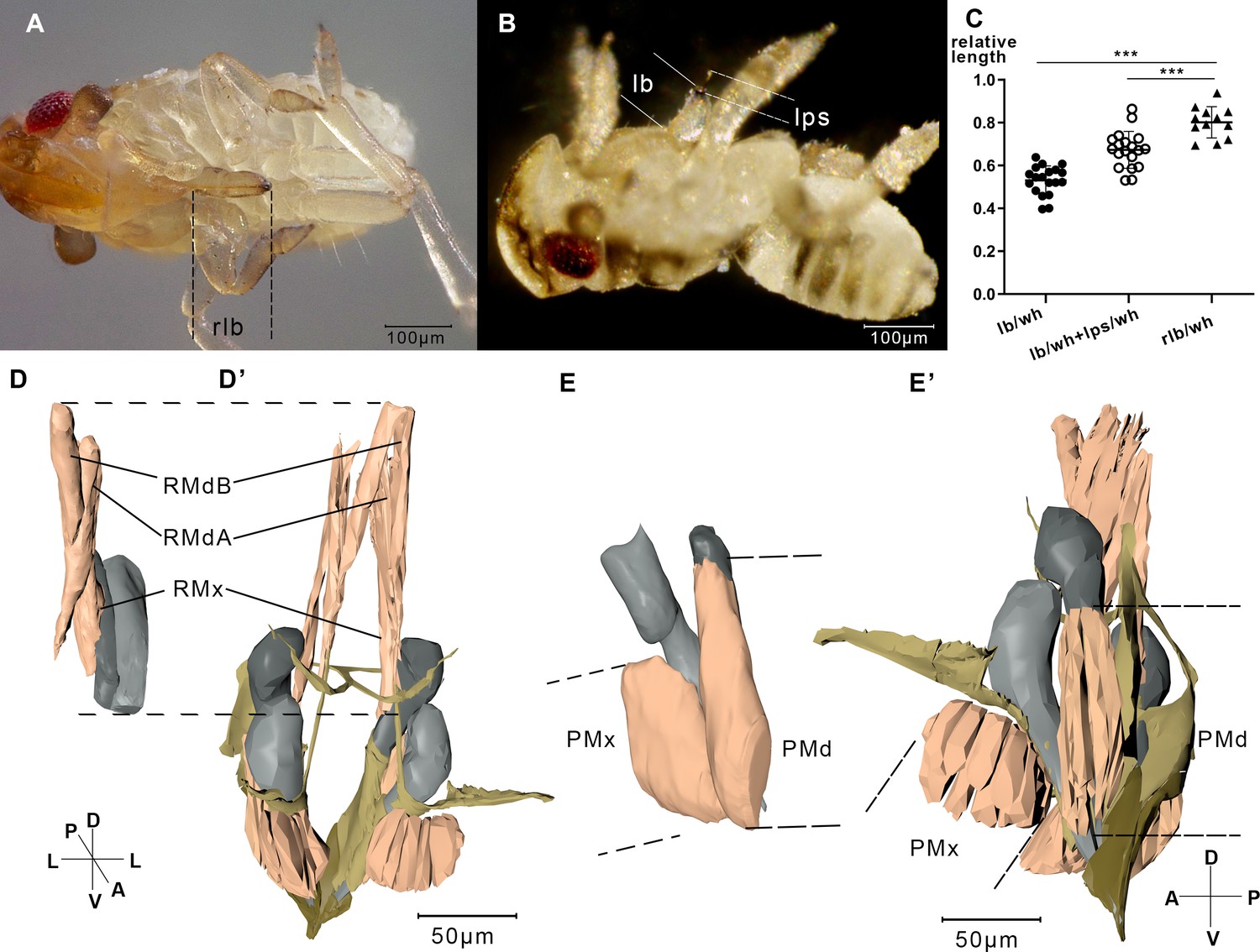
(A) A relaxing nymph. Length of the beak (lb) refers to the distance between the tip of the labium and the tip of the labrum. (B) A feeding nymph. Length of the protruding stylet (lps) in feeding nymphs refers to the distance between the tip of the labrum and the tip of the stylet bundle. (C) Relative length of the labium and the stylets in feeding nymphs and relaxing nymphs. lb, lps, and rlb were divided by the width of the head (wh) to eliminate the influence of different body size. rlb, length of the beak in relaxing nymphs. 12 of the relaxing nymphs and 19 of the feeding nymphs were measured. ***, two-tailed t-test, p<0.001. (D) Reconstructed musculature of a feeding nymph (Sample 7). RMdA = 69,720 nm, RMdB = 74,170 nm, RMx = 122,390 nm. See measured lengths and statistic tests in Figure 4—source data 1. (D’) Reconstructed musculature of a relaxing nymph (sp1). RMdA = 97,550 nm, RMdB = 111,410 nm, RMx = 161,090 nm. (E) Reconstructed musculature of a feeding nymph (sp8). PMd = 65,020 nm, PMx = 85,860 nm. (E’) Reconstructed musculature of a relaxing nymph (sp1). PMd = 39,200 nm, PMx = 82,700 nm. All length data of the muscles were obtained using the measurement module in Amira. RMdA and RMdB, retractor of the mandibular stylet A and B; RMx, retractor of the maxillary stylet; PMd, protractor of the mandibular stylet; PMx, protractor of the maxillary stylet. See musculature of feeding nymphs in Figure 4—videos 1 and 2. Axis labels are the same as those used in Figure 1.
-
Figure 4—source data 1
Measured lengths of the beaks and stylets.
Related to Figure 4C.
- https://cdn.elifesciences.org/articles/62875/elife-62875-fig4-data1-v3.xlsx
Figure 4—video 1
The volume data of sample 6.
The images of x–y, x–z, and z–y planes, the reconstructed mandibular plate (green), base of the mandibular stylet (yellow), base of the maxillary stylet (red), protractor of the mandibular stylet (blue), and protractor of the maxillary stylet (brilliant blue) are presented.
Figure 4—video 2
The volume data of the mouthpart from sample 7.
The images of x–y, x–z, and z–y planes, retractor of L3 1 (red), retractor of L3 2 (green), retractor of L3 3 (orange and light blue), locker of the stylets (yellow and magenta), and the apodeme on L3 (brilliant blue) are presented.
Figure 5 with 1 supplement

Reconstructed salivary gland and the saliva injection process.
(A) Left-lateral view. A–I, Follicles A–I; ADC, accessary duct; AG, accessory gland; ASD, anterior salivary duct; CSD, common salivary duct; DSS, dilator of the salivary syringe; ESD, efferent salivary syringe; RS, reservoir; S, stroma; SV, salivarium. The serial block-face scanning electron microscopy (SBF-SEM) slices of every follicle are given in Figure 5—figure supplement 1. (B) Ductules in the left salivary gland. Cells in the principle gland are removed. The two nuclei from each cell in Follicle A are shown in yellow and orange respectively. (C) Back view of the salivary gland. (D–I) Simulated presentation of the saliva injection process. (D) Front view of the salivary syringe. (E) A pair of DSS contracts, pulling the wall of the reservoir to the arrowed direction. Consequently, the reservoir expands. (F) Dilators of the salivary syringe relax and consequently the reservoir shrinks. (G) Lateral view of the salivary syringe. The wall cells of CSD are removed and the lumen is presented. The pair of DSS is rendered transparent. It is in the same state as the specimen of panel (D). (H) The pair of DSS contract and the reservoir expands. Saliva is pumped into the reservoir. The dotted line indicates the route of the saliva and the arrow indicates the direction of the saliva flux. (I) DSS relaxes and the reservoir shrinks, consequently saliva in the reservoir is pumped out. Axis labels are the same as those used in Figure 1.
Figure 5—figure supplement 1

Serial block-face scanning electron microscopy (SBF-SEM) sections showing cells from different follicles in the salivary gland.
(A–I) Cells from follicle A – follicle I. Dotted lines in each panel indicate the follicle cell. Follicles A, C, D, and G contain transparent vesicles (A, C, D, G). Follicle C is small and the vesicles are crowded. Follicle D contains some electron-dense materials between the vesicles. Follicle G contains the biggest vesicles. Follicle B contains semitransparent vesicles. Follicle E contains some electron-dense materials with very few vesicles (E). Follicles F and H contain opaque vesicles (F and H). Follicle I contains electron-dense vesicles (I). (J) Cells from accessory glands. (K) Efferent salivary duct. The arrow indicates the lumen of the efferent salivary duct. (L) Schematic distribution of the follicles connected by ductules. Follicle H is separated from the others. AG, accessory gland; A–I, follicle A – follicle I; ESD, efferent salivary duct. Scale bar = 5 μm.
Figure 6 with 2 supplements
Illustrated presentation of a feeding process model.
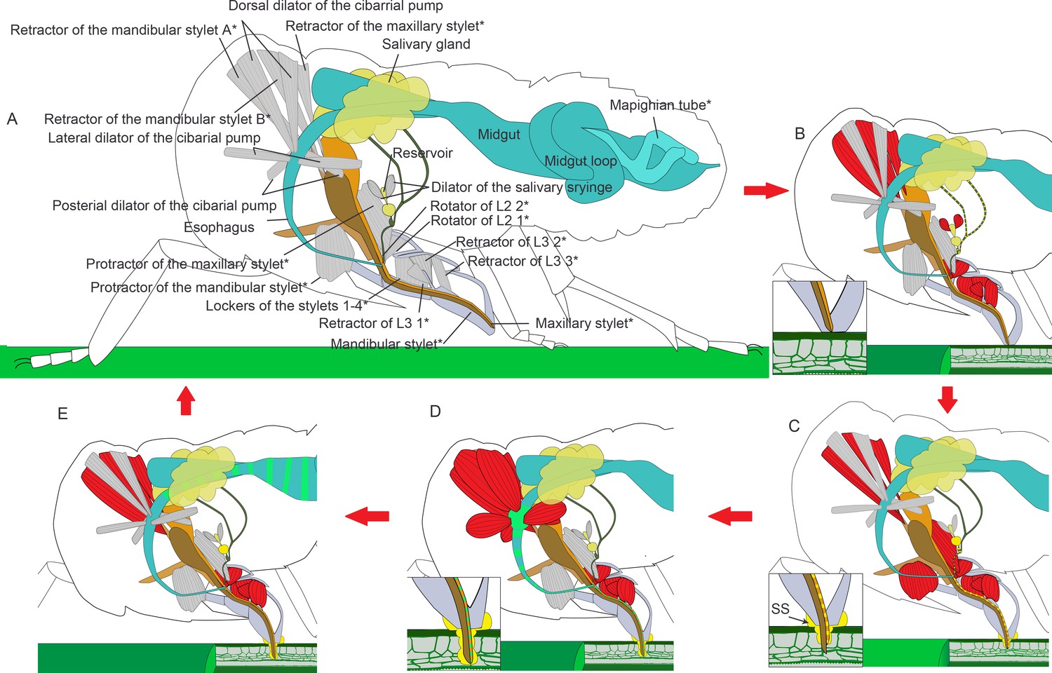
The inserts in panel (B–D) show a close view of the stylets tip. Relaxed muscles are in gray and contracting muscles are in red. (A) A relaxing insect. The stylet bundle is in the labium. *The structures are paired in the insect, but only one side of the body is shown. (B) Rotators of the L2 and retractors of L3 contract, and the labium is bent to the plant. Retractors of the mandibular and maxillary stylet contract, and the stylets are retracted to stay inside of the labium. Dilators of the salivary syringe contract to pump saliva into the reservoir and salivarium. (C) Protractor of the mandibular stylet on one side of the body contracts and the corresponding mandibular stylet stick out to dig in the plant. Protractors of the maxillary stylets contract to pull maxillary stylets out. The head lowers down to compress the labium, so the stylets can dig deeper into the plant tissue. Retractors of both the mandibular and the maxillary stylets keep contracting to pull up the mandibular and the maxillary pouch, so that the first segment of the labial can be packed into the head capsule as the head lowers down. Dilators of the salivary syringe relaxes to pump out saliva. Salivary sheath (SS) is formed at the contacting surface of the mouthpart and the plant tissue. (D) As the two mandibular stylets penetrate into the plant tissue alternately with the maxillary stylets following, all the four stylets reach the phloem tissue. Dilators of the cibarial pump contract to pump the plant sap into the cibarial pump. (E) Dilators of the cibarial pump relax to squeeze the plant sap into the midgut. See feeding process of an adult in Figure 6—video 1 and an animated feeding process in Figure 6—video 2.
Figure 6—video 1
The feeding process of an adult N. lugens.
Bending of the labium and lowering of the head can be observed.
Figure 6—video 2
The illustrated animation of the feeding process.
The illustration is based on the reconstructed model of sample 1.
Tables
Key resources table
| Reagent type (species) or resource | Designation | Source or reference | Identifiers | Additional information |
|---|---|---|---|---|
| Software, algorithm | GraphPad Prism 8 | GraphPad Prism | RRID:SCR_002798 | |
| Software, algorithm | Adobe Illustrator | Adobe Inc | RRID:SCR_014198 | |
| Software, algorithm | Amira 6.8 | Thermo Fisher Scientific | RRID:SCR_007353 |
Table 1
Samples used for reconstruction.
| Sample | Body part | Slices | Pixel size (nm) | z-resolution (nm) |
|---|---|---|---|---|
| 1 | Whole body | 10,042 | 53 | 55 |
| 2 | A head with the prothorax | 4049 | 55 | 70 |
| 3 | A head with intact mouthpart | 2832 | 27 | 100 |
| 4 | Several abdominal segments | 2067 | 55 | 70 |
| 5 | Posterior end | 1700 | 55 | 35 |
| 6 | A head with the mouthpart (feeding) | 2720 | 35 | 100 |
| 7 | A head with the mouthpart (feeding) | 2891 | 37 | 100 |
Table 2
Quantitative analysis of organisms and systems.
| Quantitative analysis | Alimentary canal | Central nervous system | |||||
|---|---|---|---|---|---|---|---|
| Esophagus | Anterior diverticulum | Midgut | Hindgut | Malpighian tubes | Cortex | Neuropils and ganglions | |
| Volume (µm3) | 52,832.8 | 205,520.6 | 464,625.2 | 935,172.6 | 72,377.42 | 2,232,803.2 | 1,507,924.3 |
| Volume percentage* | 0.27% | 1.05% | 2.37% | 4.77% | 0.37% | 11.40% | 7.70% |
| Quantitative analysis | Fat body | Aorta | Trachea | Salivary gland | |||
| YLS | Thread-like symbiont | Accessary gland | Principle gland | ||||
| Volume (µm3) | 824,947.6 | 126,447.7 | 8,192.6 | 23,671.1 | 71,422.9 | 268,774.4 | |
| Volume percentage* | 4.21% | 0.65% | 0.04% | 0.12% | 0.36% | 1.37% | |
-
*Volume percentage, the percentage of the organ volume in the body volume. All volumes were calculated using label analysis module in Amira.
Table 3
Nomenclature system and abbreviations of the structures.
| Central nervous system | Alimentary canal | Mouthpart | |||
| Abdominal ganglion | AG | Anterior diverticulum | AD | Base of the mandibular stylet | BMd |
| Abdominal nerve | AbN | Dorsal dilator of the cibarial pump | DDCP | Base of the maxillary stylet | BMx |
| Antennal lobe | AL | Esophagus | ESO | Food canal | FC |
| Antennal mechanosensory and motor center | AMMC | Hindgut | HG | Length of the beak | lb |
| Antennal nerve | AN | Lateral dilator of the cibarial pump | LDCP | Length of the protruding stylet | lps |
| Anterior optic tubercle | AOTU | Malpighian tubule | MT | Lockers of the stylets 1–4 | LS1-4 |
| Calyx | CA | Midgut | MG | Protractor of the mandibular stylet | PMd |
| Cornea | CN | Midgut loop | ML | Protractor of the maxillary stylet | PMx |
| Cortex | COR | Posterior dilator of the cibarial pump | PDCP | Retractor of the mandibular stylet A | RMdA |
| Central complex | CX | Retractor of the mandibular stylet B | RMdB | ||
| Flange | FLA | Cephalic endoskeleton | Retractor of the maxillary stylet | RMx | |
| Inferior neuropil | INP | Depressor of the trochanter | DT | Retractors of L3 1–3 | RT1-3 |
| Lamina | LA | Corpotentorium | CPT | Rotator of L2 1–2 | RS1-2 |
| Labial nerve | LBN | Mandibular levers | MdL | Rotators of L1 | RF |
| Labial sensory center | LBS | Mandibular pouch | MdPC | Saliva canal | SC |
| Proleg nerve | LN1 | Maxillary pouch | MxPC | Stylet bundle | SB |
| Mesoleg nerve | LN2 | Maxillary plate | MxP | The first labial segment | L1 |
| Metaleg nerve | LN3 | Mandibular plate | MdP | The second labial segment | L2 |
| Lobula | LO | The third labial segment | L3 | ||
| Lobula plate | LP | Salivary gland | SG | Width of the head | wh |
| Mushroom body | MB | Accessory duct | ADC | ||
| Medulla | MED | Accessory gland | AG | Treacheal System | |
| Medial lobe | ML | Anterior salivary duct | ASD | Atrium | str |
| Neuropil | NP | Common salivary gland | CSD | Dorsal longitudinal trunk | dlt |
| Optic lobe | OL | Dilator of the salivary syringe | DSS | Dorsal longitudinal trunk from ts1 to ts2 | dlt1 |
| Olfactory sensory neuron | OSN | Efferent salivary gland | ESD | Dorsal longitudinal trunk from ts2 to as1 | dlt2 |
| Protocerebral bridge | PB | Reservoir | RS | Mesoleg trunk | mlt |
| Pedunculus | PED | Salivarium | RV | Spiracle on the 1st-8th abdominal segments | as1-8 |
| Prow | PRW | Stroma | S | Spiracle on the mesothoracic segment | ts1 |
| Saddle | SAD | Spiracle on the metathoracic segment | ts2 | ||
| Superior lateral neuropil | SLNP | Symbionts | Spiracular valve | spv | |
| Superior neuropils | SNP | Fat body | FB | The second trachea originating from ts1 extending posteriorly | pt2 |
| Superior posterior slope | SPS | Yeast-like symbionts | YLS | The valve separating the atrium | v2 |
| Prothoracic ganglion | TG1 | Thread-like symbionts | TLS | The trachea extending anteriorly from ts1 | at |
| Mesothoracic ganglion | TG2 | The trachea extending posteriorly from ts1 | pt1 | ||
| Metathoracic ganglion | TG3 | Compound eye | CE | Thorax lateral trunk | tlt |
| Ventral nerve cord | VNC | Crystalline cone | CC | ||
| Ventral pharyngeal sensory center | VPS | Rhabdom | Rh | ||
| Semper cell | SC |
Additional files
-
Supplementary file 1
Interactive 3D PDF for the planthopper model.
- https://cdn.elifesciences.org/articles/62875/elife-62875-supp1-v3.pdf
-
Transparent reporting form
- https://cdn.elifesciences.org/articles/62875/elife-62875-transrepform-v3.docx
Download links
A two-part list of links to download the article, or parts of the article, in various formats.
Downloads (link to download the article as PDF)
Open citations (links to open the citations from this article in various online reference manager services)
Cite this article (links to download the citations from this article in formats compatible with various reference manager tools)
Three-dimensional reconstruction of a whole insect reveals its phloem sap-sucking mechanism at nano-resolution
eLife 10:e62875.
https://doi.org/10.7554/eLife.62875


