Metal microdrive and head cap system for silicon probe recovery in freely moving rodent
- Neuroscience Institute, New York University, United States
- Budapest University of Technology and Economics, Faculty of Mechanical Engineering, Hungary
- Department of Neurology, Langone Medical Center, New York University, United States
Figures
Figure 1 with 4 supplements
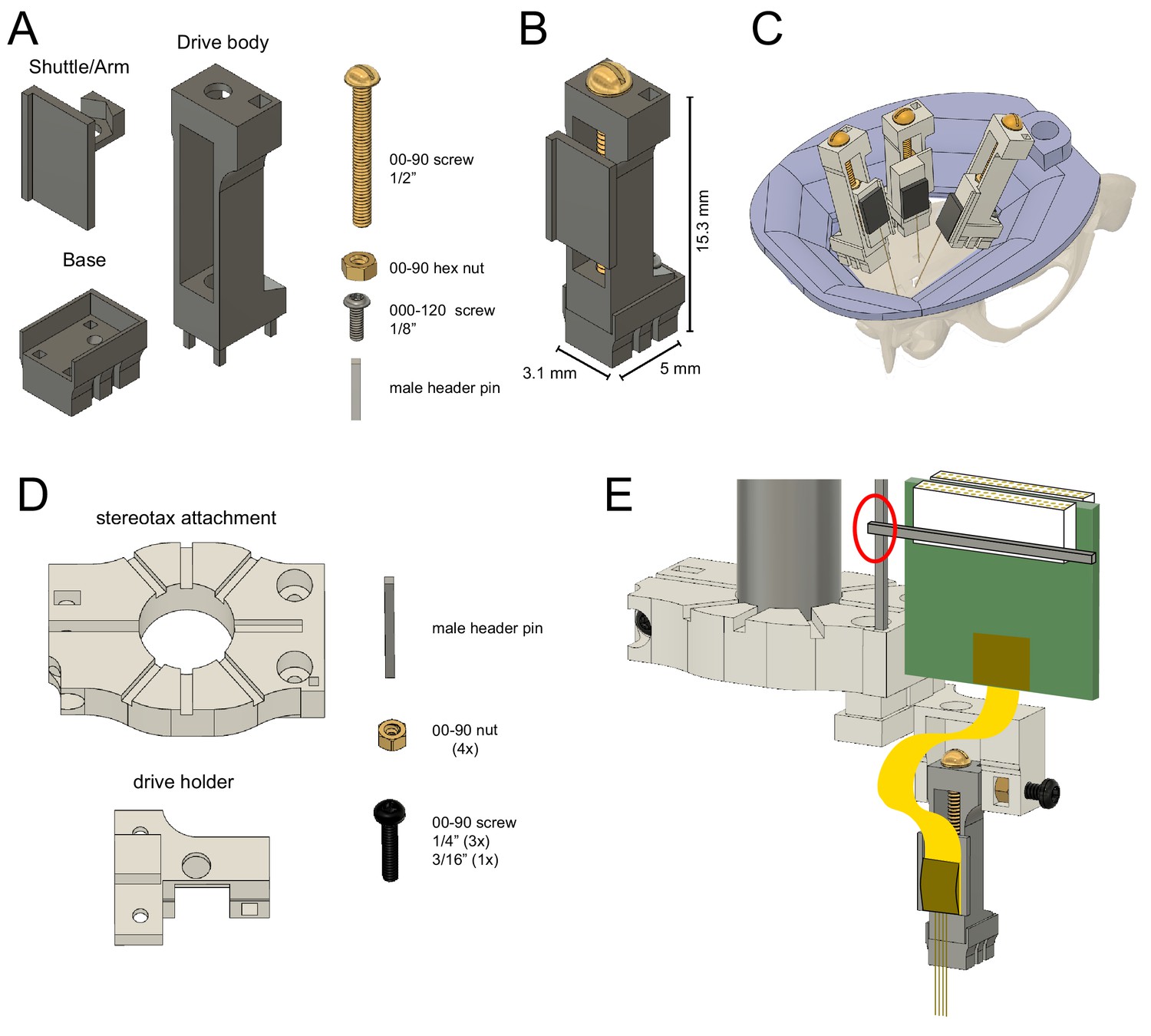
Reusable metal microdrive.
(A) The metal microdrive consists of three main parts: a drive body, a movable arm/shuttle, and a removable base. All components are 3D printed in stainless steel. Additional necessary components are a 00–90, 1/2 ‘brass screw, a 00–90 brass hex nut, a 000–120, 1/8’ stainless steel screw fixing the drive to the base, and a male header pin. (B) The assembled drive with dimensions. (C) Schematic showing three microdrives, with silicon probes attached, implanted in a rat to target hippocampus, medial and lateral entorhinal cortices. 3D printed resin head cap is shown in purple. (D) 3D printed stereotaxic attachment and drive holder together with assembly pieces: male header pin, four 00–90 brass hex nuts, three 00–90, 1/4’ and a 3/16’ stainless steel screw. (E) Stereotaxic attachment with the metal drive assembled, and a probe attached, ready for implantation (red circle highlights the temporary soldering joint for the Omnetics connector). The backend of the silicon probe is attached to the arm using cyanoacrylate glue.
Figure 1—figure supplement 1
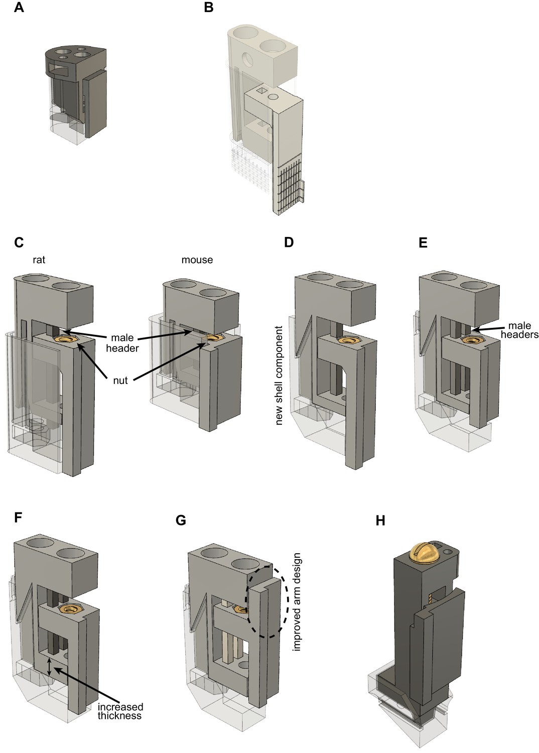
Developmental stages of metal, recoverable microdrive.
Note that the shell component is 50% transparent to aid better visibility of the drive body and shell component connection. All microdrives were printed using Form2 resin-based 3D printer (resin type: clear v4, 50 um layer resolution, Formlabs, MA, USA). (A) Design by Chung et al., 2017. (B) Design by Hiroyuki Miyawaki (https://github.com/Mizuseki-Lab/microdrive). (C) Added nut to arm (reduced metal-to-plastic erosion). (D) Updated shell component to (1) improve stability and (2) reduce footprint from 5.2 × 7.5 mm to 3.2 × 7.5 mm. This enabled bilateral silicon probe implantation in the CA1 region of the hippocampus of rats (Rogers et al., 2021). Reduced weight allowed us to use the same drive in mice (Valero et al., 2021) and rats. (Note, that the shorter mouse microdrive is not supported anymore). (E) Added second male header pin to drive body (further improved stability). (F) Increased thickness of the bottom part of the drive. Drive body became sturdier, less prone to bending. (G) Improved arm design to overcome limitations of resin 3D printing. Most of the arms were not at 90-degree angles. (H) Metal prototype printed in plastic. The small footprint enables double silicon probe implantation in the mouse. Nut is moved from the bottom of the drive to the top. This creates a flat surface at the bottom of the drive body making the shell-drive connection more stable.
Figure 1—figure supplement 2
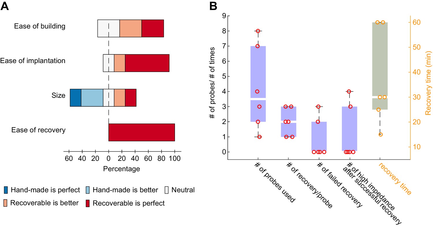
Internal lab survey using recoverable, plastic microdrives.
(A) User feedback based on four criteria: ease of building, ease of implantation, size, ease of recovery (1 to 10 rating scale). The 3D printed microdrive surpasses the manually built drive (Vandecasteele et al., 2012) on every parameter except the size. (B) 24 silicon probes were used with the recoverable plastic microdrive. On average each probe was recovered two times. Out of these 48 recovery attempts five failed only. There were two total losses during recovery and in three cases different number of shanks broke during the recovery process making the recovery partially successful. One major limitation of reusability is the sudden increase in impedance over time (we have to discard 30% of the successfully recovered probes due this reason). Researchers in our lab spend on average 30 min to recover a silicon probe.
Figure 1—video 1
Assembly of metal microdrive.
Figure 1—video 2
Neuropixels probe attachment to metal microdrive.
Figure 2 with 1 supplement
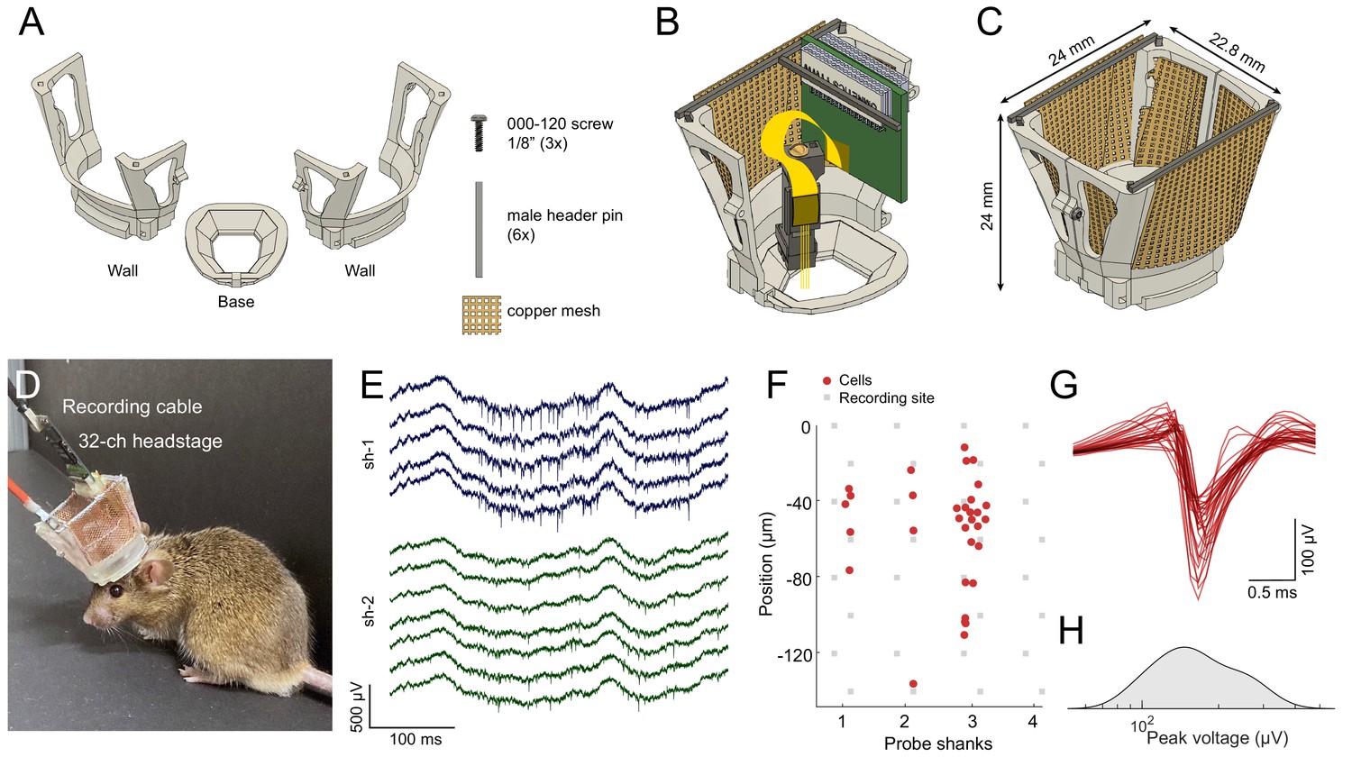
Mouse cap.
(A) The mouse cap consists of three main 3D printed parts: a base, and two side walls. The pieces are assembled with three 000–120, 1/8’ steel screws, six male header pins, and copper mesh. (B) The base with the left side wall attached. Copper mesh was attached in three pieces to the wall, and a male header pin was soldered across the top of the wall. (C) The fully assembled mouse cap. (D) The implanted headgear with preamplifier and recording cable attached. (E) Wide-band extracellular traces recorded from the prelimbic cortex of the implanted mouse shown in (D) using a multi-shank silicon probe during food pellet chasing exploration (sh-1 and sh-2 denote shank 1 and shank 2 of the silicon probe). (F) Well-isolated single units can be recorded in the anterior cingulate cortex using the mouse cap system and microdrive (n = 31 putative single units with a 4-shank probe; same session as in E). The location of the maximum waveform amplitude of each neuron is shown (0 μm corresponds to the location of the topmost channel of the shank). (G) The average spike waveform for each neuron. (H) Distribution of the spike amplitude across the recorded neurons (n = 31).
Figure 2—video 1
Assembly of mouse cap.
Figure 3 with 5 supplements
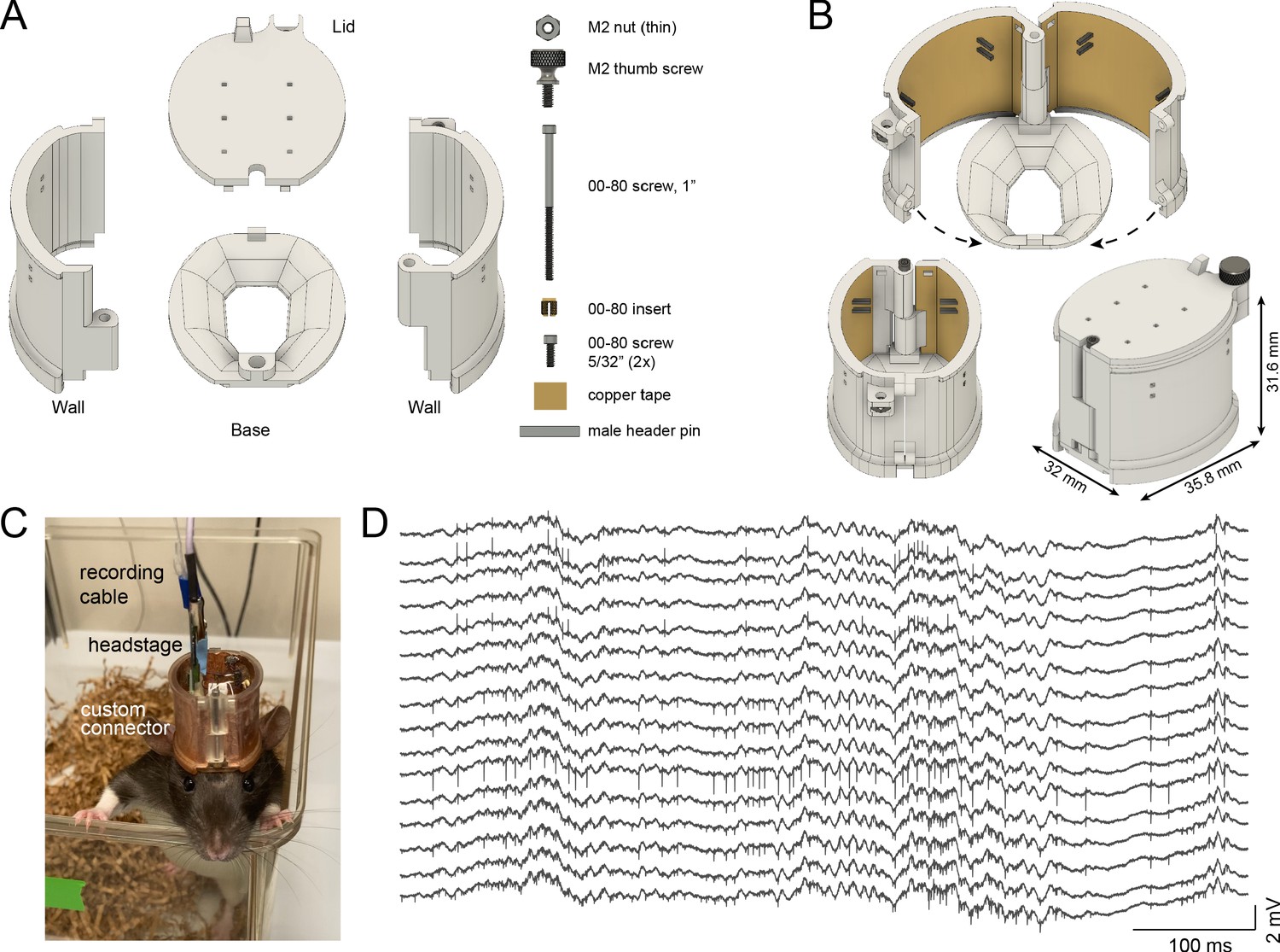
Rat cap.
(A) The rat cap consists of four main 3D printed plastic parts: a base, two side walls, and a lid. To assemble the components, an M2 nut, M2 thumb screw, a 00–80, 1’ screw, a 00–80 insert, and two 00–80, 5/32’ screws are also needed. (B) The assembled rat cap is shown with sidewalls in an open position (top image), closed configuration without (bottom left) and with the lid in place (bottom right). (C) A Long-Evans rat in its home cage with the rat cap, connected to preamplifier and cable. (D) Extracellular traces recorded on post-op day 18 from the same animal.
Figure 3—figure supplement 1
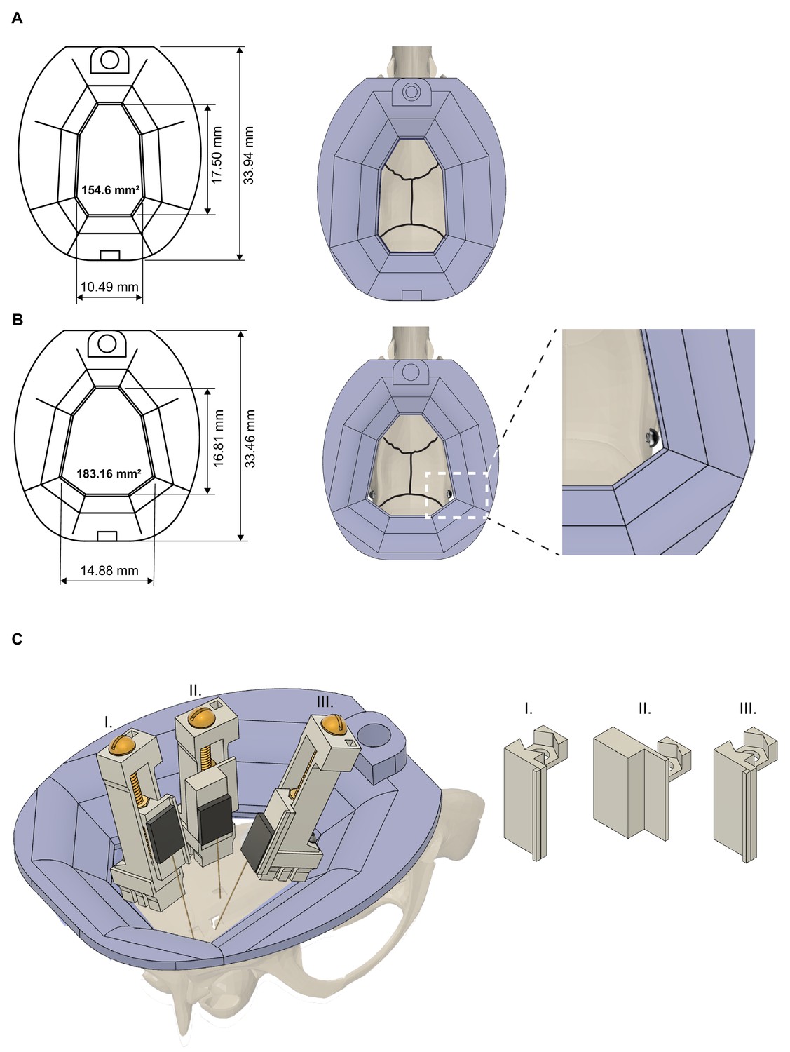
Headcap and microdrive customization.
(A) Rat cap base with dimensions (left) and on top of a rat skull (right). Black lines indicate the sutures of the skull. 3D printed resin base is shown in purple. (B) The base/cap system can be modified to increase the available skull surface (note, that the skull surface was increased to 183.16 mm2 from 154.6 mm2). This modified base is held in place by bone screws implanted in the temporal bone and covered with dental cement (right part). (C) Increasing the inner volume of the cap system and customizing the metal recoverable microdrives enable multiprobe implantations. Schematic showing three microdrives, with silicon probes attached, implanted in a rat to target hippocampus (drive - II), medial and lateral entorhinal cortices (drive - III and I, respectively). Note, the different arm/shuttle designs (right part).
Figure 3—figure supplement 2
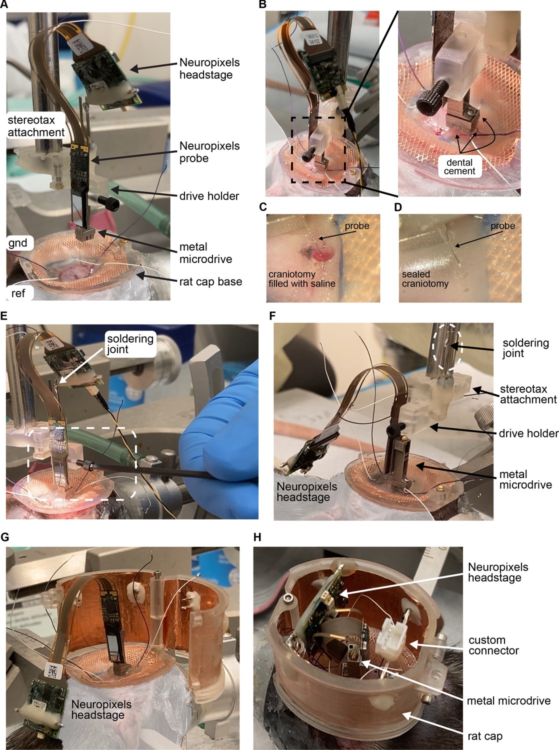
Implantation of Neuropixels probe in a rat using metal microdrive and rat cap system.
(A) The base of the rat cap is attached to the skull. Reference (ref) and ground (gnd) screws are placed over the cerebellum. Neuropixels probe is mounted on a metal microdrive. The microdrive is held by the drive holder and attached to a stereotax arm using the stereotax attachment. For more details, see video: Neuropixels_attachment.mp4. (B) Once the probe is inserted to its final depth (left), the base of the microdrive is cemented to the skull (zoomed in photograph on the right). (C) The surface of the brain is kept wet using saline during probe insertion and during cementing the base of the microdrive. (D) After the base is cemented, the craniotomy is sealed with bone wax. (E) Releasing the drive from the drive holder. Once it is released the stereotax arm is moved upwards. (F) Neuropixels headstage is removed from the male header of the stereotax attachment (soldering joint) and placed on the animals back. (G) The walls of the cap system are attached to the base. Ground and reference wires are soldered to the probe (not shown). (H) The male header of the headstage is secured to the walls. The headstage and its cable are oriented to allow easy access to the screw head of the microdrive. Note, that there is enough room for custom connectors inside the rat cap.
Figure 3—video 1
Assembly of rat cap.
Figure 3—video 2
Assembly of the 3D-printed head cap.
3D-printed head cap is assembled on top of a plastic rat skull. The rat skull with a base is secured in a stereotactic frame (Kopf Instruments). Note the head cap can be assembled completely and closed in less than 2 min.
Figure 3—video 3
Assembly of the copper mesh head cap.
A protective cap is built on top of a plastic rat skull using copper mesh and dental cement. The rat skull with copper mesh is secured in a stereotactic frame (Kopf Instruments). First, the copper mesh is cut and shaped, then it is covered by dental cement for further mechanical support. Note the head cap can be assembled completely in 30 min.
Figure 4 with 2 supplements
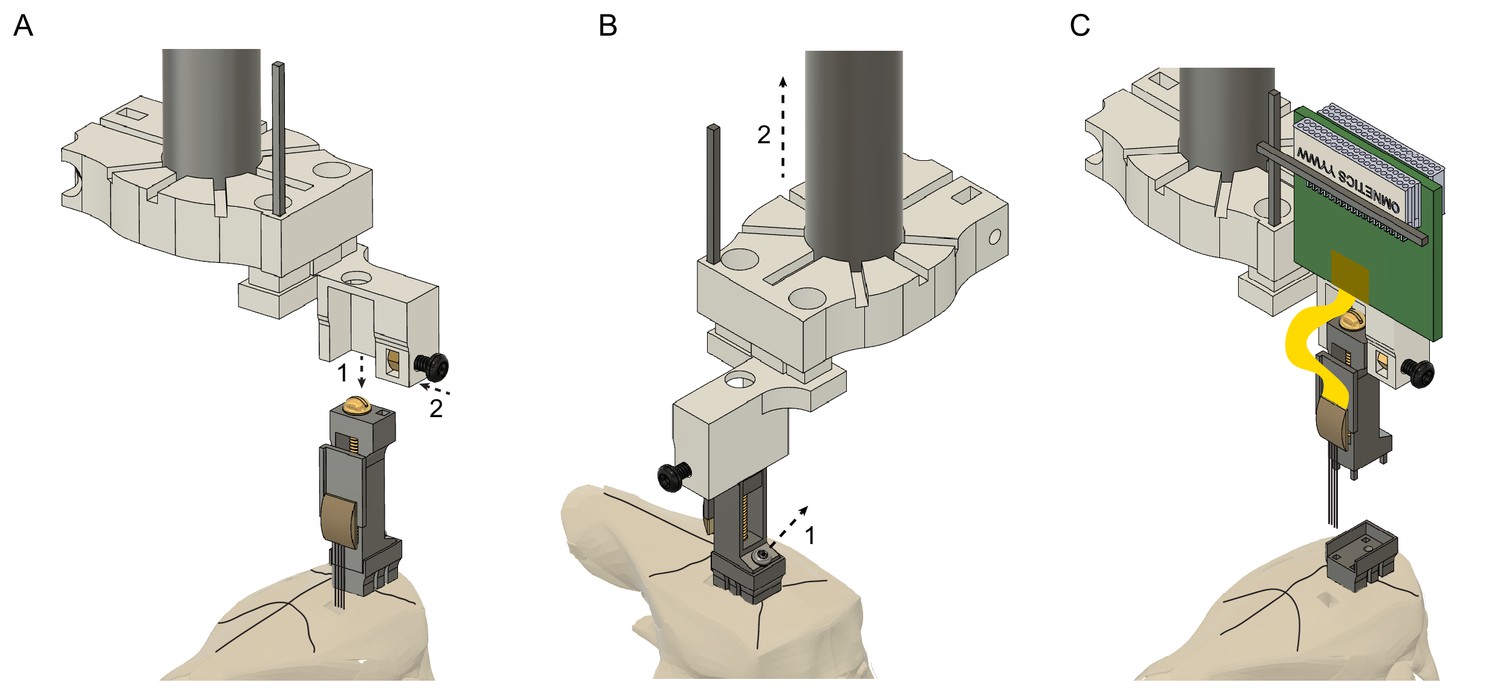
Probe recovery procedure.
(A) The stereotaxic probe holder is attached to the microdrive (step 1) and is fixed with the black screw (step 2). Precise alignment is critical to avoid tissue damage and to prevent breaking the shanks when retracting the probe. (B) The microdrive is detached from the drive-base by removing the 000–120 steel screw (step 1) and moved upwards (step 2). Camera angle rotated 90o. (C) The drive with the attached probe after retracting it from the brain. The drive-base can be reused by cleaning it in chloroform or acetone.
Figure 4—video 1
Silicon probe recovery from a mouse cap.
This video shows how to recover a silicon probe from a mouse cap.
Figure 4—video 2
Silicon probe recovery from a rat cap.
This video shows how to recover a silicon probe from a rat cap.
Figure 5
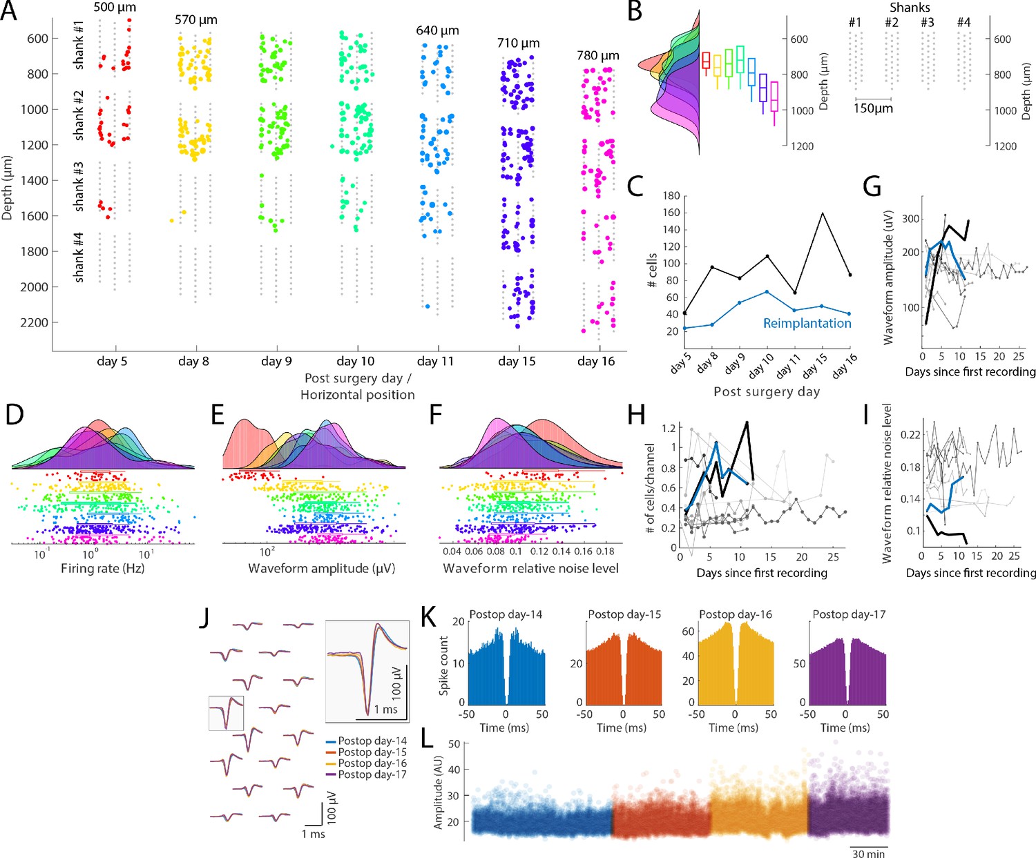
Single unit quantification.
(A) Recordings from the prefrontal cortex at multiple depths across 12 days with a four-shank silicon probe in a mouse (128 channel probe from Diagnostic biochip; P128-5). Individual shanks are displayed as rows across days to better visualize the cells across days. The probe was moved in 70 µm steps to record from a new population of cells across days. Colored dots: position of single cells determined by spike amplitude trilateration. Grey dots: electrode sites. (B) Left: Histogram and boxplots of the distribution of recorded neurons as a function of cortical depth (µm) for each session shown in A. Each colored histogram and corresponding box-plot correspond to the same days shown in A. Right: Probe layout (shanks now shown in a horizontal layout) with the shanks shown with the depth for day 8–10; shanks are spaced by 150 µm. (C) Number of isolated single units across days after the first implantation (black) and after reimplantation of the probe (blue). (D–F) Firing rate (D), waveform amplitude (E; trough-to-peak) and relative noise level (F; waveform std divided by the waveform amplitude). (G–I) Comparison with other control mice and rats (n = 10 subjects), implanted with custom built drives (Vandecasteele et al., 2012), comparing waveform amplitude (G), number of cells/recording site (H) and relative noise level (I; same definition as in panel F). Lines refer to different animal subjects. Thick black line: rat with the metal drive; thick blue line: rat with reimplanted silicon probe mounted on metal drive (panel A-F). Days relative to the first recording session from each animal. (J–L) Neuropixels probe recording, where the same putative interneuron was tracked across four days. (J) Average waveforms (bandpass filtered 300–10000 Hz) of a putative interneuron recorded on16 channels across 4 days (left). The average waveforms recorded at the site with the largest amplitude waveform is highlighted on the right (waveforms are color-coded by recording days). Autocorrelation histograms (K) and spike amplitudes (L; from Kilosort) for the same single unit, color-coded by recording day.
Figure 6
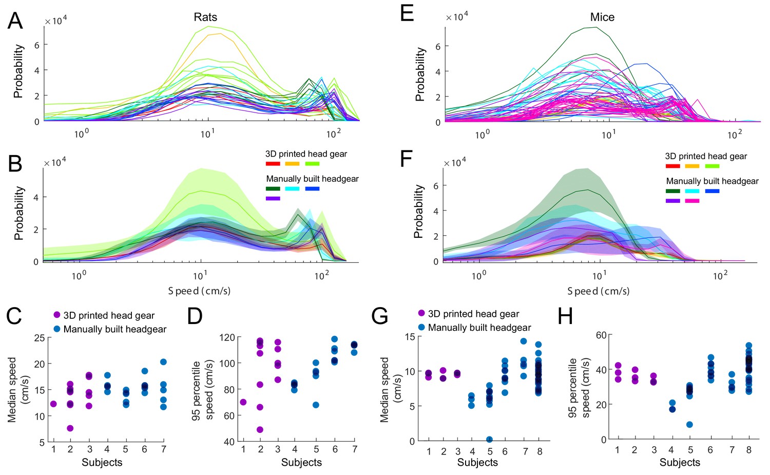
Effect of head gear type on running speed.
Rats and mice implanted with the 3D printed head cap system and subjects with manually built headgear. (A–B) The distribution of running speeds within individual sessions (A) and within individual subjects (B). Three rats implanted with the 3D printed head gear (13 sessions), compared to four subjects with manually built headgear (22 sessions). (C–D) Median (C) and 95 percentiles (D) of the running speed, per sessions. (E–F) The distribution of running speeds within session (E) and average across sessions per subjects (F). Three mice implanted with the 3D printed head gear (nine sessions), compared to five control subjects with manually built headgear (54 sessions). (G–H) Median (G) and 95 percentiles (H) of the running speed, per sessions.
Author response image 1
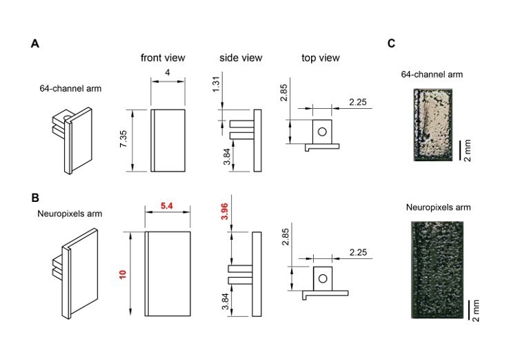
Metal microdrive adapter for Neuropixels probe.
A. Arm design for 64-channel silicon probes. 45o, front, side and top views are shown (from left to right). All dimensions are in mm. B. Changing the overall length (from 7.35 mm to 10 mm) and width (from 4 mm to 5.4 mm) of the 64-channel arm makes our metal microdrive compatible with Neuropixels probe. Note, that only three dimensions of the 64-channel arm were modified (red numbers). 45-degree, front, side and top views are shown (from left to right). All dimensions are in mm. C. Photograph of the different arm designs of the metal, recoverable microdrive (top shows an arm designed for a 64-ch silicon probe, bottom shows an arm designed for Neuropixels probe).
Author response image 2
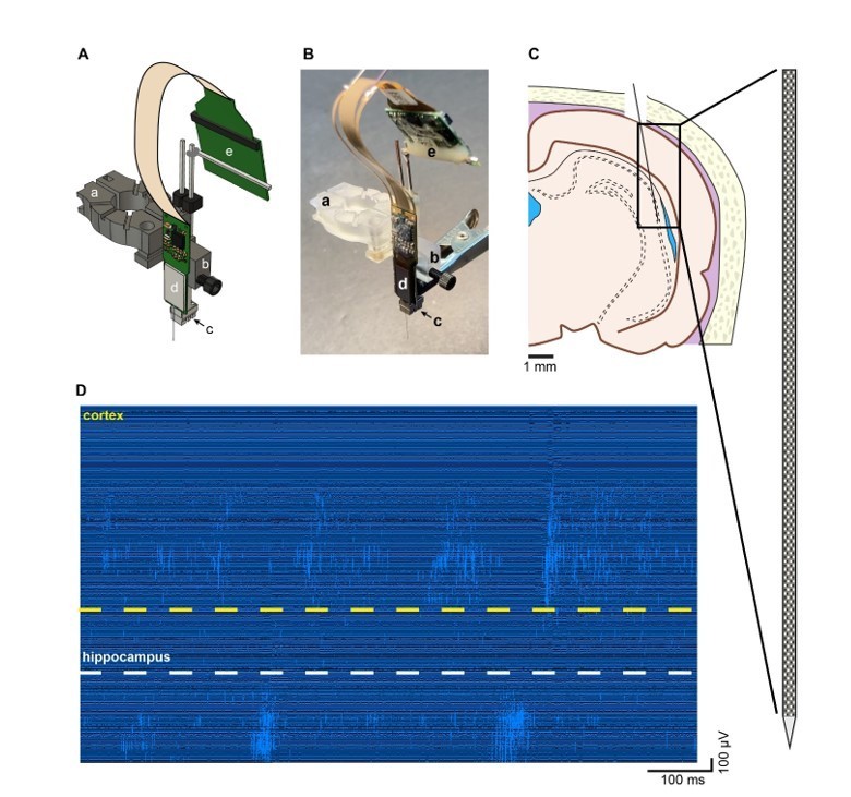
Recording of unit firing with Neuropixels probe attached to a metal microdrive in freely moving rat.
A. Metal microdrive for Neuropixels probe (a – stereotax attachment, b – drive holder, c – metal microdrive, d – Neuropixels probe and e – Neuropixels headstage). B. Photo of Neuropixels probe attached to a metal microdrive (a-e same as in A). C. Location of probe implantation (Bregma – 4.8 mm, mediolateral + 4.6 mm, 11-degree angle). D. High pass filtered traces (1s) from a freely moving rat implanted with Neuropixels probe. Note the single unit activity in the cellular layer of cortex (top) and hippocampus (bottom).
Author response image 3
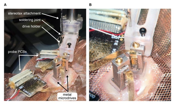
Metal microdrive enables double silicon probe recordings in freely moving mice.
A. Intraoperative photograph of double silicon probe implantation. Note that the metal microdrive on the left had been secured to the skull and the second drive is being implanted using the stereotaxic attachment and drive holder. The probe PCBs are placed on the copper mesh. B. Photograph focused on the metal microdrives.
Tables
Table 1
Summary of microdrive designs used in mice.
| Study/Company | Width (mm) | Length (mm) | Height (mm) | Footprint (mm2) | Weight (g) | Travel distance (mm) | Easy recovery |
|---|---|---|---|---|---|---|---|
| Vandecasteele et al., 2012 | 4.3 | 6.4 | 13 | 27.52 | 0.6 | 8–12 | no |
| Janelia Research Campus | 3.5 | 3.8 | 9 | 13.3 | 0.8 | 5 | no |
| Janelia Research Campus | 2.5 | 3.8 | 10 | 9.5 | 0.5 | 5 | no |
| Cambridge Neurotech | 2.5 | 4 | 9 | 10 | 0.54 | 5 | no |
| Neuronexus | 12.5 | 11.5 | 8.5 | 143.75 | 0.36 | 1 | no |
| NeuroNex MINT | 3.2 | 7.5 | 16 | 24 | 0.67 | 4.8 | yes |
| Chung et al., 2017 | 6.26 | 5.26 | 9 | 32.93 | 0.4 | 2 | yes |
| Juavinett et al., 2019 | 18 | 14 | 20 | 252 | 1 | - | yes |
| Voroslakos et. al. | 3.1 | 5 | 15.3 | 15.5 | 0.87 | 7 | yes |
Key resources table
| Reagent type (species) or resource | Designation | Source or reference | Identifiers | Additional information |
|---|---|---|---|---|
| Other | Recoverable drive (base) | ‘This paper’ – Github repository | Base_v7.step | |
| Other | Recoverable drive (drive) | ‘This paper’ – Github repository | drive_v7.step | |
| Other | Recoverable drive (arm) | ‘This paper’ – Github repository | arm_v7_50 um.step | |
| Other | 00–90 nut | McMaster | 92736A112 | |
| Other | 00–90 screw 1/2’ | McMaster | 92482A235 | |
| Other | 00–120 screw 1/8’ | McMaster | 96710A009 | |
| Other | Male header pin | DigiKey | SAM1067-40-ND | |
| Other | T1 and T2 screwdriver | McMaster | 52995A31 | |
| Other | 00–90 tap | McMaster | 2504A14 | |
| Other | 000–120 tap | McMaster | 2504A15 | |
| Other | stereotax_attachment_metal | ‘This paper’ – Github repository | stereotax_attachment_metal_v7.stl | |
| Other | 00–90 nut | McMaster | 92736A112 | |
| Other | 00–90 screw 1/4’ | McMaster | 93701A005 | |
| Other | Male header pin | DigiKey | SAM1067-40-ND | |
| Other | drive_holder_metal | ‘This paper’ – Github repository | drive_holder_metal_v7.stl | |
| Other | 3 × 00–90 nut | McMaster | 92736A112 | |
| Other | 2 × 00–90 screw 1/4’ | McMaster | 93701A005 | |
| Other | 00–90 screw 3/16’ | McMaster | 93701A003 | |
| Other | 3D printed mouse cap (left wall) | ‘This paper’ – Github repository | left_wall_v12_L11.5 mm_W10.00mm.stl | |
| Other | 3D printed mouse cap (right wall) | ‘This paper’ – Github repository | right_wall_v12_L11.5 mm_W10.00mm.stl | |
| Other | 3D printed mouse cap (base) | ‘This paper’ – Github repository | mouse_base_v12_L11.5 mm_W10.00mm.stl | |
| Other | 3D printed mouse cap (cut out) | ‘This paper’ – Github repository | mouse_hat_copper Mesh_cutOut_v02.stl | |
| Other | 3 × 000–120 screw 1/8’ | McMaster | 96710A001 | |
| Other | Male header pin | DigiKey | SAM1067-40-ND | |
| Other | Copper mesh | Dexmet | 3CU6-050FA | |
| Other | T1 screwdriver | McMaster | 52995A31 | |
| Other | 000–120 tap | McMaster | 2504A15 | |
| Other | 3D printed rat cap (left wall) | ‘This paper’ – Github repository | rat_cap_left_wall_v8.stl | |
| Other | 3D printed rat cap (right wall) | ‘This paper’ – Github repository | rat_cap_right _wall_v8.stl | |
| Other | 3D printed rat cap (base) | ‘This paper’ – Github repository | rat_cap_base_v8.stl | |
| Other | 3D printed rat cap (top) | ‘This paper’ – Github repository | rat_cap_top_v8.stl | |
| Other | 00–80 screw 1’ | McMaster | 92196A060 | |
| Other | 00–80 brass insert | McMaster | 92395A109 | |
| Other | 2 × 00–80 screw 5/32’ | McMaster | 92196A053 | |
| Other | Male header pin | DigiKey | SAM1067-40-ND | |
| Other | Copper tape | McMaster | 76555A724 | |
| Other | M2 × 0.4 thumb screw | McMaster | 99607A256 | |
| Other | M2 × 0.4 thin nut | McMaster | 93935A305 | |
| Other | 00–80 tap | McMaster | 2523A461 | |
| Other | 0.05’ hex key | McMaster | 5497A22 | |
| Other | 3D printer | Formlabs | Form2 | |
| Other | Clear resin | Formlabs | RS-F2-GPCL-04 | |
| Other | Cotton swabs | Fisher Scientific | 19-062-616 | |
| Other | Kimwipes | Kimtech | 34120 | |
| Other | Gelfoam | Fisher Scientific | NC1861013 | |
| Other | Screwdriver | Amazon | B0058ECJIE | |
| Other | 000–120 screw 1/16’ | Antrin Miniature Specialties | AMS120/1B-25 | |
| Other | Burrs for micro drill 0.7 mm | Fine Science Tools | 19008–07 | |
| Chemical compound, drug | C and B Metabond Base 10 ml | Parkell | P16-0116 | |
| Chemical compound, drug | C and B Gold Catalyst | Parkell | P16-0052 | |
| Chemical compound, drug | C and B Metabond Clear Powder | Parkell | P16-0121 | |
| Chemical compound, drug | Unifast Trad Powder Ivory | Pearson Dental | G05-1224 | |
| Chemical compound, drug | Unifast Trad Liquid | Pearson Dental | G05-1226 | |
| Chemical compound, drug | Unifast 1:2 Package A2 | Pearson Dental | G05-0037 | |
| Other | Dental LED Light | Aphrodite | AP-016B | |
| Chemical compound, drug | Cyanoacrylate | Loctite | 45208 | |
| Other | Ground/reference wire | Surplus Sales | (WHS) LW-12/36 | |
| Other | Ground/reference wire | Phoenix Wire Inc | 36744MHW - PTFE | |
| Chemical compound, drug | Ultrazyme Enzymatic Cleaner Tablets | Ultrazyme | B000LM0ZYS | |
| Other | Dieffenbach Vessel Clips Straight (rats) | Harvard Apparatus | ST2 72–8815 | |
| Other | Intan USB Eval board | Intan Technologies LLC | C3100 | |
| Other | Intan headstage | Intan Technologies LLC | C3324 and C3325 | |
| Other | Intan cable | Intan Technologies LLC | C3216 |
Additional files
-
Supplementary file 1
Summary of experiments using recoverable microdrive and cap system in rodents.
All animals were implanted with either mouse (M) or rat (R) cap system. The cap system was first tested in a mouse with wire electrodes (M_01) and in a rat without electrophysiology (R_01). After the evaluation of the cap system, we have implanted silicon probes attached to recoverable, plastic microdrives (Plastic recov refers to this microdrive) or flexible probes cemented in place and tested the cap system with electrophysiology in freely moving mice (M_02 – M_04) and in freely moving rats (R_02 – R_06). We used silicon probes from NeuroNexus (Buzsaki-32 NN) and Cambridge Neurotech (ASSY-156 E1 CN). Finally, we evaluated the recoverable, metal microdrive using a Diagnostic Biochips probe (128–5 DB) in a freely moving mouse (M_05) and a Neuropixels probe in a freely moving rat (R_09). All attempted probe recovery was successful except in R_02A (two shanks broke during the acute recordings). The same ASSY-156 E1 (CN) probe was used in R_03 and R_04, but after successful recovery from R_04 the impedance of the contact sites were too high to reimplant this device. A new ASSY-156 E1 probe was used in R_05.
- https://cdn.elifesciences.org/articles/65859/elife-65859-supp1-v2.docx
-
Transparent reporting form
- https://cdn.elifesciences.org/articles/65859/elife-65859-transrepform-v2.docx
Download links
A two-part list of links to download the article, or parts of the article, in various formats.
Downloads (link to download the article as PDF)
Open citations (links to open the citations from this article in various online reference manager services)
Cite this article (links to download the citations from this article in formats compatible with various reference manager tools)
Metal microdrive and head cap system for silicon probe recovery in freely moving rodent
eLife 10:e65859.
https://doi.org/10.7554/eLife.65859


