A morphological transformation in respiratory syncytial virus leads to enhanced complement deposition
- Department of Biomedical Engineering and Center for Science & Engineering of Living Systems (CSELS), Washington University in St. Louis, United States
Figures
Figure 1 with 4 supplements
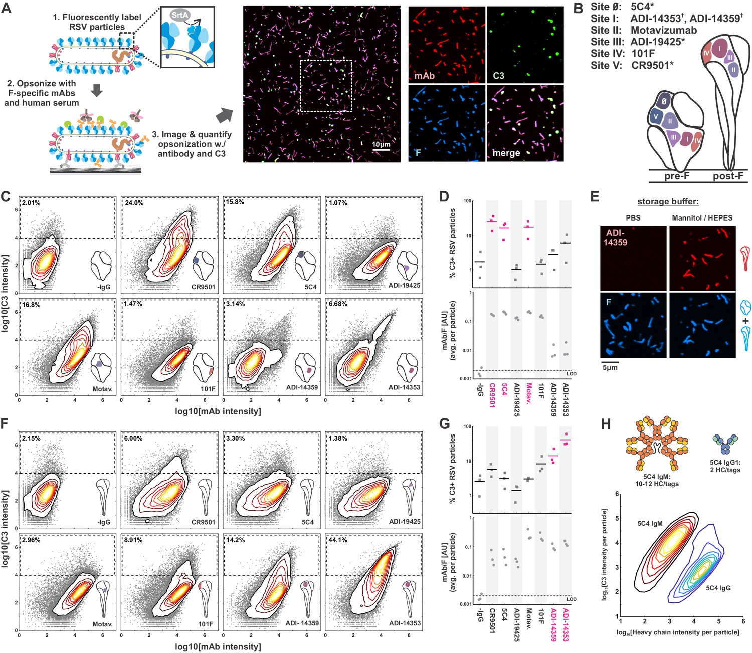
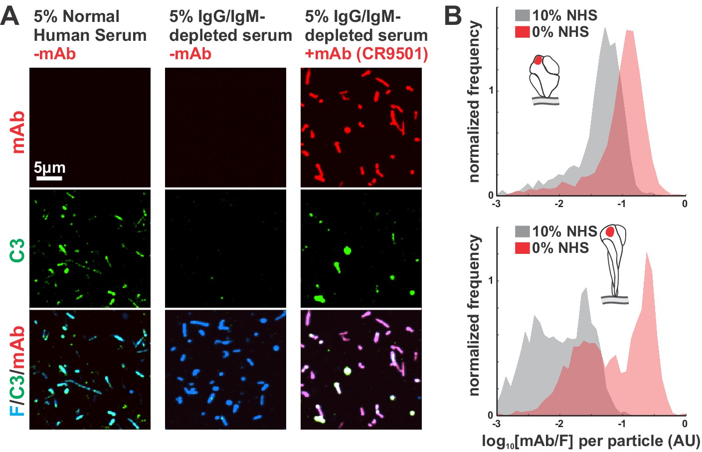
Complement activation and C3 deposition vary across antigenic sites of RSV F.
(A) A fluorescence-based approach to measuring opsonization of RSV particles with mAbs and C3. RSV particles with site-specifically labeled F are immobilized on coverslips and incubated with normal human serum (IgG/IgM-depleted), specific mAbs, and fluorescent C3 prior to imaging. Right: RSV particles opsonized with mAb (CR9501 IgG1 in the image shown) and C3. (B) Antibodies used in this study and their antigenic sites. A ‘*’ denotes mAbs specific to prefusion F while a ‘†’ denotes mAbs specific to postfusion F. (C) Distributions of integrated antibody and C3 intensities on opsonized virus particles with predominantly prefusion F. Gray points indicate data for individual virus particles. Dashed regions indicate criteria for C3-positive particles. Data is combined from three biological replicates. (D) Top: Data from C, plotted as percentage of C3-positive RSV particles, defined by integrated C3 intensities > 104. Points show results from three biological replicates with the mean across the replicates shown as a line. Antibodies determined to be activators of the classical pathway (>10% C3-positive particles) are shown in magenta. Bottom: Plot of average mAb:F intensity per RSV particle across the same antibodies and replicates as in the plots above. (E) Conversion of pre-F to post-F on RSV filaments via ~24 hr incubation in buffer with low ionic strength but balanced osmolarity. Post-F is detected using the site I-directed mAb ADI-14359. Images are displayed at matching contrast levels. (F) and (G): Results corresponding to C and D but for RSV particles containing predominantly post-F. (H) Comparison of C3 deposition by IgM and IgG1 antibodies. Top: Schematic of antibodies based on 5C4. The antibodies contain matching light chains and VH domains coupled to the human heavy chain μ (for IgM), or a human IgG1 Fc. IgM is additionally co-expressed with a J chain plasmid. All heavy chains contain a c-terminal ybbR tag for site-specific conjugation of a fluorophore for quantification of bound antibody. Bottom: Contour plots showing distributions of C3 and IgM/IgG1 heavy chains per RSV particle, based on fluorescence intensities. The IgM distribution is determined from 317594 RSV particles; the IgG distribution is determined from 126372 RSV particles. See also Figure 1—source data 1.
-
Figure 1—source data 1
Matlab code and data for Figure 1, Figure 1—figure supplement 1, Figure 1—figure supplement 2, Figure 1—figure supplement 3, and Figure 1—figure supplement 4.
- https://cdn.elifesciences.org/articles/70575/elife-70575-fig1-data1-v1.zip
Figure 1—figure supplement 1
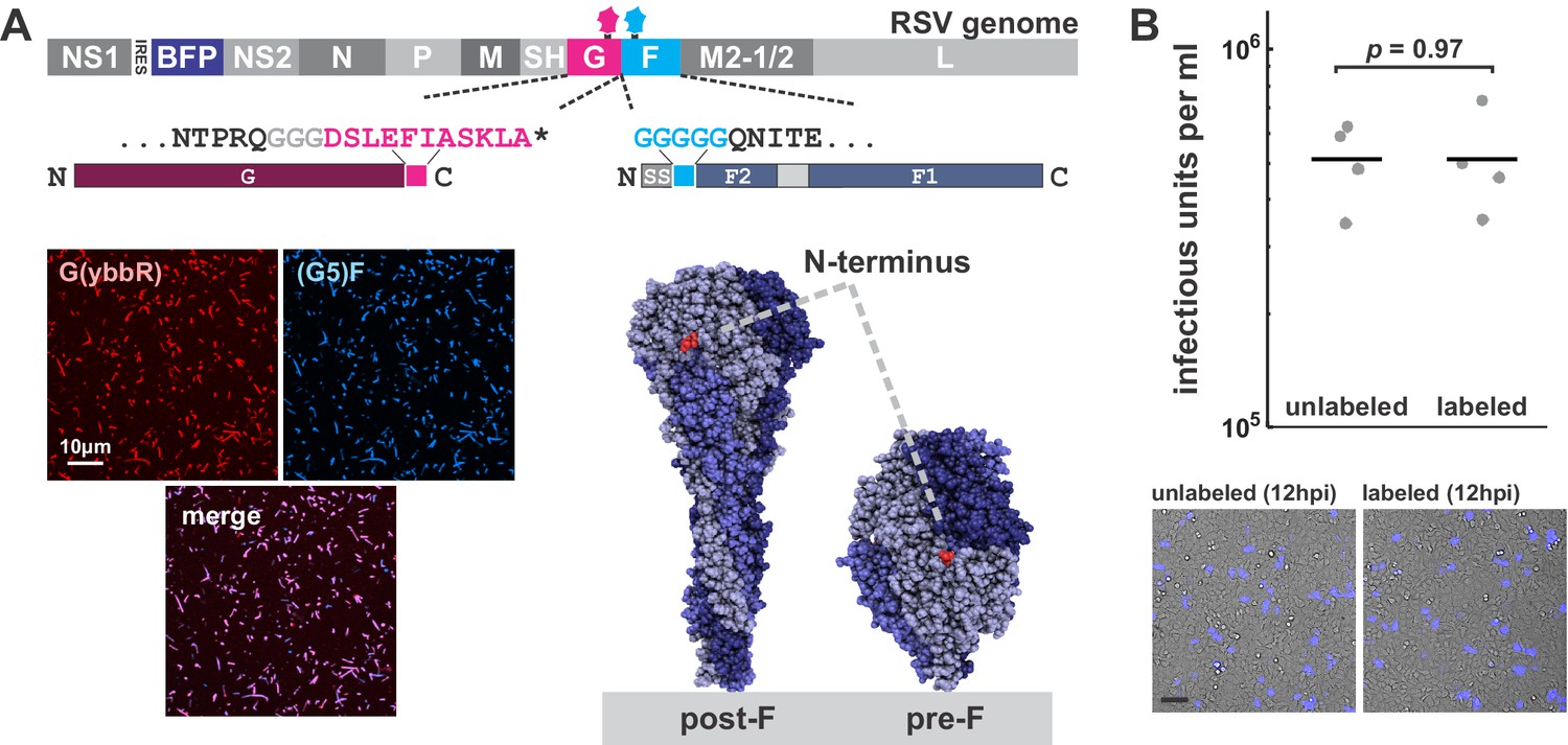
A fluorescence imaging-based approach to study complement deposition on RSV.
(A) Top: Schematic of the RSV genome highlighting specific modifications: an mTagBFP2 reporter expressed from an IRES following NS1, and tags for site-specific labeling on G (C-terminal ybbR tag) and F (N-terminal Sortase A [SrtA] tag). Bottom left: Images of RSV particles with labeled G and F. Bottom right: Structures of pre- and postfusion F (PDB IDs 4MMU and 3RRR, respectively) highlighting the location of the N-terminal tag, which remains accessible for labeling on both structures. (B) Comparison of RSV infectivity with and without fluorescent modifications to F. Infected cells were quantified at 12 hpi by counting cells expressing the BFP reporter (representative images in lower panels; scale bar = 100 μm). RSV particles quantified were those shed into the culture media during a 2 hr incubation and does not include cell-associated virus. Points show results from individual replicates; lines show mean values. p-Value determined by a two-sample t-test.
Figure 1—figure supplement 2
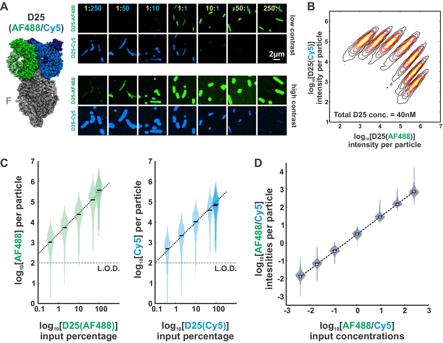
Determining the linearity of fluorescence measurements.
(A) Left: RSV F bound in a 3:3 ratio with the D25 Fab (PDB ID 4JHW). Coloring of the D25 Fab indicates the two populations used for these experiments: one labeled 1:1 (Fab:dye) with AF488 and a second labeled 1:1 with Sulfo-Cy5 (‘Cy5’). Right: Representative images of RSV particles labeled using different ratios AF488/Cy5-labeled D25 Fab. ‘High contrast’ images have been adjusted to show particles with weaker fluorescence (equal adjustment for each image). The total D25 concentration is held constant at 40 nM. (B) Distributions of particle intensities for the seven different ratios of AF488/Cy5-D25 indicated in (A). (C) Data from (B), with distributions of D25(AF488) and D25(Cy5) intensities plotted separately against the input percentage of each fluorophore relative to total D25. Black bars indicate median values. The dotted black line (slope of 1) indicates a linear relationship. The limit of detection (‘LOD’) is approximately determined from the median intensity of a sample with no Fabs (i.e. background fluorescence). (D) Distributions of relative fluorescence intensities (AF488/Cy5) plotted against the relative input concentrations. Squares and dashed lines indicate a linear relationship. Intensity data is the same as shown in (B) and (C). See also Figure 1—source data 1.
Figure 1—figure supplement 3
Estimating the efficiency of enzymatic labeling.
(A) Procedure for calibrating the relative intensities of AF488 and Sulfo-Cy5 (‘Cy5’) dyes. Distributions to the left show data for RSV particles bound with saturating concentrations of D25(AF488) and D25(Cy5) at equimolar ratios. An equivalent Cy5 intensity (‘Cy5 eg.’) is then determined by normalizing the Cy5 intensity distribution such that it has the same median value as the AF488 distribution (shown in the panels to the right). (B) Comparison between RSV F dually labeled with Cy5 via Sortase A (SrtA) and with AF488 via bound D25 Fab (incubated at 400 nM to saturate binding). Cy5 intensities are given as equivalent values, as determined in A. Comparisons of intensities indicate ~0.93 Cy5 molecules per molecule of AF488, or a labeling efficiency of ~93%. (C) Comparisons of separate populations of RSV F labeled either with Cy5 via SrtA or with Cy5 via D25 Fab (bound at 400 nM). Enzymatically labeled RSV particles are from the same two replicates plotted in B. See also Figure 1—source data 1.
Figure 1—figure supplement 4
Effects of IgG/IgM depletion on complement deposition and binding of RSV-specific mAbs.
(A) Comparison of C3 deposition in complete normal human serum (5%) and IgG/IgM-depleted serum (5%), with and without supplemental mAbs. Images are displayed at matching contrast across each channel. (B) Antibody competition between fluorescent mAbs and polyclonal antibodies from normal human serum without IgG/IgM depletion. Results are shown as distributions of integrated mAb intensity normalized to integrated F intensity per RSV particle. Top: Comparison of binding by pre-F-specific mAb 5C4. Bottom: Comparison of binding by post-F-specific mAb ADI-14359 for viruses converted to post-F form by incubation with low ionic strength buffer (see also Figure 1B and E). See also Figure 1—source data 1.
Figure 2

Complement activation and C1q binding varies with Fc position.
(A) Modeling Fc positions for F-specific mAbs. Structures for RSV F (or portions thereof) with bound antibodies (PDB IDs 6OE4, 5W23, 4ZYP, 3IXT, 6APD, 6APB, and 3O45) were aligned with human IgG1 (PDB ID 1HZH) to determine representative locations accessible to antibody Fc regions (indicated by dashed outline). Distances from the viral membrane range from ~1 nm (101F) to ~18 nm (CR9501, ADI-14359). (B) C1q binding to predominantly pre-F RSV particles opsonized with different antibodies. The top plot shows the percentage of C1q+ particles, defined as those with a total intensity of anti-C1qA antibody >103. The bottom plot shows the intensity of anti-F mAb for each condition. Individual points represent values for three biological replicates. Antibodies determined to activate complement from pre-F antigens (Figure 1) are shown in magenta. (C) Distributions of anti-F mAb intensities (horizontal axis) and anti-C1qA antibody intensities (vertical axis) for different anti-F mAbs bound to pre-F particles. Particles within the dashed rectangles indicate those that are C1q-positive, and the percentage of these particles is indicated in the upper left. Distributions are combined from the same three biological replicates represented in B. See also Figure 2—source data 1.
-
Figure 2—source data 1
Matlab code and data for Figure 2.
- https://cdn.elifesciences.org/articles/70575/elife-70575-fig2-data1-v1.zip
Figure 3

CD55 is packaged into RSV particles and increases thresholds for C3 opsonization.
(A) Images of RSV particles with enzymatically labeled F and CD55 or CD46 labeled via fluorescent antibodies. Panels show representative images of virus released from wildtype (wt) A549 cells and CD55 or CD46 knockout (KO) cells, displayed at matching contrast levels. Scale bar = 5 μm. (B) Histograms showing distributions of antibody intensities per RSV particle for wt and KO cell lines. (C) Comparison of C3 deposition on viruses raised in wt cells (open circles) or CD55 KO cells (closed circles) using three different F-specific antibodies and a negative control. Black markers show average values across four biological replicates. Individual replicates are shown in gray. Connecting lines indicate samples that were prepared in parallel, using virus collected from separate batches of wt and CD55 KO cells. p-Values are determined using a paired-sample t-test. (D) Similar plot as in C, but for data obtained from CD46 KO cells. (E) Distributions of antibody and C3 intensities for serial dilutions of CR9501 IgG1. Panels in the top row show results for viruses from CD55 KO cells, while panels from the bottom row show results for viruses from wt cells. The region indicated by the dashed line represents the threshold for C3-positive particles. Percentages in the upper left corners indicate the percentage of C3-postiive particles. Data is combined from three biological replicates. (F) Data from E plotted as percentage C3-positive particles per condition. Bars indicate mean values and points show individual replicates. * indicates p < 0.05 calculated using a two-sample t-test. See also Figure 3—source data 1.
-
Figure 3—source data 1
Matlab code and data for Figure 3.
- https://cdn.elifesciences.org/articles/70575/elife-70575-fig3-data1-v1.zip
Figure 4
Globular particles are preferentially and rapidly opsonized with C3 and C4.
(A) RSV particles opsonized with antibody (CR9501 IgG1) and C3. White arrows in merged panel indicate globular particles with high levels of C3. (B) Comparison of particle aspect ratios across RSV particles that do (green boxes) or do not (gray boxes) show opsonization with C3. Boxes indicate 25th–75th percentiles and points show median values for three biological replicates. Analysis is limited to particles with an area larger than 100 pixels, where morphology can be determined from diffraction-limited images. p-Values are determined based on median values using a paired sample t-test. (C) Time series of C4 accumulation on RSV particles. White arrows indicate first detectable accumulation of C4. (D) C4 accumulation on RSV particles over time, categorized by particle morphology. Data to the left shows C4 accumulation on 742 globular particles; data on the right show C4 accumulation for 607 filamentous particles. In both plots, rows show C4 data for individual particles from 0 to 30 min, sorted from top to bottom according to total C4 accumulation. (E) Data from D, plotted by grouping particles within percentile intervals from 0% to 10%, 10% to 20%, etc. and averaging C4 accumulation in each group. (F) Sample images of globular (top) and filamentous (bottom) RSV particles. Displayed images are sampled at 4 min intervals beginning from 2 min after the addition of serum and complement components (scale bar = 1 μm). See also Figure 4—source data 1.
-
Figure 4—source data 1
Matlab code and data for Figure 4.
- https://cdn.elifesciences.org/articles/70575/elife-70575-fig4-data1-v1.zip
Figure 5 with 1 supplement
Globular particles are enriched in post-F, but remain sensitive to pre-F-mediated complement deposition.
(A) Three-color labeling strategy to detect total F (via enzymatic labeling with Sortase A [SrtA]), post-F (via the post-F-specific mAb ADI-14359), and pre-F (via the pre-F-specific mAb 5C4). Fluorescence images show RSV particles labeled to indicate pre-F, post-F, and total F on the virion surface. (B) Experimental approach to determine effects of aging on RSV particles. (C) Distributions of pre-F and post-F intensities for virus aged 2 hr at 37°C (left) or 24 hr at 37°C (right). Data is combined from three biological replicates. Region inside the dashed lines defines criteria for post-F-positive particles. (D) Percentage of post-F-positive particles (left) and filamentous particles (right) after 2 and 24 hr aging. Post-F-positive particles are defined as those within the dashed lines in C. Filamentous particles are defined as those with length >1 μm and aspect ratio (L/W) > 2. Gray lines show results from paired biological replicates; black lines show average values. p-Values are determined using a paired sample t-test. (E) Distributions of C3 and mAb intensities per RSV particle in the absence of mAb (‘-IgG’) or in the presence of ADI-14359 or CR9501. The top row shows results for particles aged for a total duration of 2 hr at 37°C (i.e. during budding from A549 cells); the bottom row shows particles aged for a total duration of 24 hr at 37°C following collection at 2 hr. Particles within the dashed rectangles indicate those that are C3-positive, and the percentage of these particles is indicated in the upper left. Distributions are combined from three biological replicates. (F) Left: Percentage of C3-positive particles following aging at 37°C for 2 hr (open circles) or 24 hr (filled circles). Black markers give average values for three biological replicates; individual replicates are shown in gray. Right: Mean mAb/F intensities per particle for the same datasets plotted to the left. p-Values determined using a paired-sample t-test. See also Figure 5—source data 1.
-
Figure 5—source data 1
Matlab code and data for Figure 5.
- https://cdn.elifesciences.org/articles/70575/elife-70575-fig5-data1-v1.zip
Figure 5—figure supplement 1
Pre-F and post-F containing RSV particles occur naturally in cell culture.
Images of live RSV-infected A549 cells at 48 hpi showing mTagBFP2 reporter (indicating infected cells) along with pre- and postfusion F, labeled using 5C4 (Alexa Fluor 488) and ADI-14359 (Alexa Fluor 555) mAbs added directly to culture medium. Images are displayed as maximum intensity projections from a three-dimensional confocal stack. Post-F enriched particles with globular morphology are present on the surface of both RSV-infected and neighboring uninfected cells.
Figure 6 with 3 supplements

Membrane detachment from the viral matrix increases complement activation.
(A) Process for detaching the RSV matrix from the viral membrane using osmotic swelling. Fluorescence images show details of the transformation, with t = 0 s approximately corresponding to the addition of low osmolarity buffer. (B) Left: C1q binding per RSV particle, with (filled circles) and without (open circles) osmotic swelling. Black markers indicate averages across four biological replicates. Individual replicates are shown in gray, with connecting lines indicating paired replicates. C1q intensity is measured using a C1qA-specific antibody conjugated with Alexa Fluor 488. Right: Average mAb intensity per particle for the same experiments plotted to the left. p-Values determined using a paired-sample t-test. (C) Percent C3-positive RSV particles with (filled circles) and without (open circles) osmotic swelling. Plots to the left are for predominantly pre-F particles; plots to the right are for predominantly post-F particles. Black markers indicate averages of four biological replicates (individual replicates are color-coded according to the mAb’s antigenic site). p-Values determined using a paired-sample t-test. (D) Percent C3-positive RSV particles with (filled circles) and without (open circles) osmotic swelling across different dilutions of 5C4 IgM. Black lines indicate averages across individual biological replicates (shown in gray). p-Values determined using a paired-sample t-test. See also Figure 6—source data 1.
-
Figure 6—source data 1
Matlab code and data for Figure 6, Figure 6—figure supplement 1, and Figure 6—figure supplement 2.
- https://cdn.elifesciences.org/articles/70575/elife-70575-fig6-data1-v1.zip
Figure 6—figure supplement 1
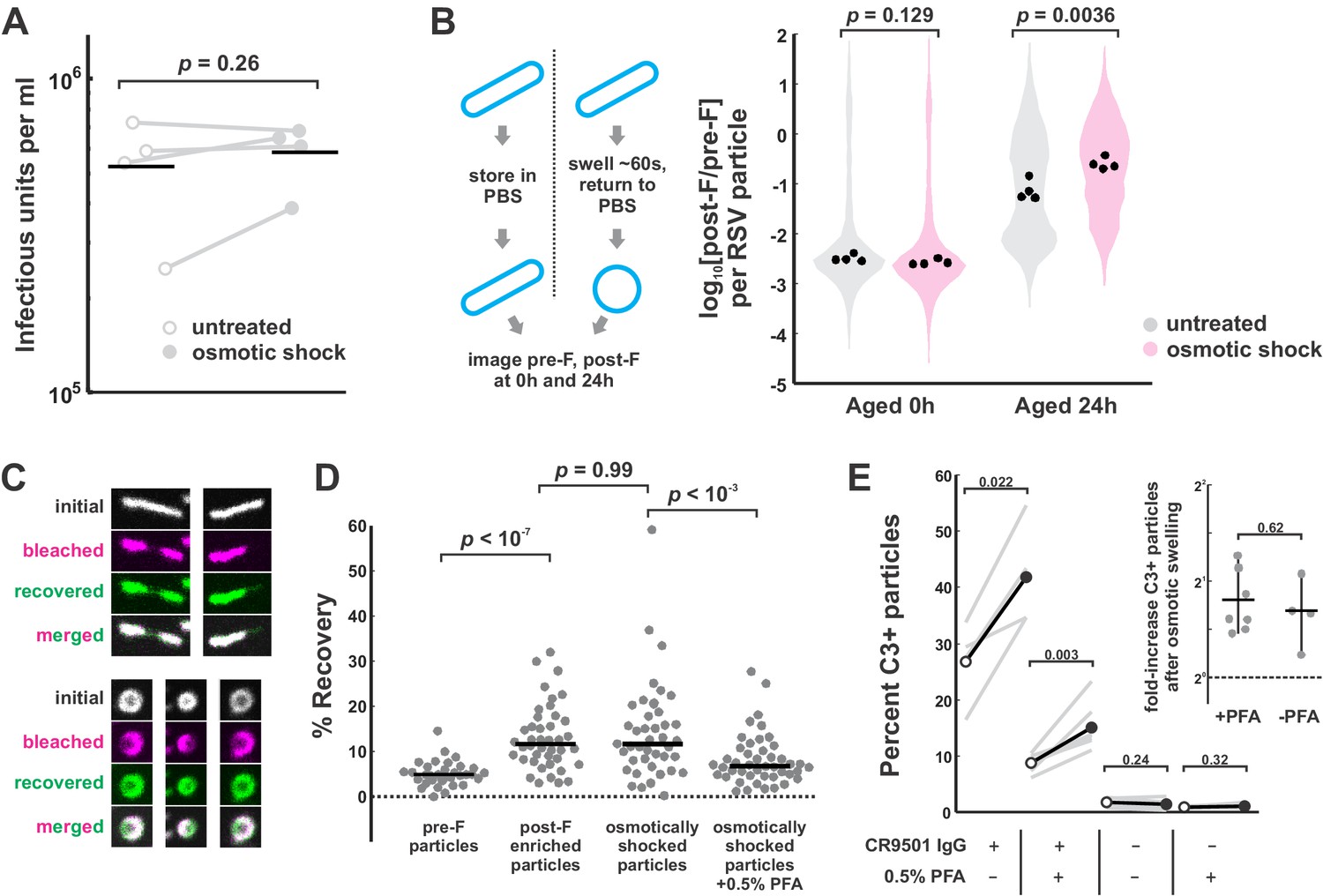
Osmotic swelling detaches the RSV matrix from the viral membrane with no loss of infectivity.
(A) Comparison of infectivity (quantified as single-round infectious units per ml) of virus shed from A549 cells during a 2 hr period starting at 60 hpi. RSV samples were divided into control (untreated) and experimental groups (osmotic shock), and used to infect confluent monolayers of A549 cells. Infected cells were quantified at 12 hpi by counting cells expressing the BFP reporter. The experiment does not account for RSV particles that remain cell-associated. p-Values determined using a paired-sample t-test. (B) Left: Experimental design to compare pre-F stability in particles with and without induced matrix detachment. Right: Comparison of pre-F stability on untreated particles (gray) and particles subjected to brief osmotic swelling (magenta) to detach the viral matrix. Distributions show the ratio of post-F (ADI-14353) to pre-F (5C4) across particles from four biological replicates. Black points show median values for each individual replicate. p-Values are determined from a two-sample t-test. (C) Images of photobleached/recovered RSV filaments (top) and spheres (bottom), where spheres are obtained through osmotic swelling. Magenta images show virus particles immediately after bleaching; green images show viruses after 20 s of recovery. (D) Quantification of fluorescence recovery of different RSV particle subsets. Points represent individual viruses and black lines represent median values. p-Values are determined using a two-sample KS test. (E) C3 deposition on RSV particles with (filled circles) and without (open circles) osmotic swelling. Gray lines connecting points indicate paired biological replicates. Black lines indicate average values across biological replicates. Fixation with 0.5% PFA was used to restrict antigen mobility, as shown in D. p-Values determined using a paired-sample t-test. Inset: Fold-change in percent C3-positive particles following osmotic swelling, with and without treatment with 0.5% PFA. p-Values determined using a two-sample t-test. See also Figure 6—source data 1.
Figure 6—figure supplement 2
C3 deposition on RSV particles increases with decreasing particle curvature.
(A) Model of an idealized morphological transformation in RSV. Detachment of the viral matrix leads to the rounding of virus particles. Mean curvature can be predicted from particle geometry and the constraint that surface area is conserved during the shape transformation. (B) Left: Plot of the relationships in A showing mean curvature vs. particle surface area. Schematics of viral filaments/spheres are drawn approximately to scale in blue. Right: Relationships from the left plot, displayed as the predicted ratio of filament mean curvature to sphere mean curvature as a function of surface area. (C) Top: Data for C3 deposition driven by four activating antibodies (CR9501, 5C4, and Motavizumab for pre-F and ADI-14359 for post-F) and a negative control with no antibody. Black points/bars show median/25th–75th percentile data for viruses preserved in the filamentous state and magenta points/bars show data for osmotically swollen viruses. p-Values determined using a two-sample t-test. Bottom: Same data as in the top plots, displayed as fold-increase in median C3/F for spherical vs. filamentous morphological states. See also Figure 6—source data 1.
Figure 6—figure supplement 3
A conceptual model for the changing surface of RSV.
RSV particles emerge from cells as filaments. Detachment of the viral matrix (either spontaneously or through physical perturbations) alters virus morphology, transforming particles into globular shapes. Particles with globular morphology favor the attachment of C1 via the enhanced formation of antibody hexamers (not shown). Detachment of the viral matrix is also linked to conversion of pre-F to post-F. Collectively, these changes in the molecular surface of RSV particles may shape downstream immune cell responses.
Figure 7
RSV curvature constrains docking of IgG hexamers.
(A) Schematic of RSV F on virion surfaces with varying curvature (left) and a structure (PDB ID 1HZH) and simplified model of an IgG1 hexamer (right). The curved membrane, F, and hexameric IgG are drawn approximately to scale relative to the 50 nm scale bar. (B) Snapshots of simulations showing an accepted hexamer configuration (left) and an unaccepted configuration (right) on a surface with 50 nm radius. For clarity, only Fabs facing the surface are shown. (C) Model predictions for the fraction of IgG hexamer configurations that are compatible with surfaces of different curvature (plotted as filament radius on the horizontal axis). Simulations consider different lattice organization (hexagonal, square-diagonal, and square-upright), as well as different epitope spacing (d), as measured in the plane of the membrane. The shaded region in the plots corresponds to the expected range of curvatures observed for filamentous RSV particles. (D) Left: A proposed model connecting membrane curvature to effective epitope density. Higher curvatures (corresponding to smaller values of the radius, a) result in greater splay of F trimers in the membrane, increasing the distance between membrane-distal epitopes (d’). Right: Simulations comparing IgG hexamer docking to epitopes above the membrane (h = 12 nm, as in C; dashed lines), or within the plane of the membrane (h = 0 nm; solid lines). This model does not account for possible steric hindrance that could arise in the case of membrane-proximal epitopes. See also Figure 7—source data 1 and Figure 7—source code 1.
-
Figure 7—source code 1
Matlab code for running simulations for Figure 7.
- https://cdn.elifesciences.org/articles/70575/elife-70575-fig7-code1-v1.zip
-
Figure 7—source data 1
Matlab code and data for Figure 7.
- https://cdn.elifesciences.org/articles/70575/elife-70575-fig7-data1-v1.zip
Tables
Key resources table
| Reagent type (species) or resource | Designation | Source or reference | Identifiers | Additional information |
|---|---|---|---|---|
| Cell line (Homo sapiens) | HEK 293T | ATCC | ATCC Cat# CRL-3216, RRID:CVCL_0063 | |
| Cell line (Homo sapiens) | A549 | ATCC | ATCC Cat# CCL-185, RRID:CVCL_0023 | |
| Cell line (Melanochromis auratus) | BHK-21 | ATCC | ATCC Cat# CCL-10, RRID:CVCL_1915 | |
| Strain, strain background (Escherichia coli) | SW102 | NCI Preclinical Repository | Used for BAC recombineering | |
| Recombinant DNA reagent | RSV BAC | BEI Resources | NR-36460 | This BAC has been further modified for this work as described in Materials and methods |
| Recombinant DNA reagent | pA2-Lopt | BEI Resources | NR-36461 | |
| Recombinant DNA reagent | pA2-Nopt | BEI Resources | NR-36462 | |
| Recombinant DNA reagent | pA2-Popt | BEI Resources | NR-36463 | |
| Recombinant DNA reagent | pA2-M2-1opt | BEI Resources | NR-36464 | |
| Recombinant DNA reagent | pCAGGS-T7 RNAP | This work | Plasmid encoding T7 RNAP | |
| Recombinant DNA reagent | pmAb-ADI-14353 HC | This work | Plasmid for expressing recombinant antibody | |
| Recombinant DNA reagent | pmAb-ADI-14353 LC | This work | Plasmid for expressing recombinant antibody | |
| Recombinant DNA reagent | pmAb-ADI-14359 HC | This work | Plasmid for expressing recombinant antibody | |
| Recombinant DNA reagent | pmAb-ADI-14359 HC Fab | This work | Plasmid for expressing recombinant antibody | |
| Recombinant DNA reagent | pmAb-ADI-14359 LC | This work | Plasmid for expressing recombinant antibody | |
| Recombinant DNA reagent | pmAb-ADI-19425 HC | This work | Plasmid for expressing recombinant antibody | |
| Recombinant DNA reagent | pmAb-ADI-19425 LC | This work | Plasmid for expressing recombinant antibody | |
| Recombinant DNA reagent | pmAb-5C4 HC (IgG1) | This work | Plasmid for expressing recombinant antibody | |
| Recombinant DNA reagent | pmAb-5C4 HC (IgM) | This work | Plasmid for expressing recombinant antibody | |
| Recombinant DNA reagent | pmAb-5C4 LC | This work | Plasmid for expressing recombinant antibody | |
| Recombinant DNA reagent | pmAb-CR9501 HC | This work | Plasmid for expressing recombinant antibody | |
| Recombinant DNA reagent | pmAb-CR9501 LC | This work | Plasmid for expressing recombinant antibody | |
| Recombinant DNA reagent | pmAb-Motavizumab HC | This work | Plasmid for expressing recombinant antibody | |
| Recombinant DNA reagent | pmAb-Motavizumab LC | This work | Plasmid for expressing recombinant antibody | |
| Recombinant DNA reagent | pmAb-101F HC | This work | Plasmid for expressing recombinant antibody | |
| Recombinant DNA reagent | pmAb-101F LC | This work | Plasmid for expressing recombinant antibody | |
| Recombinant DNA reagent | pmAb-D25 HC Fab | This work | Plasmid for expressing recombinant antibody | |
| Recombinant DNA reagent | pmAb-D25 LC | This work | Plasmid for expressing recombinant antibody | |
| Recombinant DNA reagent | pmAb-3D3 HC | This work | Plasmid for expressing recombinant antibody | |
| Recombinant DNA reagent | pmAb-3D3 LC | This work | Plasmid for expressing recombinant antibody | |
| Recombinant DNA reagent | pmAb-J chain | This work | Plasmid for expressing recombinant antibody | |
| Recombinant DNA reagent | Lenti CRISPRv2 | Addgene | Ref. [70] | |
| Biological sample (Homo sapiens) | IgG/IgM-depleted normal human serum | Pelfreeze | 34,014 | |
| Biological sample (Homo sapiens) | C3 | Complement Technology, Inc | A113 | |
| Biological sample (Homo sapiens) | C4 | Complement Technology, Inc | A105 | |
| Biological sample (Homo sapiens) | C1 | Complement Technology, Inc | A098 | |
| Antibody | Mouse anti-CD46 monoclonal (TRA-2–10) | BioLegend | BioLegend Cat# 352404, RRID:AB_10900243 | IF (1:500) |
| Antibody | Mouse anti-CD55 monoclonal (JS11) | BioLegend | BioLegend Cat# 311301, RRID:AB_314858 | IF (1:500) |
| Antibody | Mouse anti-C1q monoclonal (1A4) | Santa Cruz Biotech. | Santa Cruz Biotechnology Cat# sc-53544, RRID:AB_1119798 | IF (1:500) |
| Peptide, recombinant protein | Streptavidin | Thermo Fisher Scientific | 434,302 | |
| Peptide, recombinant protein | CLPMTGG peptide | Genscript | Peptide for SrtA-based labeling | |
| Peptide, recombinant protein | Sortase A | This work | Recombinant SrtA for labeling | |
| Peptide, recombinant protein | Sfp synthase | This work | Recombinant Sfp for labeling | |
| Chemical compound, drug | Sulfo-Cy5 maleimide | Lumiprobe | Cat# 13,380 | |
| Chemical compound, drug | AF-488 NHS Ester | Lumiprobe | Cat# 11,820 | |
| Chemical compound, drug | Alexa Fluor 488 C5 maleimide | Thermo Fisher Scientific | Cat# A10254 | |
| Chemical compound, drug | Alexa Fluor 555 C2 maleimide | Thermo Fisher Scientific | Cat# A20346 | |
| Chemical compound, drug | NH2-PEG-Biotin | Rapp Polymere | Cat# 133000-25-20 | |
| Chemical compound, drug | CH3O-PEG-NH2 | Rapp Polymere | Cat# 122000–2 | |
| Chemical compound, drug | Coenzyme A trilithium salt | Sigma-Aldrich | Cat# C3019 | |
| Software, algorithm | Matlab R2020a | Mathworks | Used for data analysis, plotting, and simulations | |
| Software, algorithm | Nikon Elements | Nikon | Used for image acquisition | |
| Software, algorithm | PyMOL | Schrödinger, Inc | Used for structure alignment |
Additional files
-
Supplementary file 1
This document contains the genomic sequence of the modified respiratory syncytial virus (RSV) strain used in this work as well as antibody sequences.
- https://cdn.elifesciences.org/articles/70575/elife-70575-supp1-v1.pdf
-
Transparent reporting form
- https://cdn.elifesciences.org/articles/70575/elife-70575-transrepform1-v1.pdf
Download links
A two-part list of links to download the article, or parts of the article, in various formats.
Downloads (link to download the article as PDF)
Open citations (links to open the citations from this article in various online reference manager services)
Cite this article (links to download the citations from this article in formats compatible with various reference manager tools)
A morphological transformation in respiratory syncytial virus leads to enhanced complement deposition
eLife 10:e70575.
https://doi.org/10.7554/eLife.70575


