ZAF, the first open source fully automated feeder for aquatic facilities
- Chan Zuckerberg Biohub, United States
Figures
Figure 1 with 4 supplements
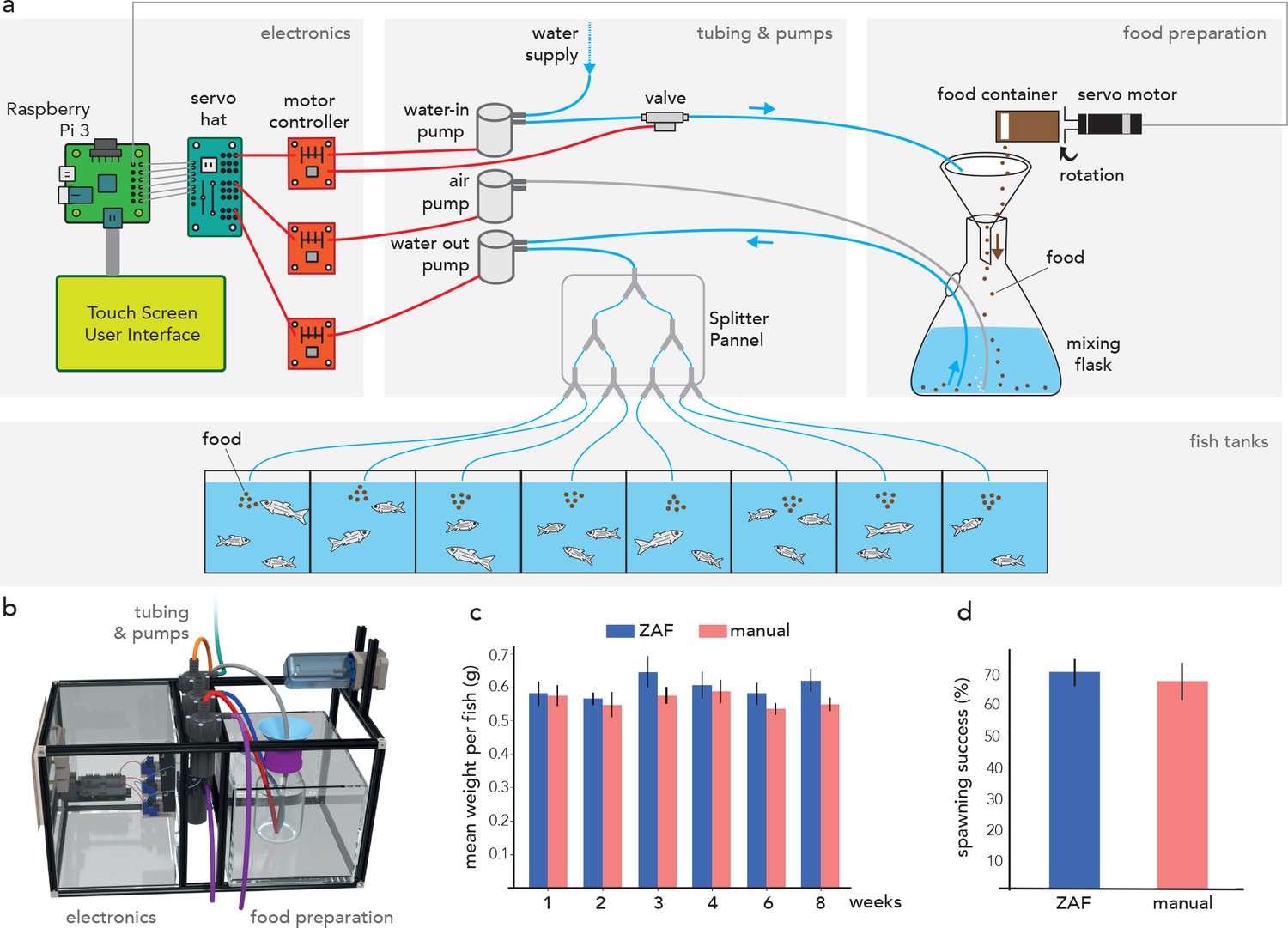
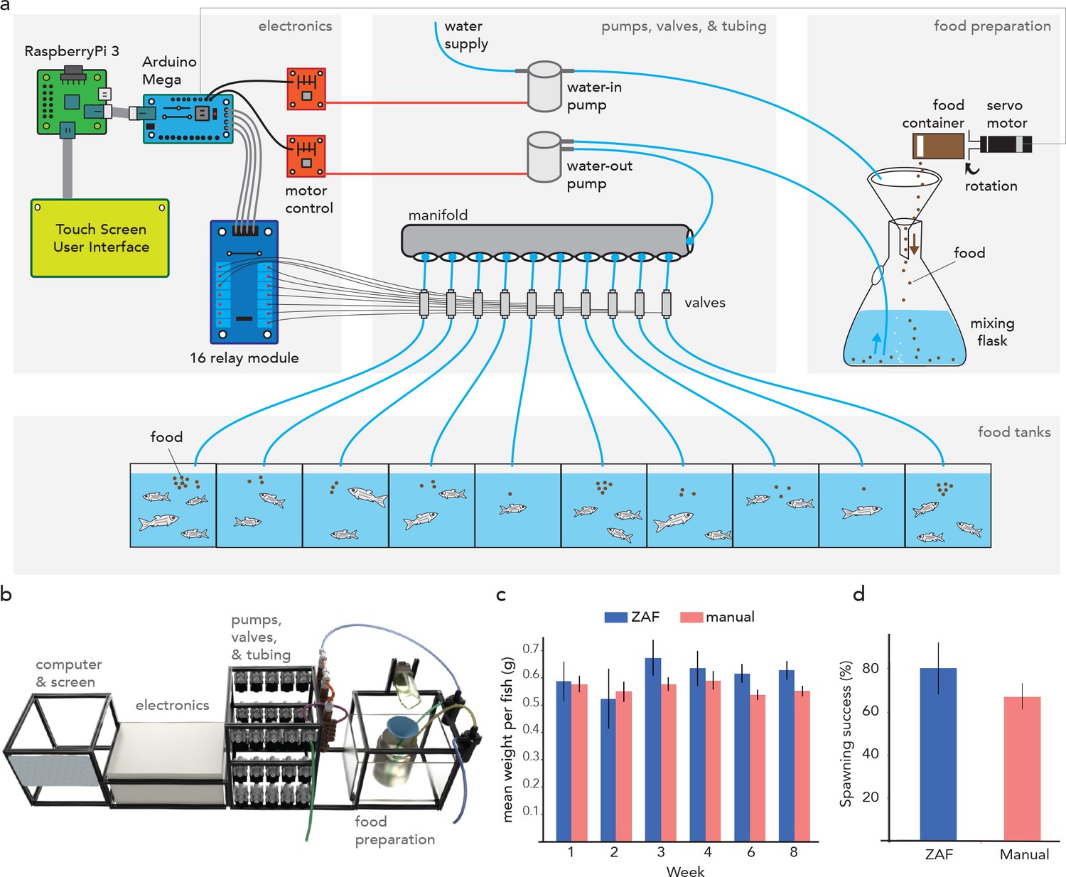
ZAF as a simple solution for aquatic facility feeding.
(a) Schematic representation of ZAF’s three main modules with their key components. Basic electronic wiring is also shown. ZAF is designed to distribute the same food quantity to all (fish) tanks. (b) 3D visualization of the different ZAF modules: electronics, tubing, pumps, and food preparation. (c) Variation of the fish mean weight over 8 weeks during ZAF feeding (n = 7) versus manually-fed fish (n = 6). (d) Spawning success for ZAF fed fish versus a manually-fed fish (spawning evaluated at weeks 2 and 6). All bars indicate s.e.m.
Figure 1—figure supplement 1
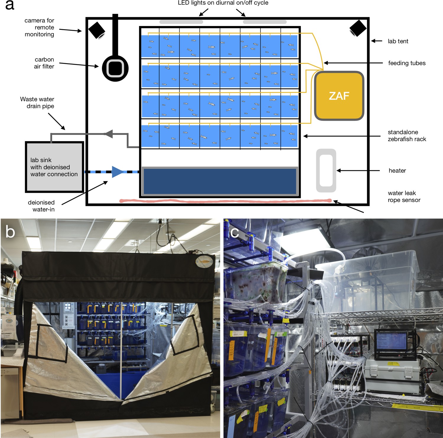
Automatising Zebrafish husbandry.
(a) Schematic representation of the standalone single rack zebrafish facility where we tested ZAFs. The facility is semi automatic and does not require constant human supervision. (b) Outside picture of the semi-automatic zebrafish facility. (c) ZAF+ inside the zebrafish facility.
Figure 1—figure supplement 2
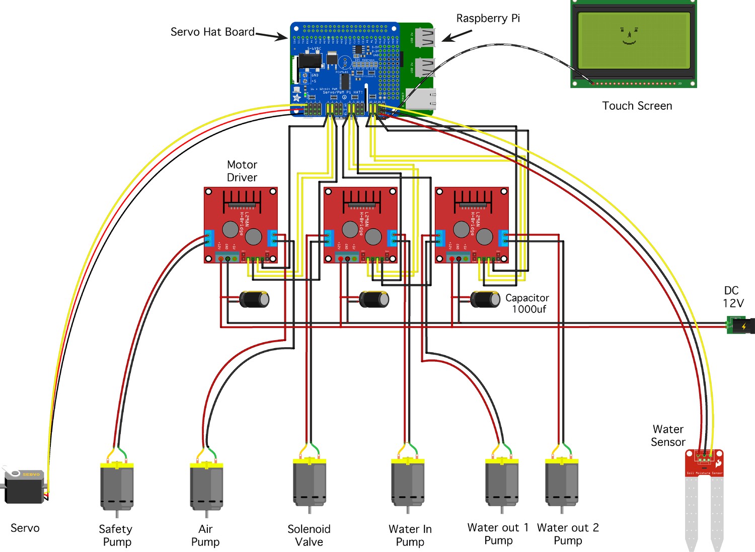
ZAF electronic diagram.
The design is based on a Raspberry computer, a Servo Hat Board to drive Pulse Width Modulation outputs and motor controller to control the pumps and valve. All the pumps and valves connected to the motor drivers are plugged on a 12V and 10A power supply converter. The Raspberry Pi, the servo hat and all the electronic connected to the servo hat are running with 5V through the Raspberry Pi power.
Figure 1—figure supplement 3
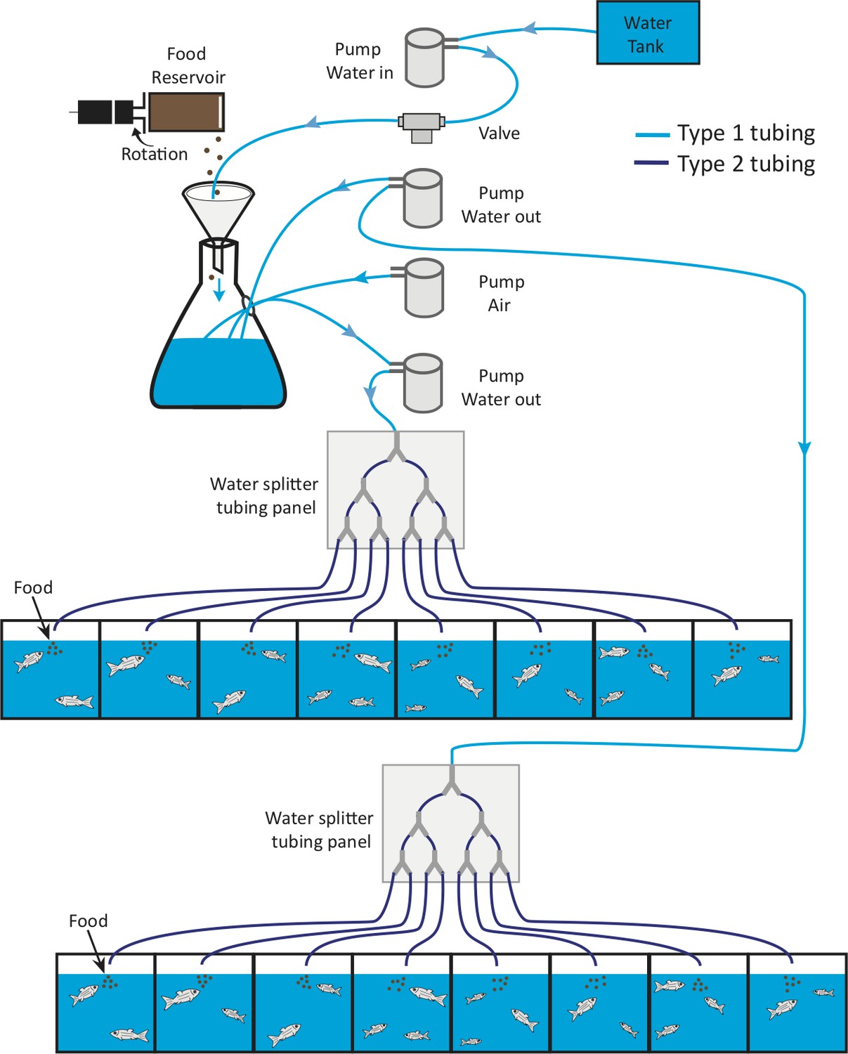
ZAF tubing.
In this schematic graph, we indicate how to connect the different pumps and valves together and where to the different types of tubing.
Figure 1—figure supplement 4
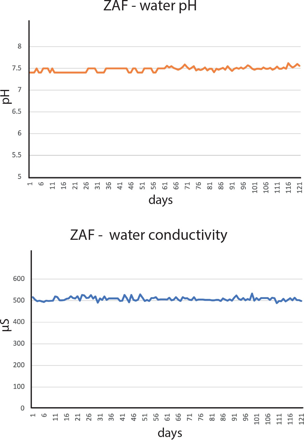
Water parameters log, pH and conductivity, during ZAF testing over a 3- month period.
Figure 2 with 4 supplements
ZAF+ is an advanced version of ZAF that can modulate food delivery per tank depending on fish density.
(a) Diagram of ZAF+. Electronics consist of: a Raspberry Pi 3, Arduino Mega, 16 relay module, an motor controllers. The water and food mix is pumped and sent via tubes to a manifold and valves that distribute it to specific tanks. (b) 3D representation of ZAF+ with extra space for the valves and a electronics box compared to the base ZAF version. (c) Evolution of the mean fish weight over 8 weeks of ZAF feeding (n = 6) versus the control group (n = 6). (d) Spawning success for fish fed by ZAF+ versus the control group. All bars indicate standard error mean.
Figure 2—figure supplement 1
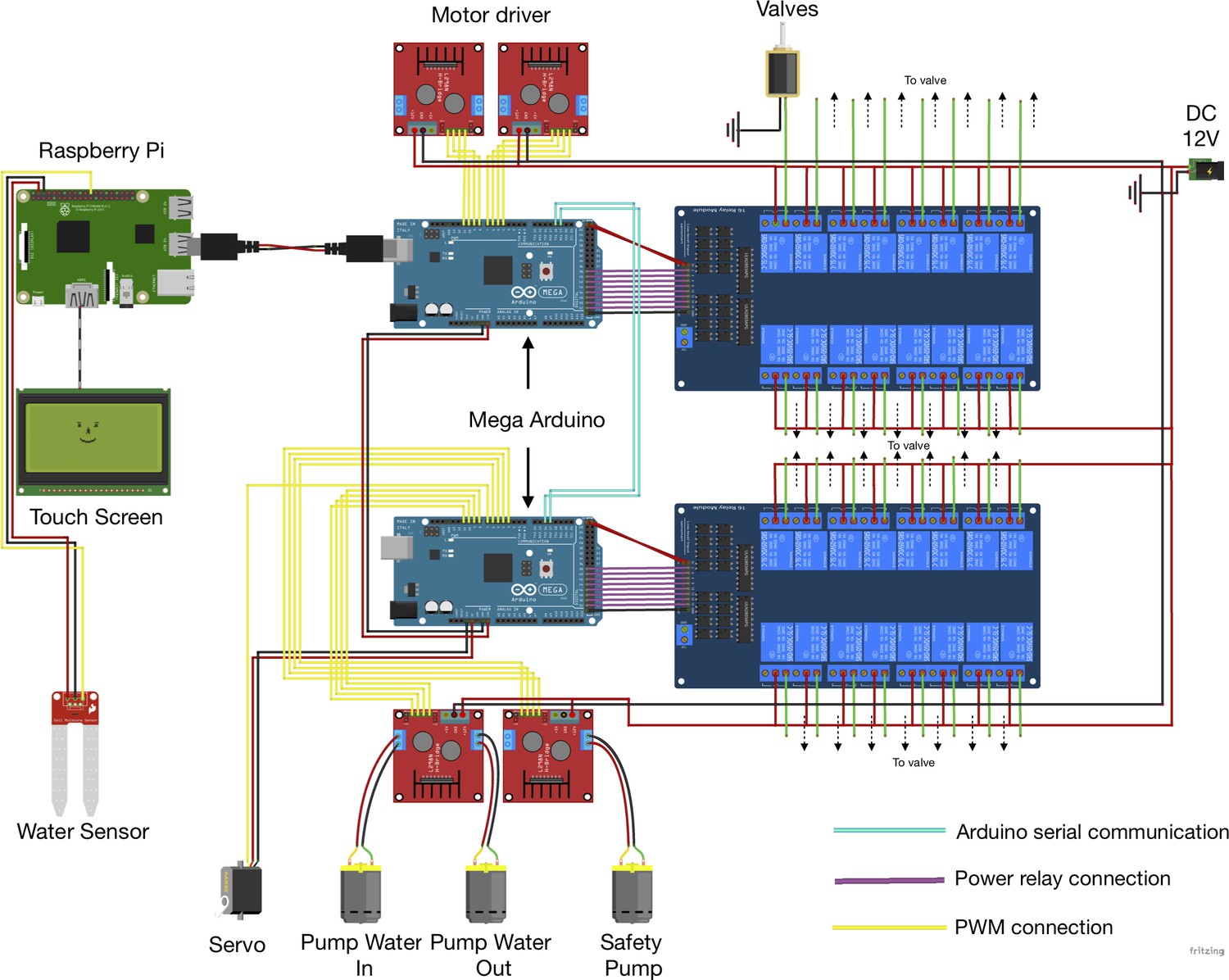
ZAF+ electronics diagram.
ZAF+ main electronics components are a Raspberry Pi 3B+ to run the software and control the electronics, Arduino Megas Arduino 2560 microcontrollers for the digital devices, motor controllers to control the various pumps and 16 Relay Module interface board to drive current and control the valves. The Raspberry Pi is connected directly to one Arduino Mega using a USB cable. The two Arduinos are daisy-chained via a serial connection (the whole design can be extended by daisy-chaining more arduinos). The Arduinos are connected to the motor controllers through digital pins. The Arduinos control the opening of each individual valve through the 16 relay module. A 12V power supply provides power to the electronics, except for the Raspberry Pi and the two Arduino Megas powered by the Raspberry Pi 5V.
Figure 2—figure supplement 2
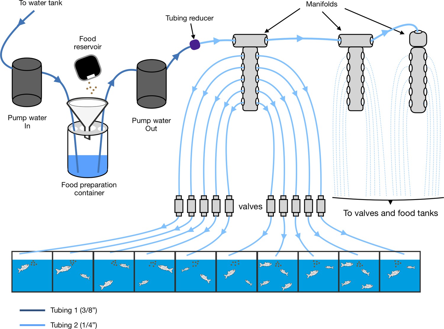
ZAF+ tubing.
The following schematic diagram represents the tubing connections between the different ZAF+ components. In order to connect the pump to multiple valves (30, in our case), we used manifolds that split the water flow into several tubes.
Figure 2—figure supplement 3
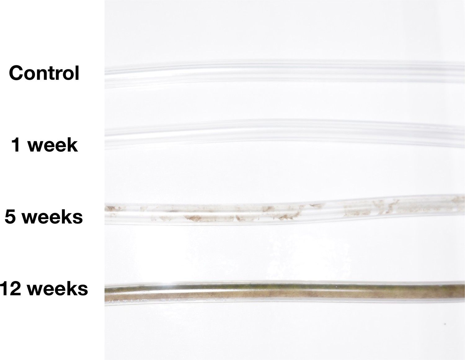
Tubing cleanliness evaluation.
In our fish facility conditions we observed that the tubes should be replaced every 12 weeks .
Figure 2—figure supplement 4
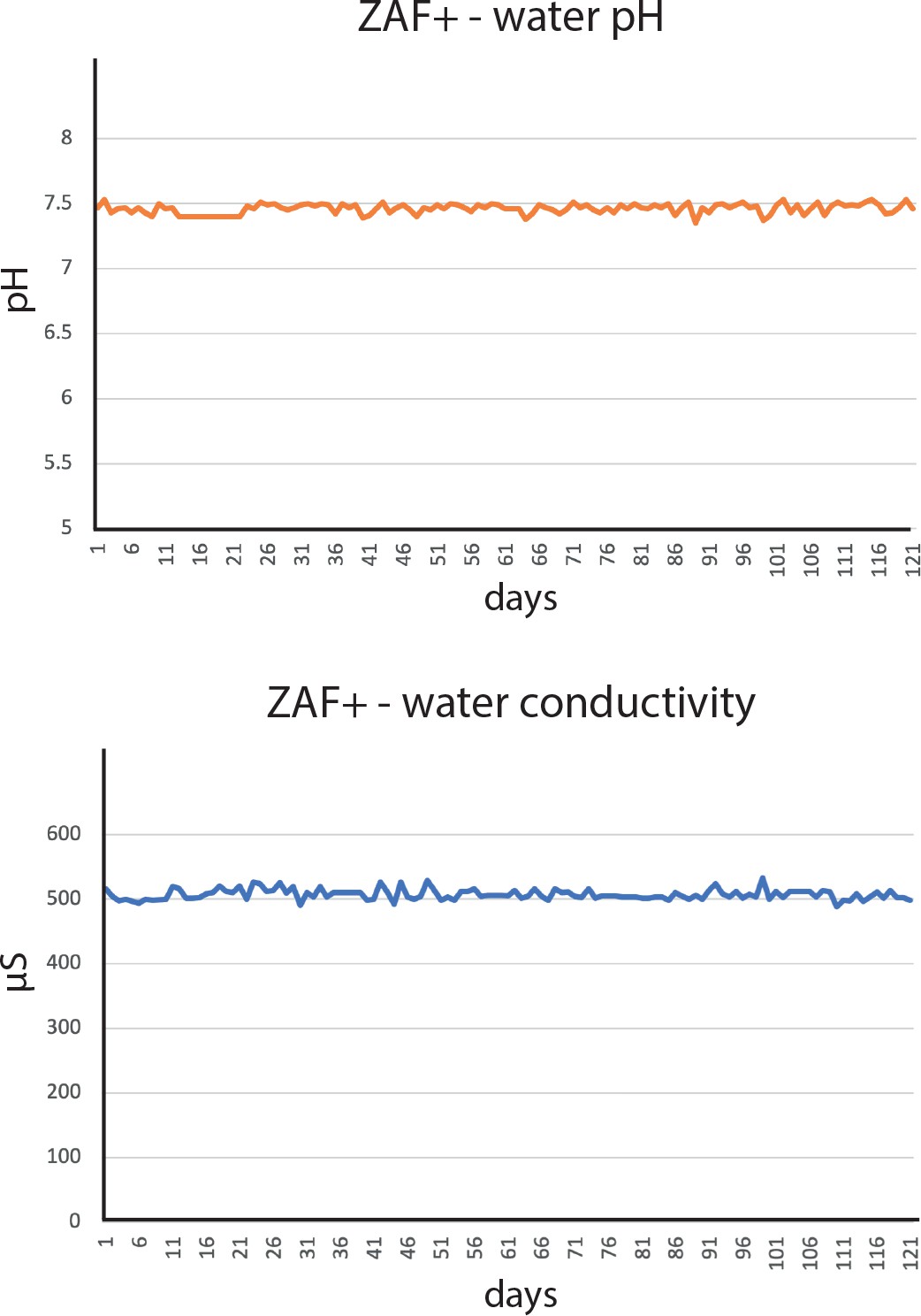
Water parameters log, pH and conductivity, during ZAF+ testing over a 3- month period.
Box 1—figure 1
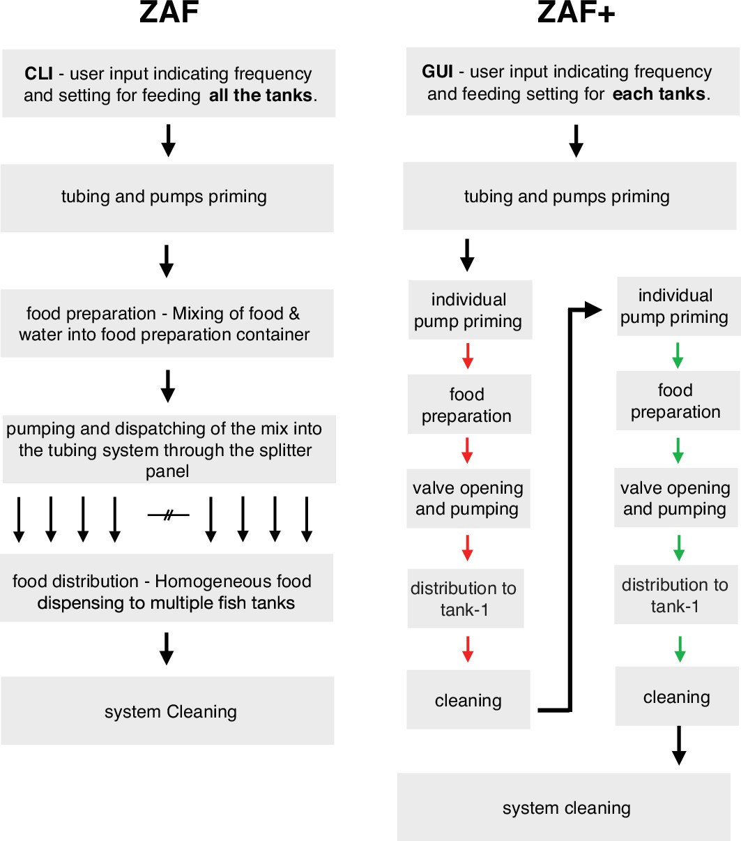
Diagram illustrating the differences during ZAF (left) and ZAF+ (right). ZAF is designed to distribute an homogeneous mix of food for all the tanks, whereas ZAF+ can control the amount of food per tanks.
Box 2—figure 1
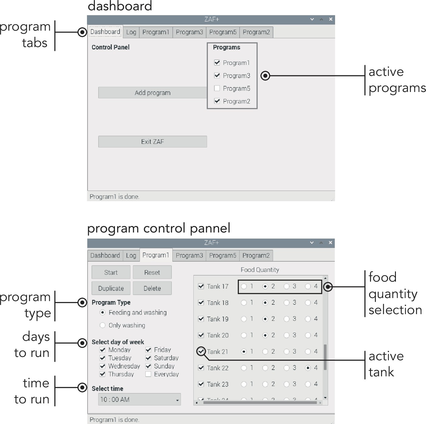
ZAF+ Graphic User Interface main panels. On the top panel ‘Dashboard’ displays the overview of the entire program. Bottom part illustrates the ‘Program tab’, where you set all the conditions for feeding and washing.
Videos
Video 1
ZAF presentation video, introducing the main features of the automatic feeders.
Additional files
-
Supplementary file 1
Detailed construction instruction for ZAF and ZAF+.
- https://cdn.elifesciences.org/articles/74234/elife-74234-supp1-v2.pdf
-
Supplementary file 2
ZAF+ parts list.
The table lists the necessary parts to build ZAF. Most of the parts are generic and can be replaced by components with similar specifications.
- https://cdn.elifesciences.org/articles/74234/elife-74234-supp2-v2.docx
-
Supplementary file 3
ZAF+ parts list.
The table lists the necessary parts to build ZAF+. Most of the parts are generic and can be replaced by components with similar specifications.
- https://cdn.elifesciences.org/articles/74234/elife-74234-supp3-v2.docx
-
Supplementary file 4
Troubleshooting guide.
This table provides solutions to common minor issues encountered during ZAFs construction and operations.
- https://cdn.elifesciences.org/articles/74234/elife-74234-supp4-v2.docx
-
Transparent reporting form
- https://cdn.elifesciences.org/articles/74234/elife-74234-transrepform1-v2.pdf
Download links
A two-part list of links to download the article, or parts of the article, in various formats.
Downloads (link to download the article as PDF)
Open citations (links to open the citations from this article in various online reference manager services)
Cite this article (links to download the citations from this article in formats compatible with various reference manager tools)
ZAF, the first open source fully automated feeder for aquatic facilities
eLife 10:e74234.
https://doi.org/10.7554/eLife.74234


