Differential ripple propagation along the hippocampal longitudinal axis
- Charité Universitätsmedizin Berlin, corporate member of Freie Universität Berlin, Humboldt-Universität zu Berlin, and Berlin Institute of Health; Neuroscience Research Center, Germany
- German Center for Neurodegenerative Diseases (DZNE) Berlin, Germany
- Charité-Universitätsmedizin Berlin, corporate member of Freie Universität Berlin, Humboldt-Universität Berlin, and Berlin Institute of Health, Einstein Center for Neuroscience, Germany
- Charité-Universitätsmedizin Berlin, corporate member of Freie Universität Berlin, Humboldt-Universität Berlin, and Berlin Institute of Health, NeuroCure Cluster of Excellence, Germany
- Humboldt-Universität zu Berlin, Bernstein Center for Computational Neuroscience, Germany
Figures
Figure 1 with 5 supplements
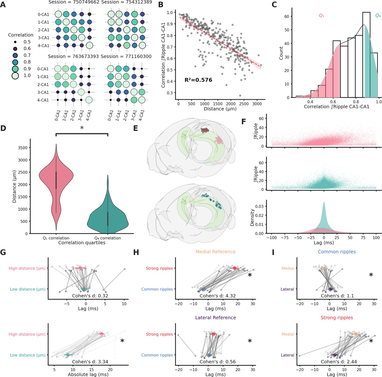
Ripple strength correlation depends significantly on distance.
(A) Correlation matrices showing the variabilty of ripple strength correlation between pairs of recording sites located in different CA1 locations in four example sessions. The number on the x- and y-axis labels indicates the probe number. Probes are numbered according to the position on the hippocampal longitudinal axis (0 is the most medial probe). (B) Scatter plot and linear regression showing the relationship between distance and correlation strength. Distance between recording sites explains 0.576% of the variability in correlation of ripple strength. (C) Ripple strength correlation distribution. Pink represents bottom 25% (<Q1) and blue top 25% (>Q4). (D) Violin plots showing that the top and bottom correlation quartiles show significantly different distance distributions (Q1: 2077.57 ± 68.68 µm, Q4: 633.56 ± 44.02 µm, p-value = 4.00e−23, Mann–Whitney U test). (E) Top: Rendering of the long-distance (top) and short-distance (bottom) CA1 pairs, dark circles are the reference locations in each pair. (F) Top and middle: scatter plots showing the relationship between ripple strength (at the reference location) and lag for long-distance (top, n ripples = 31,855) and short-distance (middle, n ripples = 52,858) pairs. Bottom: Kernel density estimate of the lags of long-distance (pink) and short-distance (turquoise) pairs. (G) Lag (top) and absolute lag (bottom) comparison between long- and short-distance pairs (top: long distance = −1.47 ± 0.63 ms, short distance = −0.51 ± 0.4 ms, p-value = 2.03e−01, Student’s t-test; bottom: long distance = 17.69 ± 0.38 ms, short distance = 8.69 ± 0.56 ms, p-value = 6.58e−20, Student’s t-test, asterisks mean p-value < 0.05). (H) Lag comparison in long-distance pairs between common and strong ripples with reference located inthe medial (top) or lateral hippocampal section (bottom) (top: strong ripples = 17.83 ± 1.02 ms, common ripples = −3.27 ± 0.68 ms, p-value = 2.28e−25, Student’s t-test, bottom: strong ripples = 3.62 ± 1.05 ms, common ripples = 0.88 ± 0.66 ms, p-value = 3.00e−02, Student’s t-test, asterisks mean p-value < 0.05). (I) Lag comparison in long-distance pairs between ripples with reference located in the medial and lateral sections in common (top) or strong ripples (bottom) (top: medial reference = −3.27 ± 0.68 ms, lateral reference = 0.88 ± 0.66 ms, p-value = 4.30e−05, Student’s t-test, bottom: strong ripples = 17.83 ± 1.02 ms, common ripples = 3.62 ± 1.05 ms, p-value = 4.30e−05, Student’s t-test, asterisks mean p-value < 0.05).
Figure 1—figure supplement 1
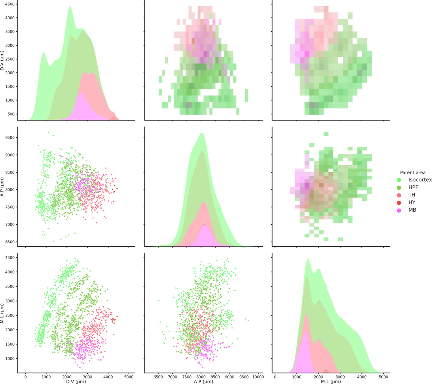
Spatial coordinates of all recorded brain regions.
2D histograms (upper diagonal), scatter plots (lower diagonal), and kernel density estimate plots (diagonal) of all the recorded regions color coded according to the Allen Institute color scheme. HPF = hippocampus, TH = thalamus, HY = hypothalamus, and MB = midbrain. Medio-lateral (M-L) axis is zeroed at the midline.
Figure 1—figure supplement 2
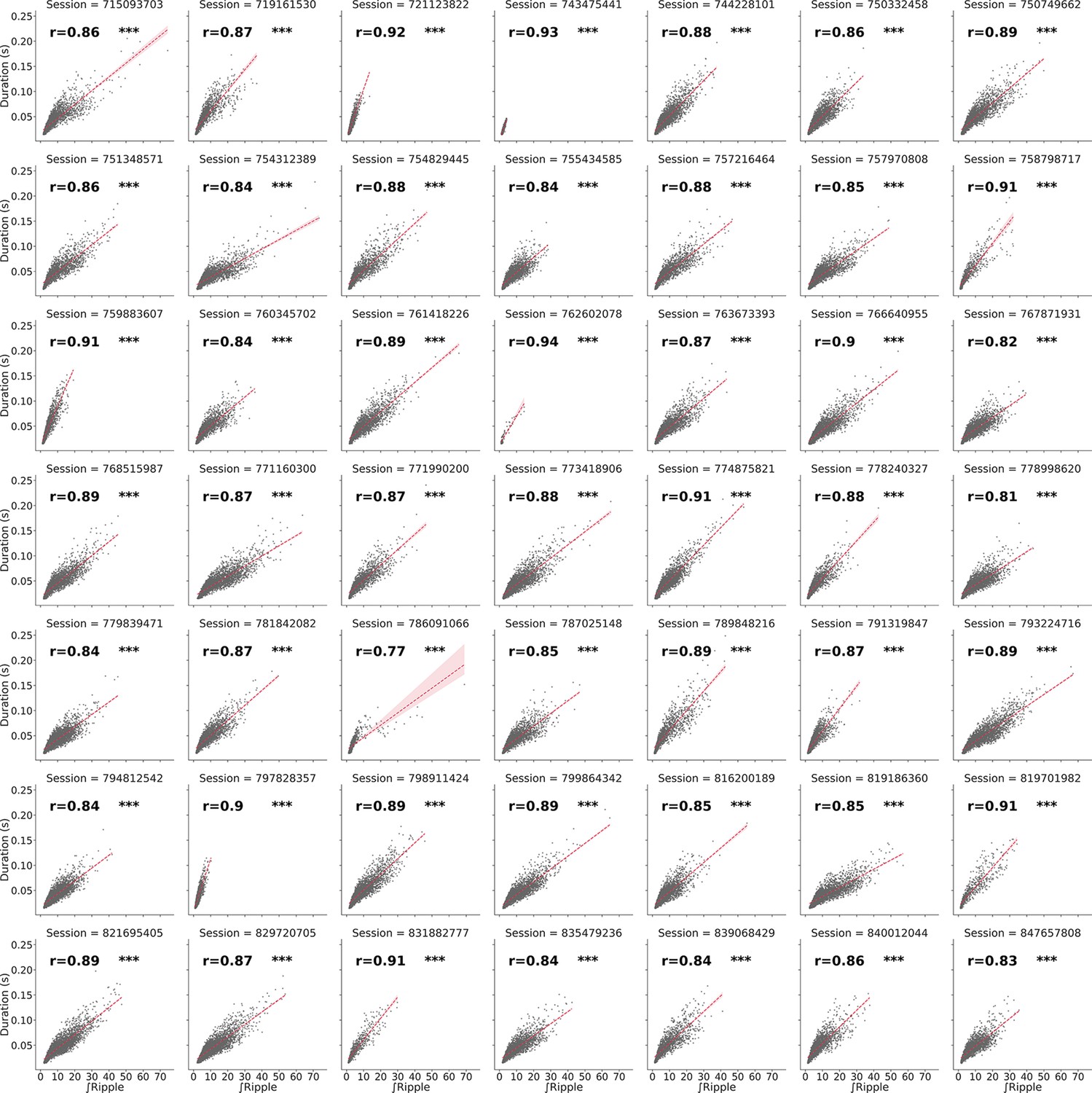
Correlation between ripple duration and strength per session.
Red line represents linear regression with confidence interval of 95% estimated via bootstrap. *** means p < 0.0005.
Figure 1—figure supplement 3
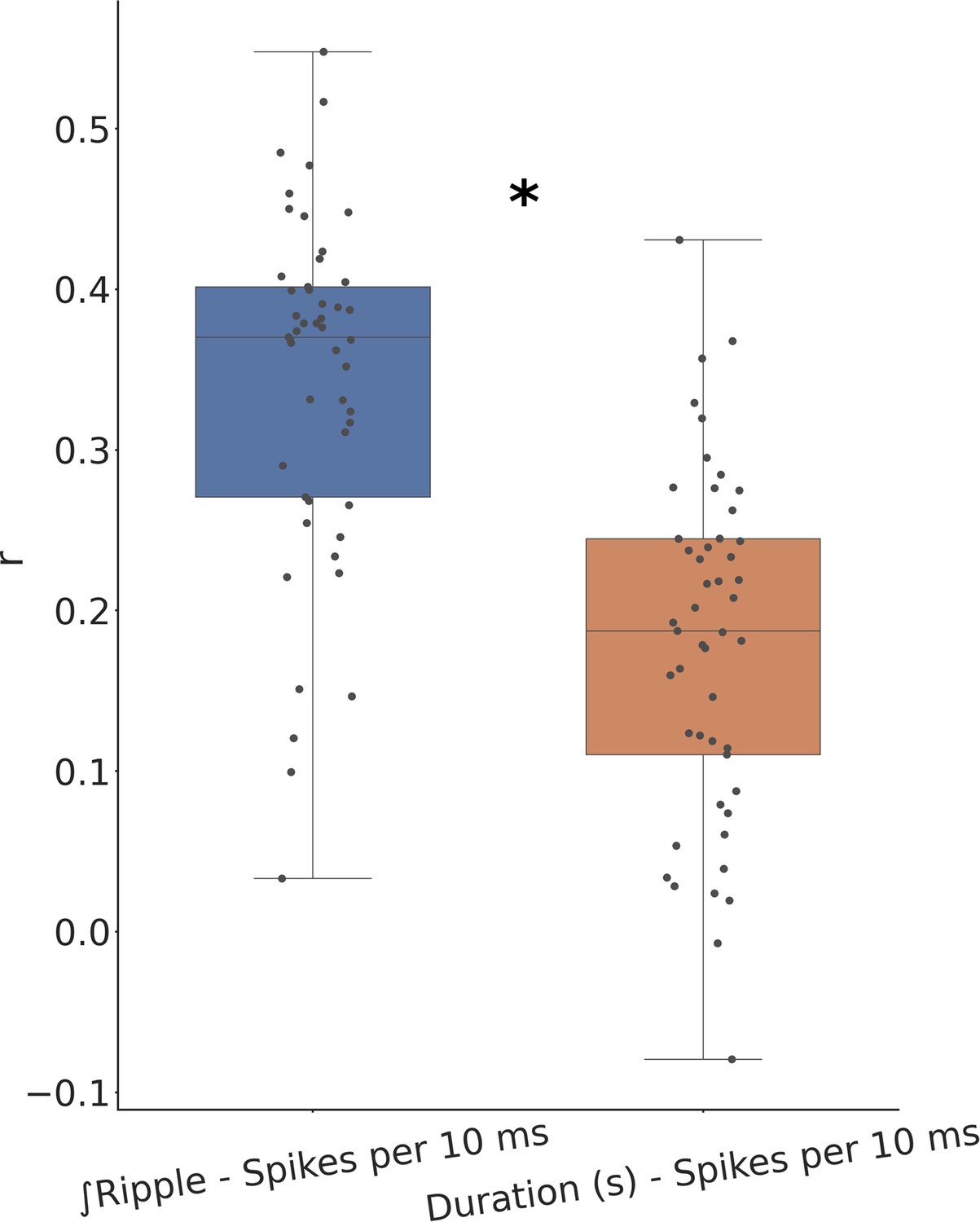
Comparison between correlation of ripple strength and duration with underlying spiking.
Ripple strength correlates significantly better with the underlying ripple spiking activity. * means p < 0.0005.
Figure 1—figure supplement 4
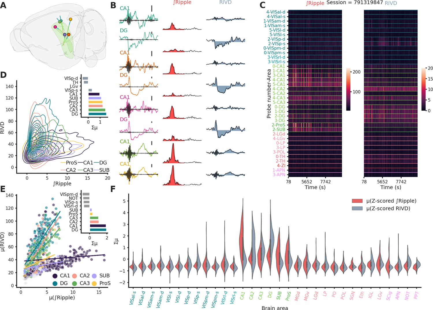
Ripple-associated local field potential (LFP) responses are predominantly observed in hippocampal structures.
(A) Rendering of probe locatiosn for session 791319847. (B) First column: Raw LFP traces color coded according to probe identity, superimposed in black the trace after high-pass filtering to show the presence of a ripple. Scale bar: 250 µV. Middle column: Ripple envelope and associated ∫Ripple in red. Last column: Raw LFP trace and associated ripple-induced voltage deflection (RIVD) in blue. (C) Heatmaps of ∫Ripple (left) and RIVD (right) for the entirety of session 791319847 and for each recorded area. To note the variability in ∫Ripple over time and cross different CA1 locations. (D) Kernel density estimate plot showing the relationship between ∫Ripple and RIVD. Bar plot shows the sum of the z-scored ∫Ripple and RIVD per area.for the areas showing the strongest responses in session 791319847. (E) Summary scatter plot showing the relationship between ∫Ripple and RIVD for all sessions. Bar plot shows the sum of the z-scored ∫Ripple and RIVD per area averaged across animals. Most of the activity is confined to the hippocampal formation (DG, CA1, CA2, CA3, SUB, and ProS) (n = 49). (F) Violin plots showing the distribution of ∫Ripple and RIVD z-scored per session, hippocampal regions (text in green) show the biggest responses.
Figure 1—figure supplement 5
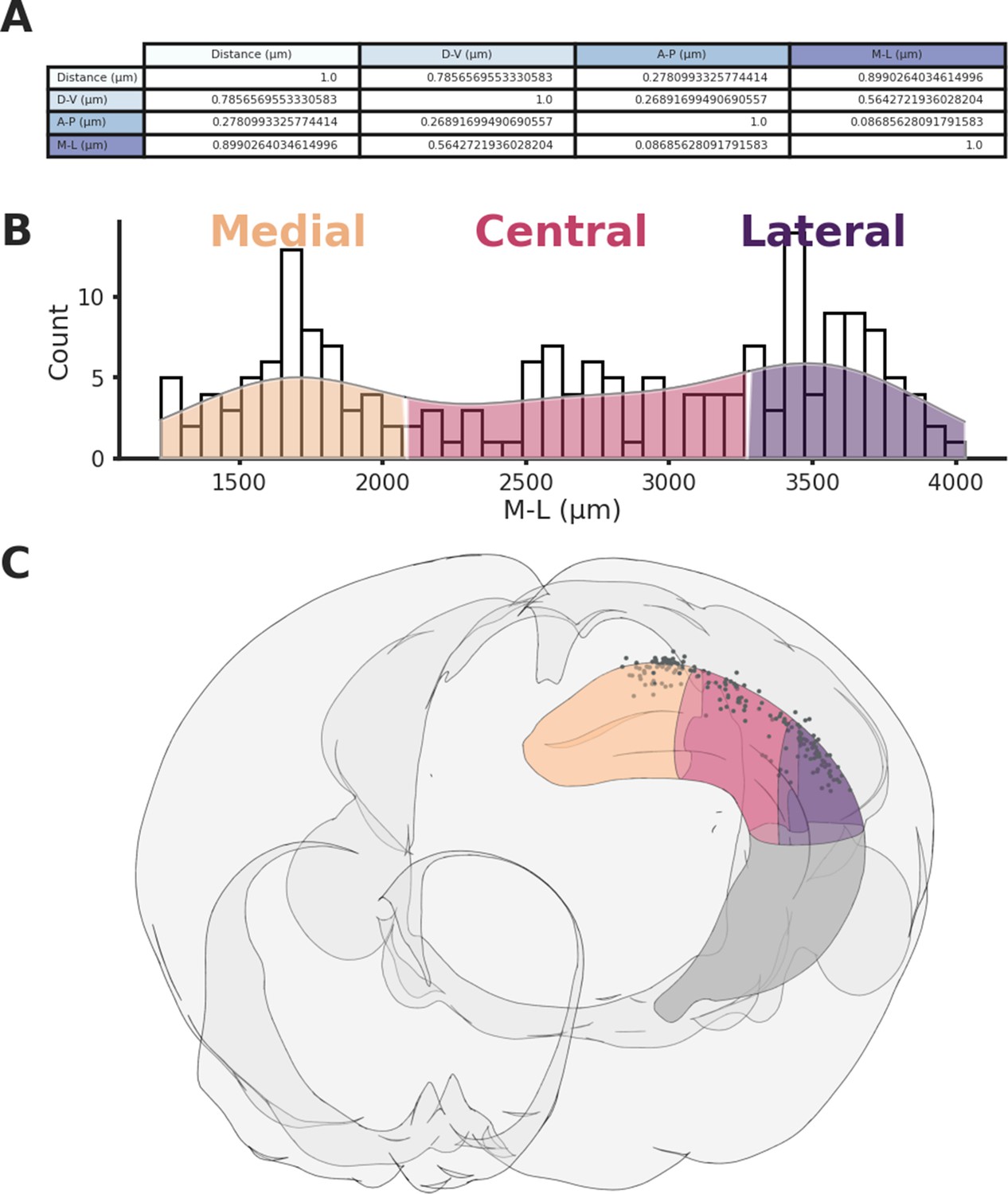
Hippocampal sections.
(A) Variance explained between 3D distances and distance on each spatial axis across CA1 recording locations. (B) Histogram showing the three sections across the medio-lateral (M-L) axis, the hippocampus was divided in order to have an equal number of recordings in each section. (C) Rendering of the three sections and associated recording locations (black dots).
Figure 2
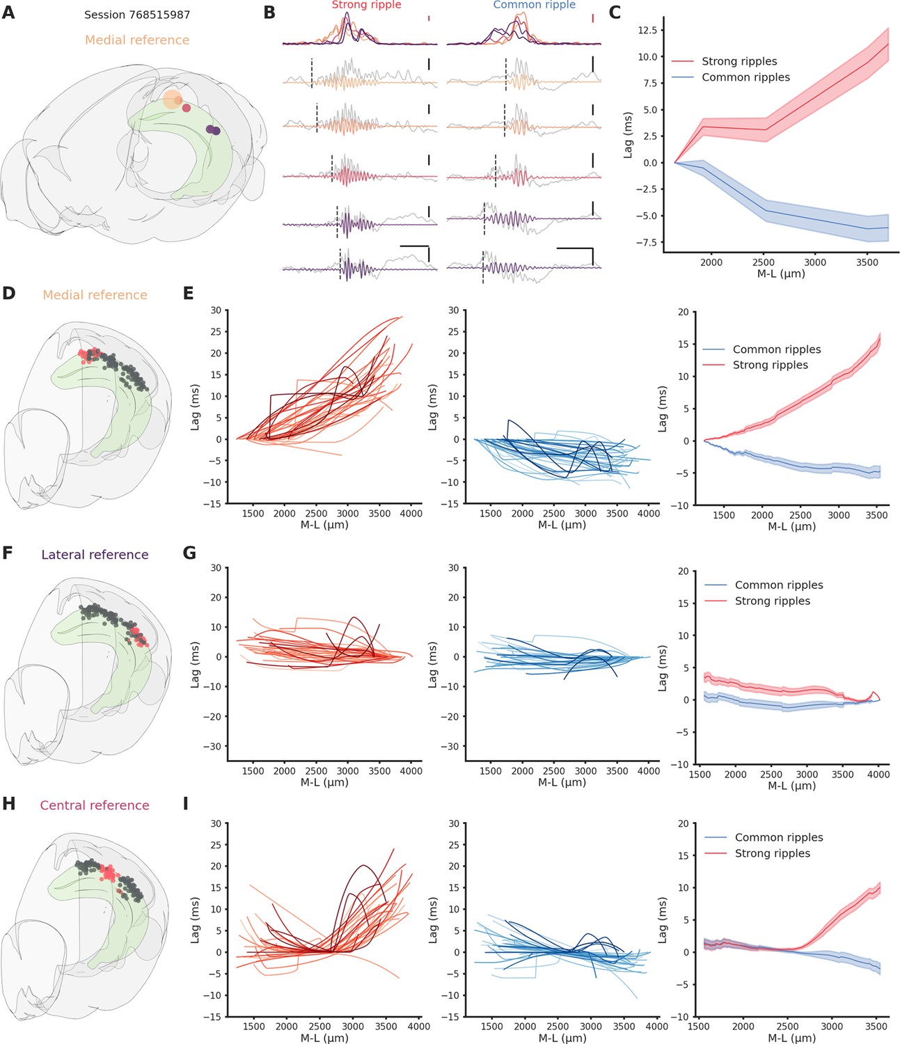
Direction-dependent differences in ripple propagation along the hippocampal longitudinal axis.
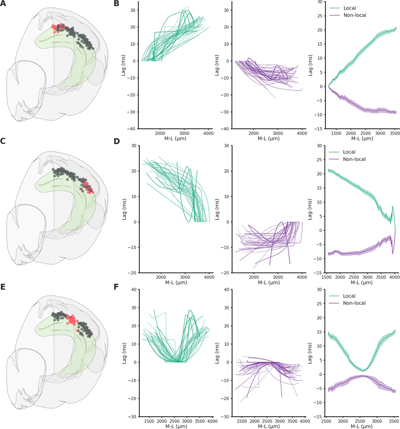
(A) Recording locations for session 768515987. Circles colors represent medio-lateral location. Bigger circle represents the reference location. (B) Example propagation of a strong (left column) and common (right column) ripple across the different recording location from session 768515987, each filtered ripple is color coded according to A. Gray traces represent raw local field potential (LFP) signal. Dashed vertical line represents the start of the ripple. In the top row the ripple envelope across all locations. Black scale bars: 50 ms, 0.5 mV. Red scale bars: 0.1 mV. (C) Average propagation map of strong and common ripples in session 768515987 across the medio-lateral axis. (D) Recording locations relative to E. Red circles represent the reference locations across all sessions (n sessions = 41), black circles represent the remaining recording locations. (E) Left: Medio-lateral propagation of strong ripples, each line represents the average of one session. Middle: Medio-lateral propagation of common ripples, each line represents the average of one session. Right: Average propagation map across sessions of strong and common ripples. Reference locations are the most lateral per session. (F) Same as D. (G) Same as E. Reference locations are the most lateral per session. (H) Same as D. (I) Same as E. Reference locations are the most central per session.
Figure 3 with 4 supplements
Ripples generation differences along the hippocampal longitudinal axis.
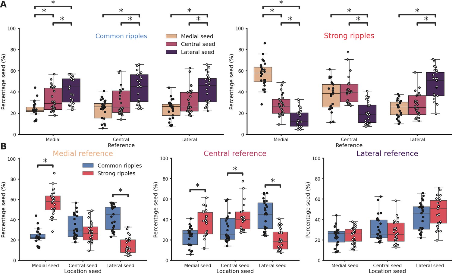
(A) Ripple seed location comparison between the three reference locations in common ripples (left) and strong ripples (right). Majority of common ripples seeds are located in the lateral hippocampal section regardless of the reference location (medial reference/lateral seed = 42.43 ± 2.45%, central reference/lateral seed = 43.77 ± 2.9%, lateral reference/lateral seed = 42.83 ± 2.75%). Strong ripples are mainly local (medial reference/medial seed = 56.78 ± 2.48%, central reference/central seed = 41.74 ± 2.58%, lateral reference/lateral seed = 46.76 ± 2.89%). (B) Ripple seed location comparison between strong and common ripples using a medial (left), central (center), or lateral reference (right). Asterisks mean p < 0.05, Kruskal–Wallis test with pairwise Mann–Whitney post hoc test.
Figure 3—figure supplement 1
Spatio-temporal lag maps of locally and not locally generated ripples.
Spatio-temporal profiles are symmetrical, strong indication of similar propagation speed regardless of seed position. (A) Recording locations relative to (B). Red circles represent the reference locations across all sessions (n sessions = 41), black circles represent the remaining recording locations. (B) Left: Medio-lateral propagation of locally generated ripples (generated in the reference section), each line represents the average of one session. Middle: Medio-lateral propagation of non-locally generated ripples, each line represents the average of one session. Right: Average propagation map across sessions of strong and common ripples. Reference locations are the most lateral per session. (C) Same as A. (D) Same as B. Reference locations are the most lateral per session. (E) Same as A. (F) Same as B. Reference locations are the most central per session.
Figure 3—figure supplement 2
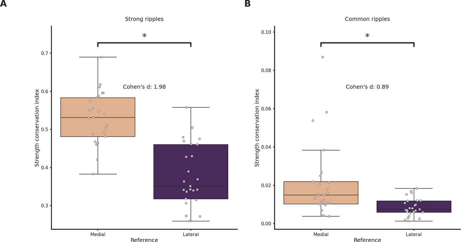
Strength conservation in medially and laterally generated ripples.
(A) Strength conservation index in strong ripples grouped by reference location. Ripples generated in the lateral section show significantly lower strength conservation (p-value = 7e−09, Student’s t-test, asterisks mean p-value < 0.05). (B) Strength conservation index in common ripples grouped by reference location (Student’s t-test, asterisks mean p-value < 0.05).
Figure 3—figure supplement 3
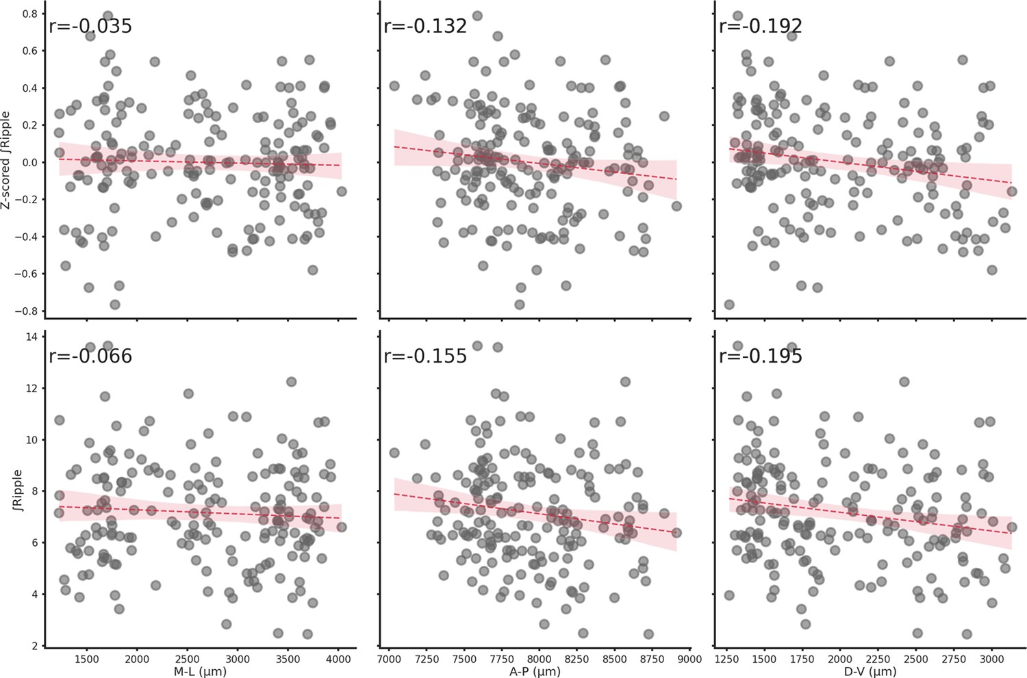
Spatial location does not influence ∫Ripple.
Relationship between z-scored ∫Ripple (top row) or ∫Ripple (bottom row) and each spatial axis (M-L, A-P, or D-V). Spatial location has a negligible effect on ∫Ripple.
Figure 3—figure supplement 4
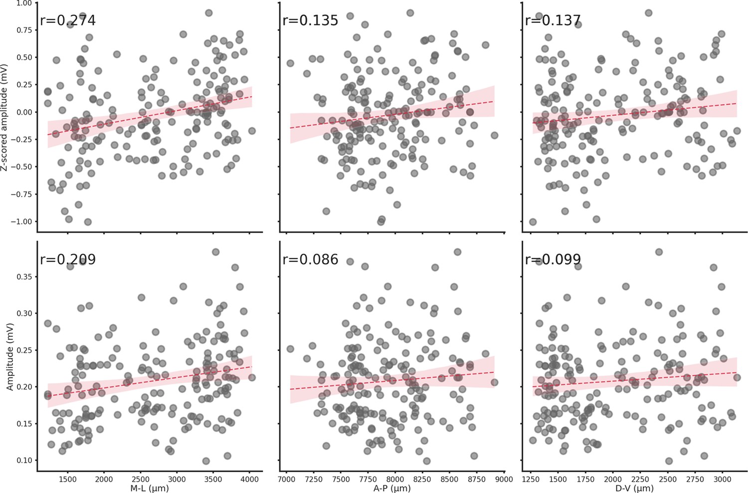
Spatial location does not influence ripple amplitude.
Relationship between z-scored amplitude (top row) or amplitude (bottom row) and each spatial axis (M-L, A-P, or D-V). Spatial location has a negligible effect on ripple amplitude.
Figure 4 with 4 supplements
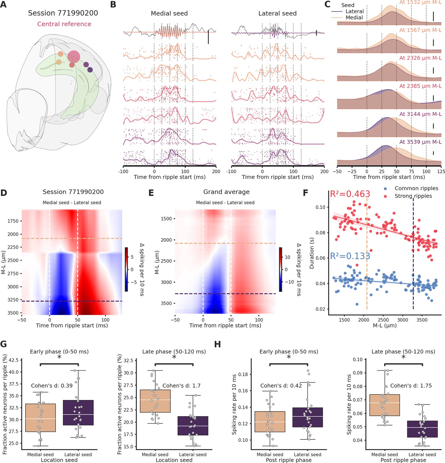
Ripples traveling in the medio→lateral direction show prolonged network engagement.
(A) Recording location for session 771990200. Circles colors indicate medio-lateral (M-L) location. Bigger circle represents the reference location. (B) Spiking activity across the hippocampal M-L axis associated with a ripple generated medially (left column) or lateraly (right column) across the different recording location from session 771990200. Spike raster plot and normalized density are plotted at each M-L location. In the top row filtered ripple, gray traces represent raw local field potential (LFP) signal. All plots are color coded according to A. Scale bar: 0.5 mV. (C) Kernel density estimates of the average spiking activity across different M-L locations and between seed type. Scale bar: 5 spikes per 10 ms. (D) Interpolated heatmap of the difference between medially and laterally generated ripple-induced spiking activity in session 771990200. Vertical dashed lines represent borders between early and late post-ripple start phases. Horizontal dashed lines represent the spatial limits of the hippocampal sections. (E) Grand average of the differences between medially and laterally initiated ripple-induced spiking activity across 24 sessions. Vertical dashed lines represent borders between early and late post-ripple start phases. Horizontal dashed lines represent the spatial limits of the hippocampal sections. (F) Regression plot between M-L location and ripple duration in common and strong ripples. Horizontal dashed lines represent the spatial limits of the hippocampal sections. (G) Average fraction of active neurons in medial (pink) and lateral (purple) ripples. Early/medial seed = 0.3 ± 0.69, early/lateral seed: 31.72 ± 0.84, p-value = 3.23e−05, Student’s t-test; late/medial seed = 24.57 ± 0.64, late/lateral seed = 19.44 ± 0.58, p-value = 4.09e−07, Student’s t-test. Asterisks mean p-value < 0.05. (H) Average spiking rate medial (pink) and lateral (purple) ripples. Early/medial seed = 0.12 ± 0.004, early/lateral seed = 0.13 ± 0.005, p-value = 1.35e−04, Student’s t-test; late/medial seed = 0.07 ± 0.002, late/lateral seed = 0.05 ± 0.002, p-value = 1.24e−12, Student’s t-test. Asterisks mean p-value < 0.05.
Figure 4—figure supplement 1

Differential spiking of hippocampal neurons between different conditions.
(A) Grand average of the differences between medial and lateral ripple-induced spiking activity in putative excitatory (left) and inhibitory neurons (right). Putative excitatory and inhibitory neurons show similiar spiking patterns in lateral and medial ripples. (B) Grand average of the differences between common and strong ripple-induced spiking activity in medial (left) and lateral ripples (right). Strong ripples are not associated with more spiking activity in the early phase post-ripple start (0–50 ms). (C) Grand average of the differences between medial and lateral ripple-induced spiking activity in common (left) and strong ripples (right). Strong ripples are associated with considerable differences between medial and lateral ripples.
Figure 4—figure supplement 2
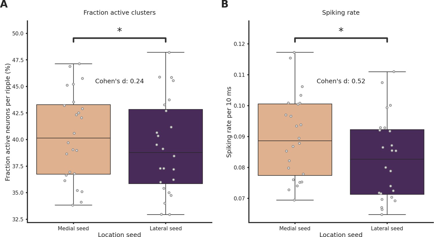
Spiking rate and fraction of active neurons are significantly higher in medial ripples.
(A) Fraction of active neurons per ripple grouped by ripple seed location (medial seed = 40.0 ± 1.0%, lateral seed = 39.0 ± 1.0%, p-value = 9.52e−05, Student’s t-test). (B) Average spiking rate grouped per ripple grouped by ripple seed location (medial seed = 9.0 ± 0.0%, lateral seed = 8.0 ± 0.0%, p-value = 5.20e−10, Student’s t-test). Asterisks mean p<0.05, Student’s t-test.
Figure 4—figure supplement 3
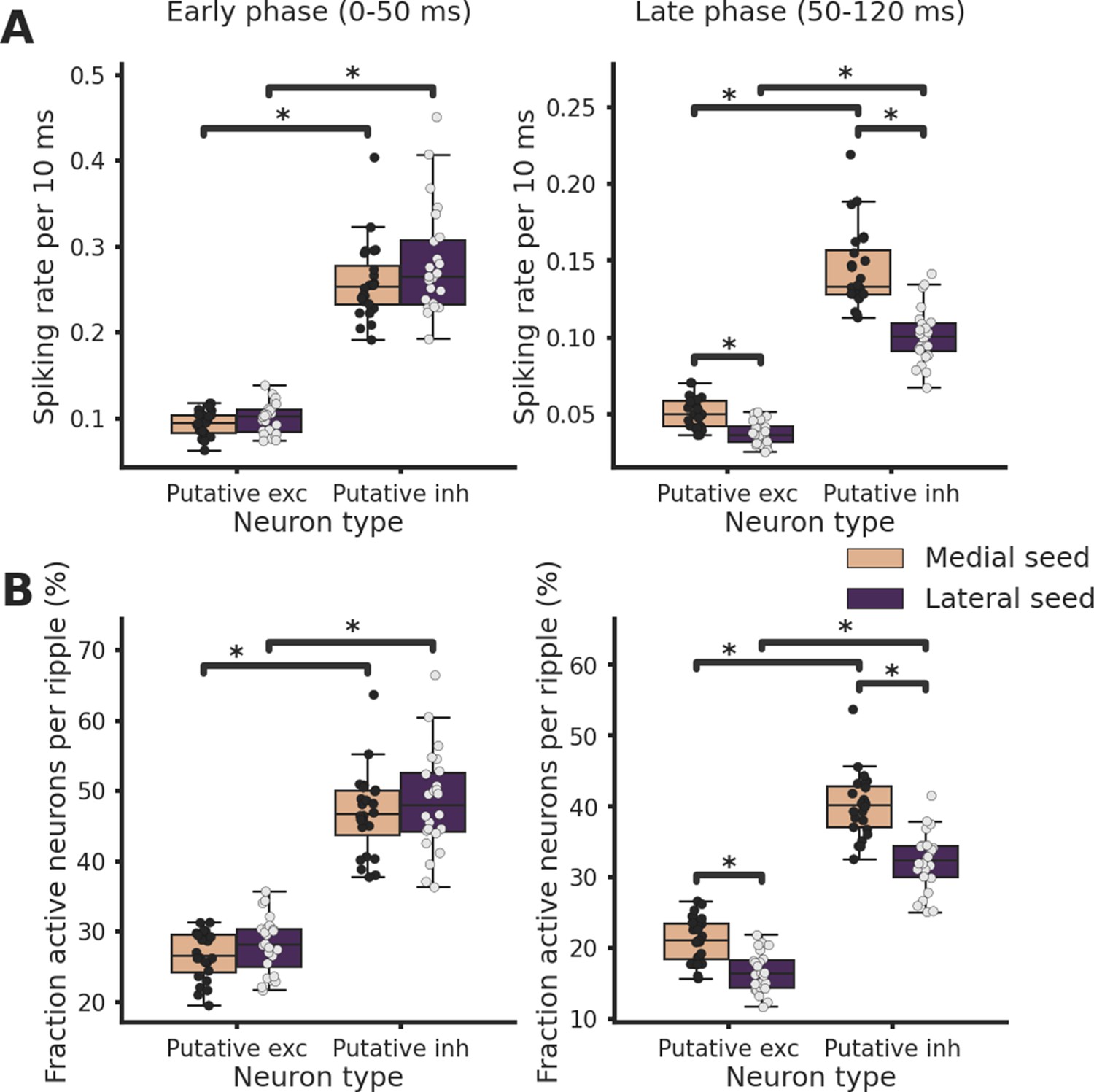
Spiking rate and fraction of active neurons are increased in the late phase post-ripple start in medial ripples both in putative excitatory and inhibitory neurons.
(A) Average spiking rate in early (left) and late (right) phase post-ripple start grouped by ripple seed location and putative neuron identity. Asterisks mean p < 0.05, analysis of variance (ANOVA) with pairwise Tukey post hoc test. (B) Fraction of active neurons per ripple in early (left) and late (right) phase post-ripple start grouped by ripple seed location and putative neuron identity. Asterisks mean p < 0.05, ANOVA with pairwise Tukey post hoc test.
Figure 4—figure supplement 4
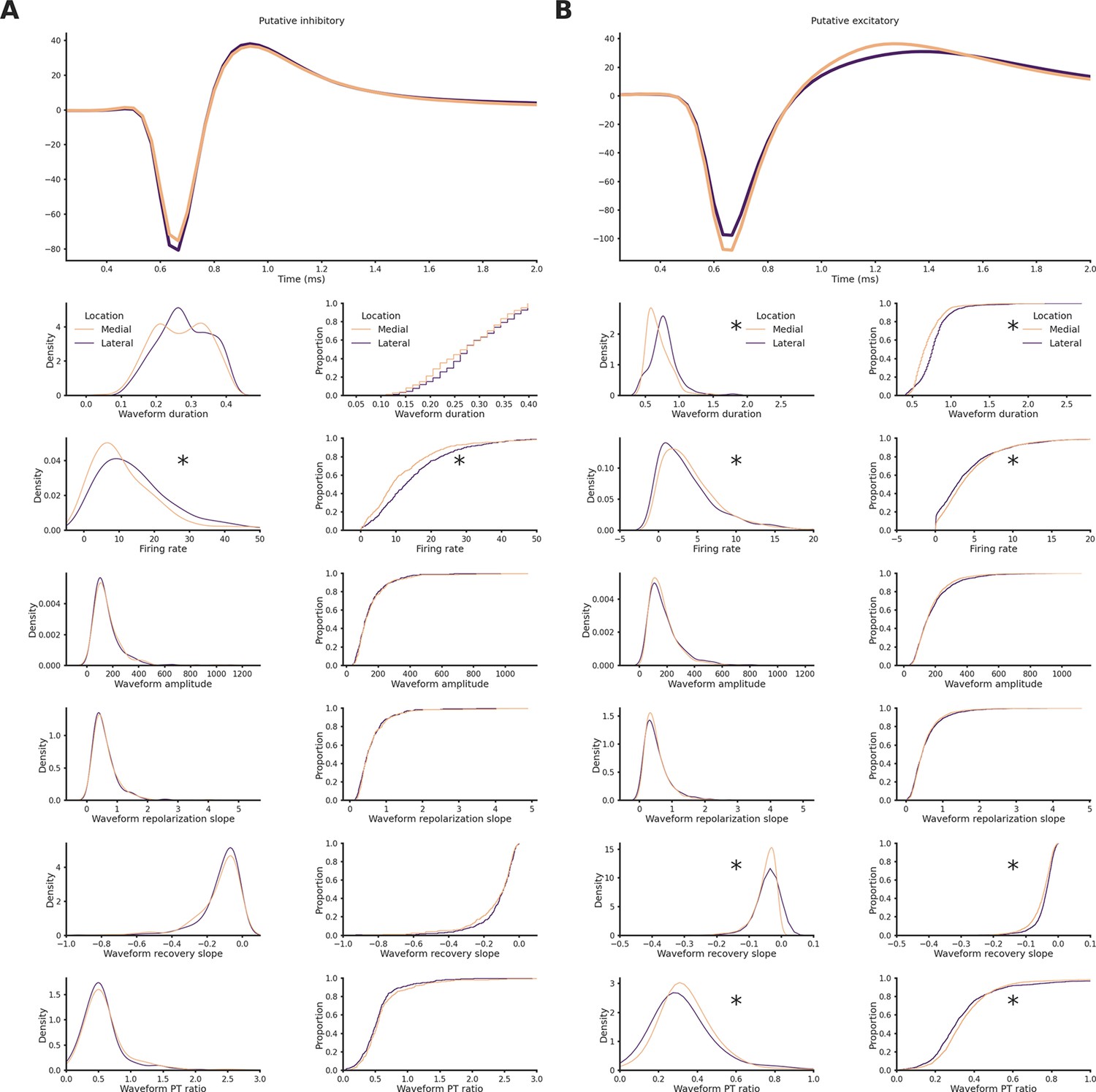
Units features in medial and lateral sections.
(A) Top: Average spike waveform of putative inhibitory neurons in medial or lateral sections. Bottom, left column: Kernel density estimate plot of waveform duration (p-value = 5.50e−05), firing rate (p-value = 6.17e−18), waveform amplitude (p-value = 1.69e−02), waveform repolarization slope (p-value = 6.71e−02), waveform recovery slope (p-value = 1.77e−02), and waveform peak-through ratio (p-value = 1.89e−01) grouped by hippocampal section. Asterisks mean p < 0.05, Mann–Whitney U test. Bottom, right column: Cumulative distribution plot of waveform duration (p-value = 4.37e−04), firing rate (p-value = 5.25e−14), waveform amplitude (p-value = 1.26e−01), waveform repolarization slope (p-value = 1.27e−01), waveform recovery slope (p-value = 1.73e−02), and waveform peak-through ratio (p-value = 1.66e−01) grouped by hippocampal section. Asterisks mean p-value < 0.05, Kolgomorov–Smirnov test. (B) Top: Average spike waveform of putative excitatory neurons in medial or lateral sections. Bottom, left column: Kernel density estimate plot of waveform duration (p-value = 8.18e−78), firing rate (p-value = 1.29e−09), waveform amplitude (p-value = 2.91e−02), waveform repolarization slope (p-value = 1.95e−01), waveform recovery slope (p-value = 1.51e−16), and waveform peak-through ratio (p-value = 1.18e−08) grouped by hippocampal section. Asterisks mean p < 0.05, Mann–Whitney U test. Bottom, right column: Cumulative distribution plot of waveform duration (p-value = 5.92e−100), firing rate (p-value = 1.74e−06), waveform amplitude (p-value = 1.61e−03), waveform repolarization slope (p-value = 1.44e−02), waveform recovery slope (p-value = 1.19e−14), and waveform peak-through ratio (p-value = 2.10e−08) grouped by hippocampal section. Asterisks mean p-value < 0.05, Kolgomorov–Smirnov test.
Figure 5 with 6 supplements

Ripple seed location influences the pattern of ripple modulation across various regions of the brain.
(A) Relationship between baseline (120 ms before ripple start) and ripple (0–120 ms) firing rate for clusters recorded in Isocortex, hippocampal formation (HPF), thalamus (TH), and midbrain (MB). Spiking rates were calculated as the mean between responses to lateral and medial ripples. Dashed black line represents absence of any influence, dashed red line represents a 50% increased spiking rate. (B) Ripple modulation of hippocampal clusters in response to lateral and medial ripples. Dashed black line represents absence of any influence, dashed red line represents a 50% increased spiking rate. CLES = commn-language effect size. Wilcoxon signed-rank test. Asterisk mean p-value < 0.05. (C) Top: Rendering of all clusters recorded in the hippocampal formation color coded by subfield. Middle: Kernel density plot showing distribution of clusters along the medio-lateral (M-L) axis. Dashed lines represent medial and lateral limits. Bottom: Stacked kernel density plot showing distribution of clusters along the M-L axis. (D) Ripple modulation in response to lateral and medial ripples during the early (left) and late (right) ripple phase. Errorbar represents the standard error of the mean. Wilcoxon signed-rank test or Student’s t-test (if normality established). Asterisks mean p-value < 0.05. (E) Ripple modulation in response to lateral and medial ripples before ripple start (20 ms). Errorbar represents the standard error of the mean. Wilcoxon signed-rank test or Student’s t-test (if normality established). Asterisks mean p-value < 0.05. (F) Left: Relationship between modulation by lateral and medial ripples in hippocampal clusters. Dashed black line represents absence of difference and twofold differences in both directions. Right: Pie chart representing hippocampal clusters preference in ripple engagement.
Figure 5—figure supplement 1
Spiking rate modulation in medial and lateral ripples across brain regions.
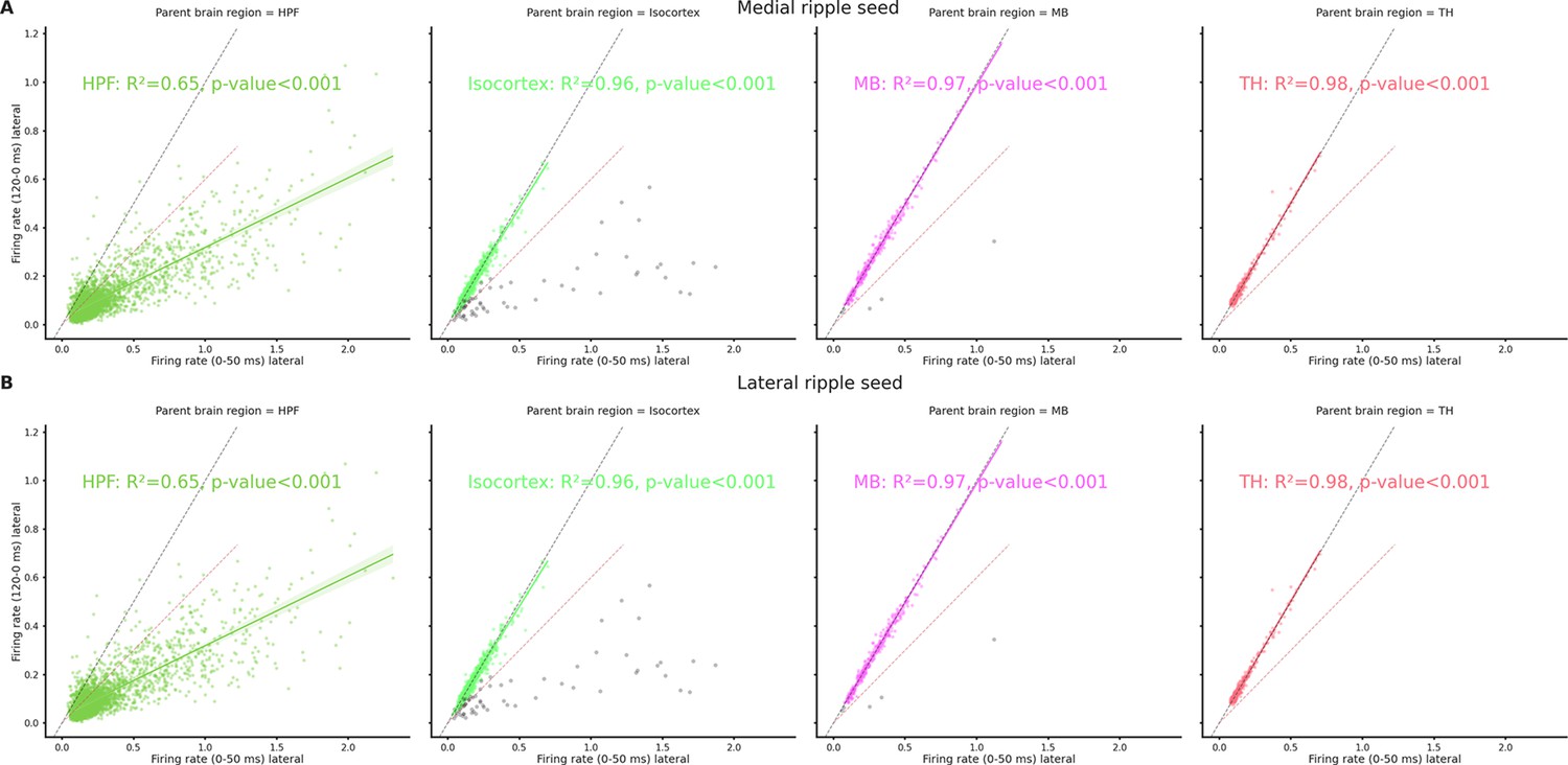
(A) Relationship between baseline (120 ms before ripple start) and medial ripple (0–50 ms) firing rate for clusters recorded in hippocampal formation (HPF), Isocortex, midbrain (MB), and thalamus (TH). In the Isocortex and MB plot, we excluded the minority of clusters showing modulation >50% in response to either lateral or medial ripples (gray dots). Dashed black line represents absence of any influence, dashed red line represents a 50% increased spiking rate. (B) Relationship between baseline (120 ms before ripple start) and lateral ripple (0–50 ms) firing rate for clusters recorded in HPF, Isocortex, MB, and TH. In the Isocortex and MB plot, we excluded the minority of clusters showing modulation >50% in response to either lateral or medial ripples (gray dots). Dashed black line represents absence of any influence, dashed red line represents a 50% increased spiking rate.
Figure 5—figure supplement 2
Ripple modulation density histograms.
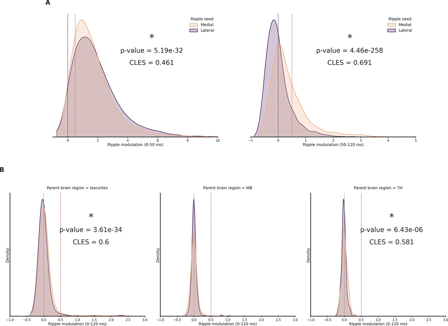
(A) Left: Early (0–50 ms) ripple modulation of hippocampal clusters in response to lateral and medial ripples. Dashed black line represents absence of any influence, dashed red line represents a 50% increased spiking rate. Wilcoxon signed-rank test. Right: Late (50–120 ms) ripple modulation of hippocampal clusters in response to lateral and medial ripples. Dashed black line represents absence of any influence, dashed red line represents a 50% increased spiking rate. Wilcoxon signed-rank test. Asterisks mean p-value < 0.05. (B) Ripple modulation of cortical (left), midbrain (MB; middle), and thalamus (TH; right) clusters in response to lateral and medial ripples. Dashed black line represents absence of any influence, dashed red line represents a 50% increased spiking rate. Wilcoxon signed-rank test. Asterisks mean p-value < 0.05.
Figure 5—figure supplement 3
Ripple modulation across hippocampal formation (HPF), Isocortex, midbrain (MB), and thalamus (TH).
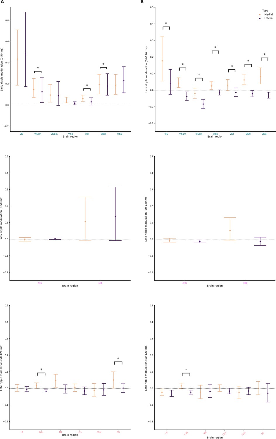
(A) Ripple modulation in response to lateral and medial ripples during the early ripple phase in cortical (top), MB (middle), and TH (bottom) clusters. Wilcoxon signed-rank test or Student’s t-test (if normality established). Asterisks mean p-value < 0.05. (B) Ripple modulation in response to lateral and medial ripples during the late ripple phase in cortical (top), MB (middle), and TH (bottom) clusters. Wilcoxon signed-rank test or Student’s t-test (if normality established). Asterisks mean p-value < 0.05.
Figure 5—figure supplement 4
Pre-ripple modulation across hippocampal formation (HPF), Isocortex, midbrain (MB), and thalamus (TH).
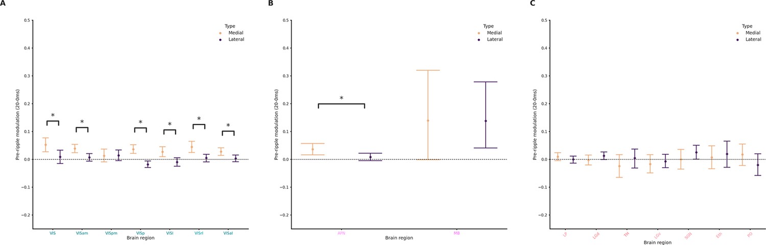
(A) Pre-ripple modulation in response to lateral and medial ripples during the early ripple phase in cortical clusters. Wilcoxon signed-rank test or Student’s t-test (if normality established). Asterisks mean p-value < 0.05. (B) Ripple modulation in response to lateral and medial ripples during the late ripple phase in MB clusters. Wilcoxon signed-rank test or Student’s t-test (if normality established). Asterisks mean p-value < 0.05. (C) Ripple modulation in response to lateral and medial ripples during the late ripple phase in TH clusters. Wilcoxon signed-rank test or Student’s t-test (if normality established).
Figure 5—figure supplement 5
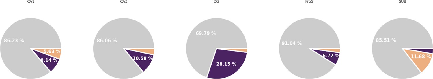
Clusters preference in ripple engagement by hippocampal subfields.
Preference in ripple engagement in CA1, CA3, DG, ProS, and SUB.
Figure 5—video 1
Cortical clusters showing ripple engagement.
In pink clusters showing medial ripples engagement (at least 25%), in purple clusters showing lateral ripples engagement (at least 25%), and in red clusters showing engagement (at least 25%) both in medial and lateral ripples.
Additional files
Download links
A two-part list of links to download the article, or parts of the article, in various formats.
Downloads (link to download the article as PDF)
Open citations (links to open the citations from this article in various online reference manager services)
Cite this article (links to download the citations from this article in formats compatible with various reference manager tools)
Differential ripple propagation along the hippocampal longitudinal axis
eLife 12:e85488.
https://doi.org/10.7554/eLife.85488


