Long-distance electron transport in multicellular freshwater cable bacteria
- Department of Physics and Astronomy, University of Southern California, United States
- Molecular and Computational Biology Section, Department of Biological Sciences, University of Southern California, United States
- Department of Chemistry, University of Southern California, United States
Figures
Figure 1
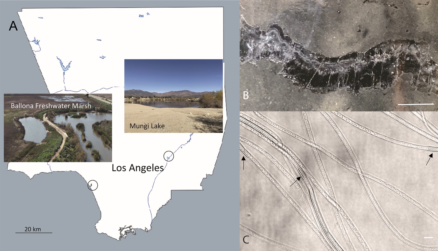
The sampling locations in Southern California and optical microscopy images of intact freshwater cable bacteria.
(A) Sampling sites for cable bacteria from the Ballona Freshwater Marsh and Mungi Lake, CA, USA. (B) Enrichment in laboratory incubations resulted in a high density of long cable bacteria filaments, some of which could be observed directly in cracked sediments. Scale bar: 35 mm. (C) Optical microscopy revealed the characteristic end-to-end multicellular morphology of the cable bacteria filaments, revealing occasional darker cells (black arrows) with slightly larger diameters, consistent with ‘empty cage’ cells scaffolded by the nanofiber network of cable bacteria (see Figure 2). Scale bar: 5 µm.
Figure 2
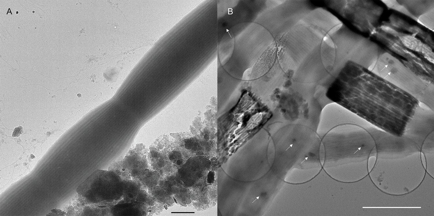
Transmission electron microscopy images of freshwater cable bacteria.
(A) Transmission electron microscopy of Ballona Freshwater Marsh cable bacteria showing the characteristic cell surface ridge pattern. Scale bar: 1 µm. (B) The underlying network of parallel periplasmic nanofibers can be seen clearly in occasional degraded cells as the electron-dense scaffold of “empty cages”. Small intracellular dark globules (white arrows) are consistent with polyphosphate granules commonly found in marine cable filaments. Scale bar: 2.5 µm.
Figure 3

Phylogenetic tree based on 16S rRNA gene sequences of the Ballona Freshwater Marsh and Mungi Lake cable bacteria, other cable bacterial Candidatus taxa, and representatives of isolated members from the family Desulfobulbaceae.
Scale bar represents 10% estimated sequence divergence. Bootstrap numbers (1000 re-samplings) > 70 are listed.
Figure 4
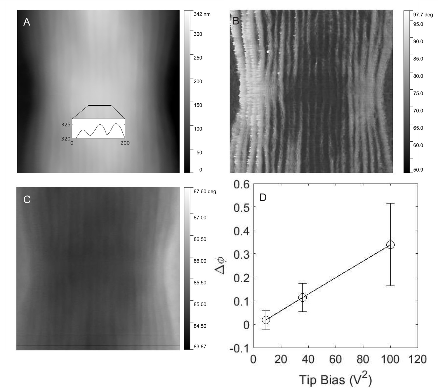
Electrostatic force microscopy on cable bacteria.
(A) Tapping mode atomic force microscopy of freshwater cable bacteria near the junction between two cells. Inset is a cross-sectional line scan showing cell surface ridge pattern. (B) Atomic force phase image corresponding to the topographical scan and showing the ridge pattern in high contrast. (C) Electrostatic force microscopy image with a 6 V tip bias, collected from the retrace scan at 50 nm fixed height above the cable surface. The contrast in this image stems from the electric force rather than topography. (D) The voltage dependence of the electrostatic interaction (phase shift, Δφ, of the ridges with higher electric force relative to inter-ridge regions) between the conductive tip and the same cable bacterial filament from (C).
-
Figure 4—source data 1
Measured AFM height data with 10 V tip bias and 30 nm tip height.
- https://cdn.elifesciences.org/articles/91097/elife-91097-fig4-data1-v1.zip
-
Figure 4—source data 2
Measured AFM napphase data with 10 V tip bias and 50 nm tip height.
- https://cdn.elifesciences.org/articles/91097/elife-91097-fig4-data2-v1.zip
-
Figure 4—source data 3
Measured AFM phase data with 10 V tip bias and 50 nm tip height.
- https://cdn.elifesciences.org/articles/91097/elife-91097-fig4-data3-v1.zip
-
Figure 4—source data 4
Measured AFM height data with 3 V tip bias and 50 nm tip height.
- https://cdn.elifesciences.org/articles/91097/elife-91097-fig4-data4-v1.zip
-
Figure 4—source data 5
Measured AFM napphase data with 3 V tip bias and 50 nm tip height.
- https://cdn.elifesciences.org/articles/91097/elife-91097-fig4-data5-v1.zip
-
Figure 4—source data 6
Measured AFM phase data with 3 V tip bias and 50 nm tip height.
- https://cdn.elifesciences.org/articles/91097/elife-91097-fig4-data6-v1.zip
-
Figure 4—source data 7
Measured AFM height data with 6 V tip bias and 50 nm tip height.
- https://cdn.elifesciences.org/articles/91097/elife-91097-fig4-data7-v1.zip
-
Figure 4—source data 8
Measured AFM napphase data with 6 V tip bias and 50 nm tip height.
- https://cdn.elifesciences.org/articles/91097/elife-91097-fig4-data8-v1.zip
-
Figure 4—source data 9
Measured AFM phase data with 6 V tip bias and 50 nm tip height.
- https://cdn.elifesciences.org/articles/91097/elife-91097-fig4-data9-v1.zip
Figure 5 with 1 supplement
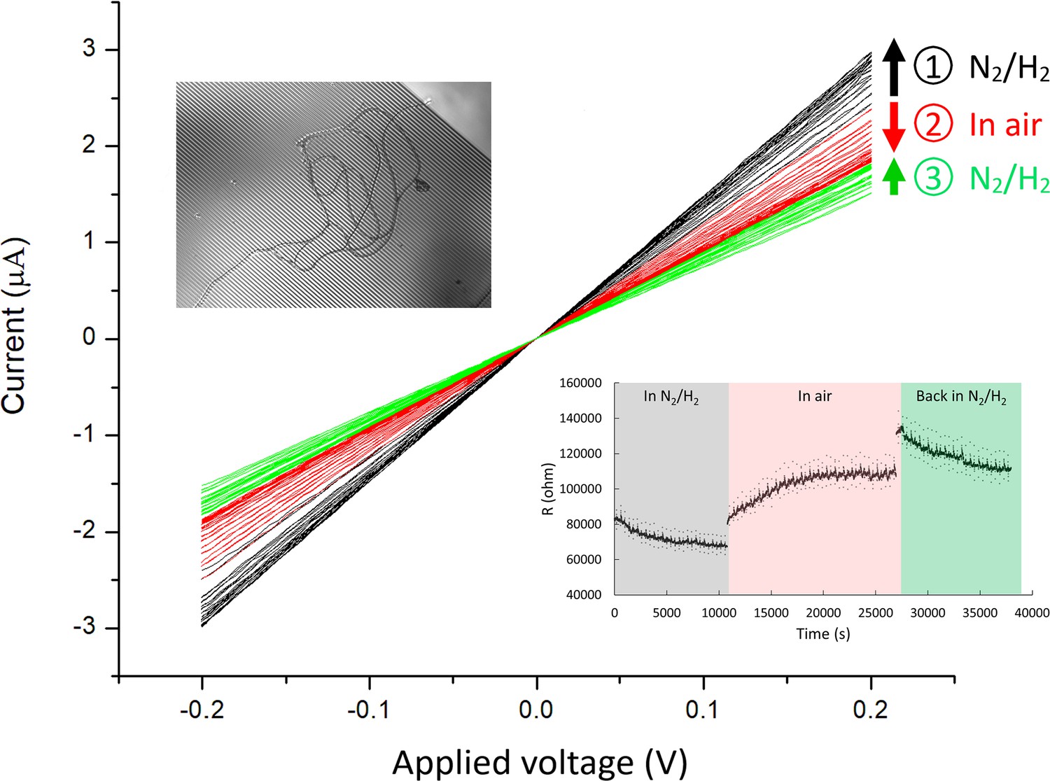
Current-voltage (I–V) measurements of Ballona Freshwater Marsh cable bacteria on gold interdigitated array (IDA) microelectrodes (3 µm gap between the fingers of the two electrode bands).
For this measurement, two cable filaments were deposited on the IDA (inset). The I–V measurements (black) show a modest increase in conductance over time (3 hr) during consecutive measurements in an air-free environment (95% N2 and 5% H2). Upon air exposure (red), the conductance slowly declined over time (2.7 hr), and conductance recovered partially after re-insertion into an air-free environment (green). Arrow direction denotes measurements over time for a particular condition. The lower right inset demonstrates the resistivity change over time at different conditions.
-
Figure 5—source data 1
An example of sensitivity of conduction in cable bacteria to air exposure.
- https://cdn.elifesciences.org/articles/91097/elife-91097-fig5-data1-v1.xlsx
Figure 5—figure supplement 1

An example of sensitivity of conduction in cable bacteria to air exposure.
Consistent current is monitored overnight for a Ballona freshwater sediment cable bacteria filament on an interdigitated array (IDA) under N2 flow conditions, with an 800 mV difference between the two microelectrode bands. The current immediately declined upon interruption of N2 flow and exposure to air.
Figure 6
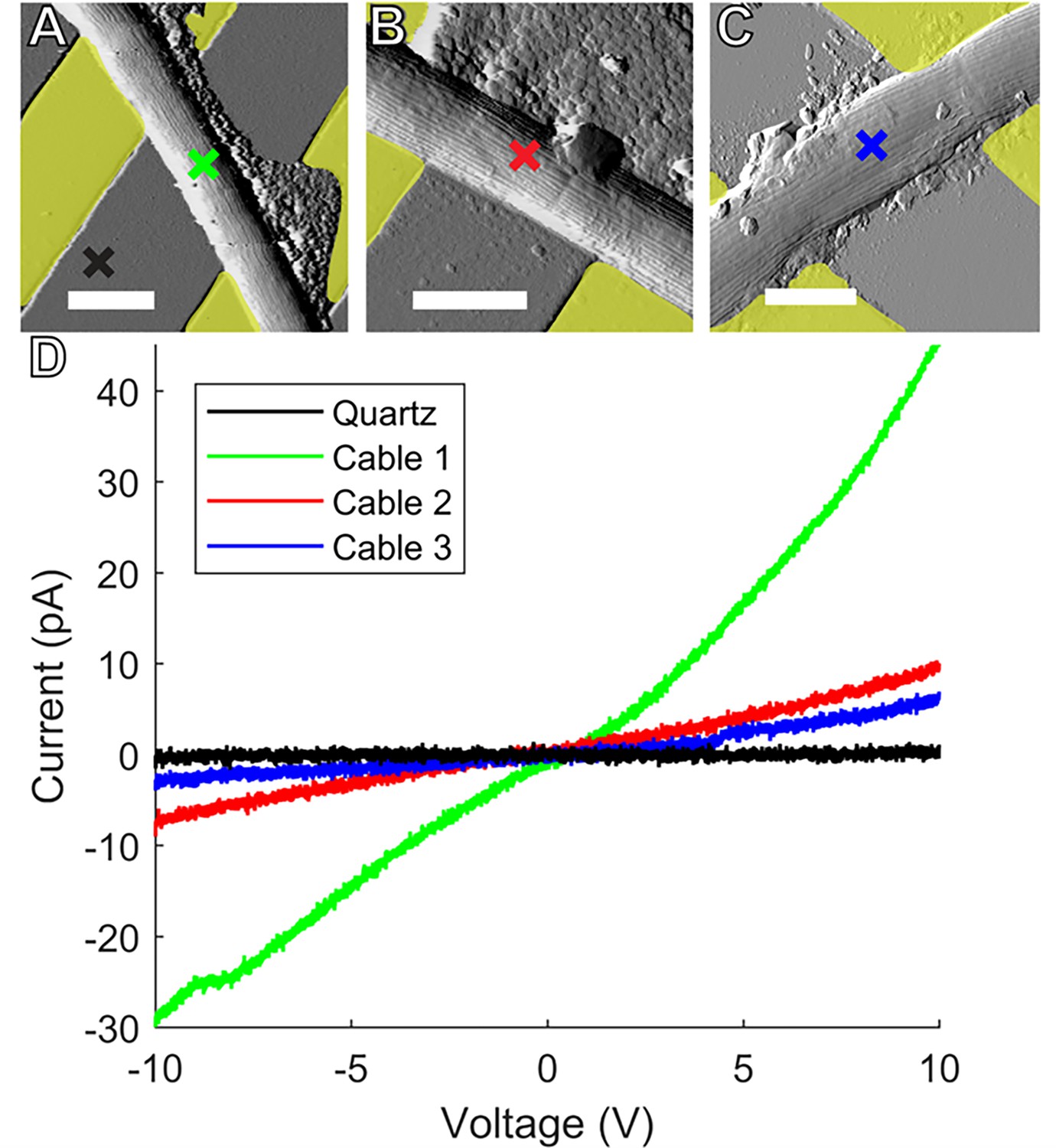
Conductive AFM point I-V measurements.
Representative atomic force microscopy amplitude images of Ballona freshwater cable bacteria filaments spanning the insulating quartz gap between yellow false colored gold (A, B) and indium tin oxide (C) microelectrodes. Colored crosses mark the conductive tip location in each sample where point current–voltage (I–V) spectra were collected to measure electron transport between the microelectrodes and tip. Scale bars: 2.5 μm. (D) I–V responses from the three representative cables. Line color corresponds to the color of the corresponding cross mark in (A–C).
-
Figure 6—source data 1
The conductive point I-V data for the blue curve in Figure 6.
- https://cdn.elifesciences.org/articles/91097/elife-91097-fig6-data1-v1.xlsx
-
Figure 6—source data 2
The conductive point I-V data for the black curve (on quartz) in Figure 6.
- https://cdn.elifesciences.org/articles/91097/elife-91097-fig6-data2-v1.xlsx
-
Figure 6—source data 3
The conductive point I-V data for the green curve in Figure 6.
- https://cdn.elifesciences.org/articles/91097/elife-91097-fig6-data3-v1.xlsx
-
Figure 6—source data 4
The conductive point I-V data for the red curve in Figure 6.
- https://cdn.elifesciences.org/articles/91097/elife-91097-fig6-data4-v1.xlsx
Figure 7
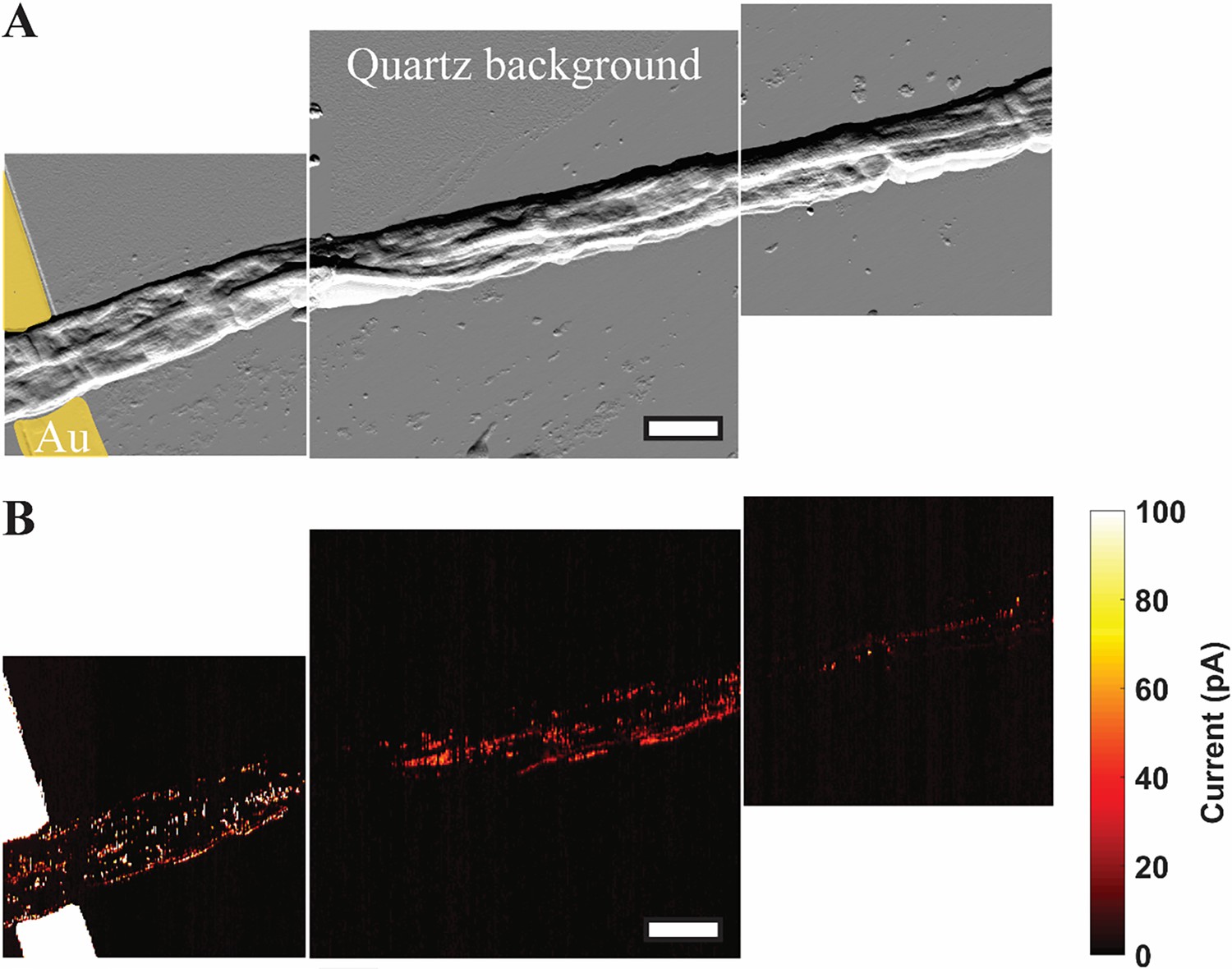
Mapping the conductive network of cable bacteria by conductive AFM.
(A) A spatial montage of three consecutive tapping atomic force microscopy amplitude images of two parallel Mungi Lake freshwater cable bacteria in contact with, and extending away from, an electrode (false colored yellow). Scale bar: 3 μm. (B) Conductive atomic force current map images of the same sections shown in (A) with 5 V bias between the underlying electrode and conductive tip. The observed current signals largely correlate with the corresponding cell surface ridge pattern in (A).
-
Figure 7—source data 1
The amplitude data of the conductive AFM mapping.
- https://cdn.elifesciences.org/articles/91097/elife-91097-fig7-data1-v1.zip
-
Figure 7—source data 2
The current data of the conductive AFM mapping.
- https://cdn.elifesciences.org/articles/91097/elife-91097-fig7-data2-v1.zip
-
Figure 7—source data 3
The amplitude data of the conductive AFM mapping.
- https://cdn.elifesciences.org/articles/91097/elife-91097-fig7-data3-v1.zip
-
Figure 7—source data 4
The current data of the conductive AFM mapping.
- https://cdn.elifesciences.org/articles/91097/elife-91097-fig7-data4-v1.zip
-
Figure 7—source data 5
The amplitude data of the conductive AFM mapping.
- https://cdn.elifesciences.org/articles/91097/elife-91097-fig7-data5-v1.zip
-
Figure 7—source data 6
The current data of the conductive AFM mapping.
- https://cdn.elifesciences.org/articles/91097/elife-91097-fig7-data6-v1.zip
Figure 8
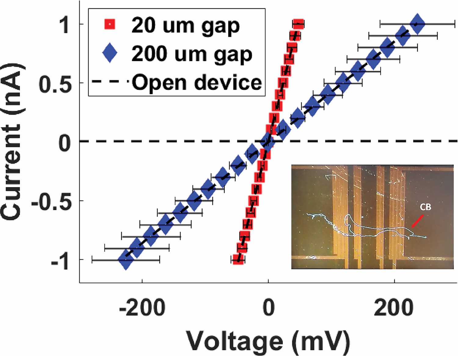
Four-probe current–voltage measurements of Mungi Lake freshwater cable bacteria filaments, shown for two different separations between the two inner probes.
Inset: representative image of cable bacteria filaments across a four-probe device. Each data point is the average of three data points, and the error bars represent the standard deviation.
-
Figure 8—source data 1
Four-probe measurement 1 on the cable over a 200-micron gap.
- https://cdn.elifesciences.org/articles/91097/elife-91097-fig8-data1-v1.xlsx
-
Figure 8—source data 2
Four-probe measurement 2 on the cable over a 200-micron gap.
- https://cdn.elifesciences.org/articles/91097/elife-91097-fig8-data2-v1.xlsx
-
Figure 8—source data 3
Four-probe measurement 3 on the cable over a 200-micron gap.
- https://cdn.elifesciences.org/articles/91097/elife-91097-fig8-data3-v1.xlsx
-
Figure 8—source data 4
Four-probe measurements on the cable over a 20-micron gap.
- https://cdn.elifesciences.org/articles/91097/elife-91097-fig8-data4-v1.xlsx
-
Figure 8—source data 5
Four-probe measurement 2 on the cable over a 20-micron gap.
- https://cdn.elifesciences.org/articles/91097/elife-91097-fig8-data5-v1.xlsx
-
Figure 8—source data 6
Four-probe measurement 3 on the cable over a 20-micron gap.
- https://cdn.elifesciences.org/articles/91097/elife-91097-fig8-data6-v1.xlsx
-
Figure 8—source data 7
Four-probe measurement 1 on the cable over a 20-micron gap.
- https://cdn.elifesciences.org/articles/91097/elife-91097-fig8-data7-v1.xlsx
Additional files
Download links
A two-part list of links to download the article, or parts of the article, in various formats.
Downloads (link to download the article as PDF)
Open citations (links to open the citations from this article in various online reference manager services)
Cite this article (links to download the citations from this article in formats compatible with various reference manager tools)
Long-distance electron transport in multicellular freshwater cable bacteria
eLife 12:RP91097.
https://doi.org/10.7554/eLife.91097.3


