Toxoplasma gondii peptide ligands open the gate of the HLA class I binding groove
- University of Oklahoma Health Sciences Center, United States
- Pure MHC LLC, United States
- Technical University of Denmark, Denmark
- La Jolla Institute for Allergy and Immunology, United States
- University at Buffalo School of Medicine, United States
- University of Chicago, United States
- Universidad Nacional de San Martín, Argentina
Figures
Figure 1
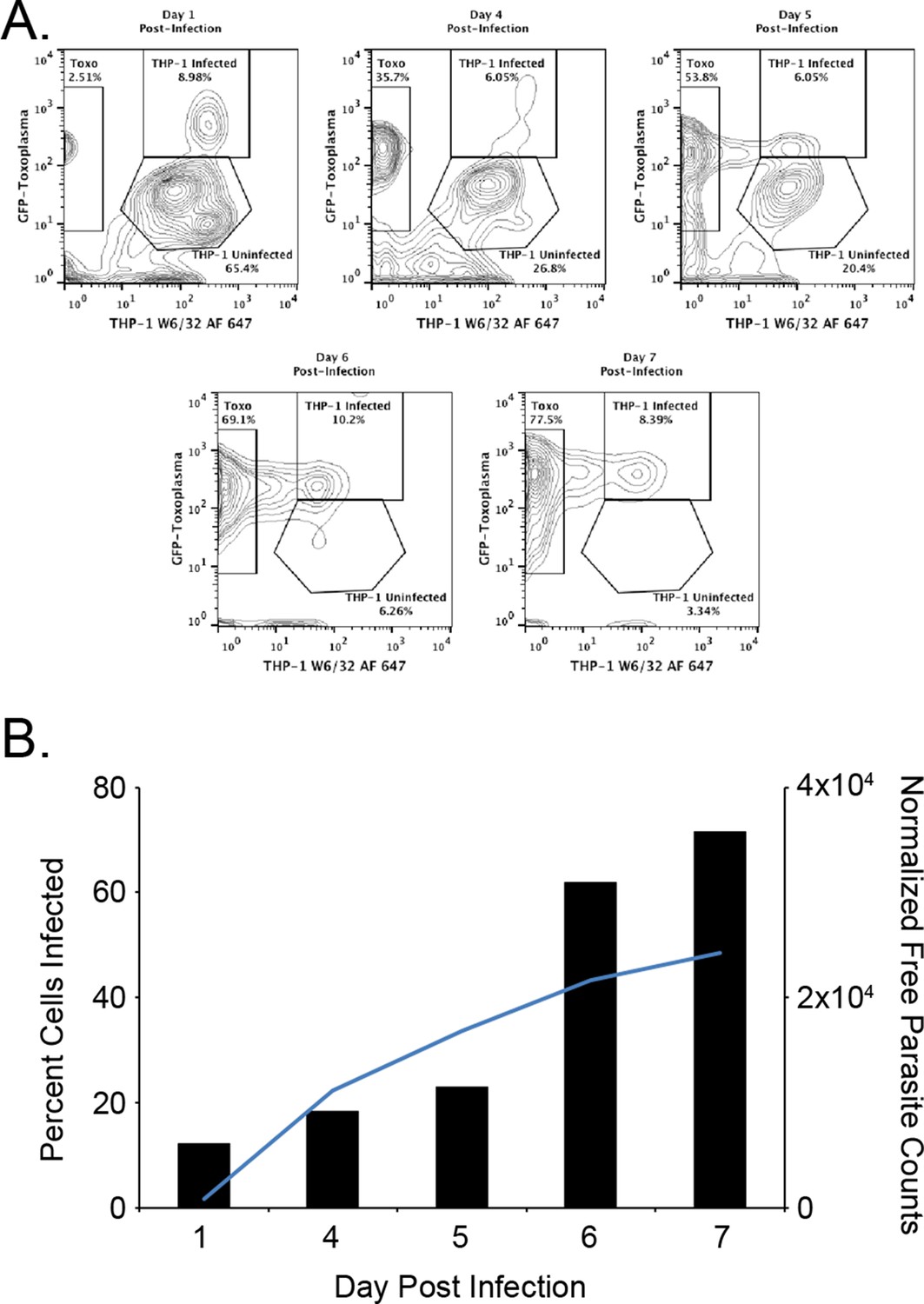
Kinetics of the T. gondii infection in the bioreactor production.
(A) Raw flow cytometry data and gates of the samples taken from the bioreactor on each indicated day post infection. (B) Histogram of the percent of infected cells (black bars) as well as the normalized free parasite counts (blue line). Raw parasite counts were normalized to the total counts of each respective experiment.
Figure 2

Sequence identity of identified T. gondii ligands to H. sapiens.
T. gondii derived sequences were BLAST searched against the NCBInr H. sapiens proteome. Sequence identity was recorded and ligands with <50% sequence identity were considered not significant and were binned together.
Figure 3 with 1 supplement
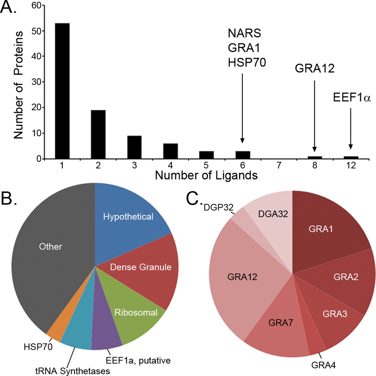
Ligand sampling of source proteins.
(A) The number of distinct ligands from a given source protein was counted binned by number of ligands. Gene symbols of the most sampled proteins are shown above the respective bin. (B) Distribution of ligands by source protein group or individual source protein. (C) Distribution of ligands by source dense granule protein.
-
Figure 3—source data 1
PEAKS export file containing HLA-A*02:01 peptide H. sapiens derived ligands from uninfected THP-1 cells.
- https://doi.org/10.7554/eLife.12556.006
Figure 3—figure supplement 1
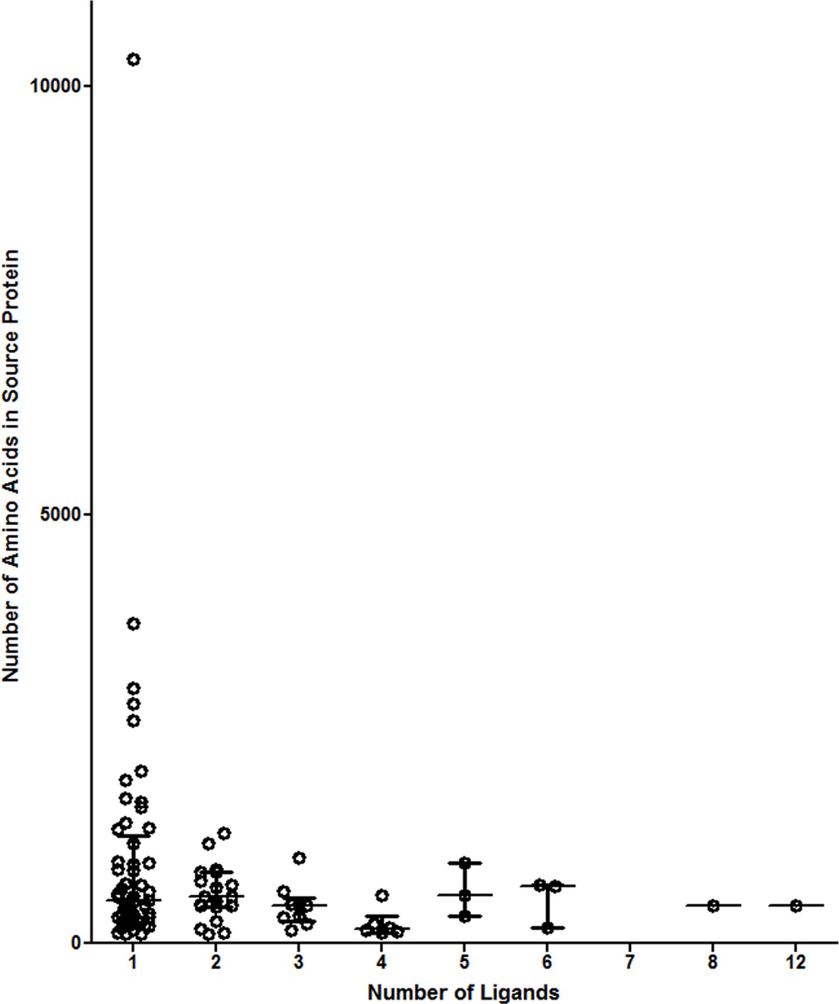
Number of ligands do not correspond to source protein length.
Proteins were binned by the number of ligands identified. The median values of the source protein length in each bin are shown.
Figure 4
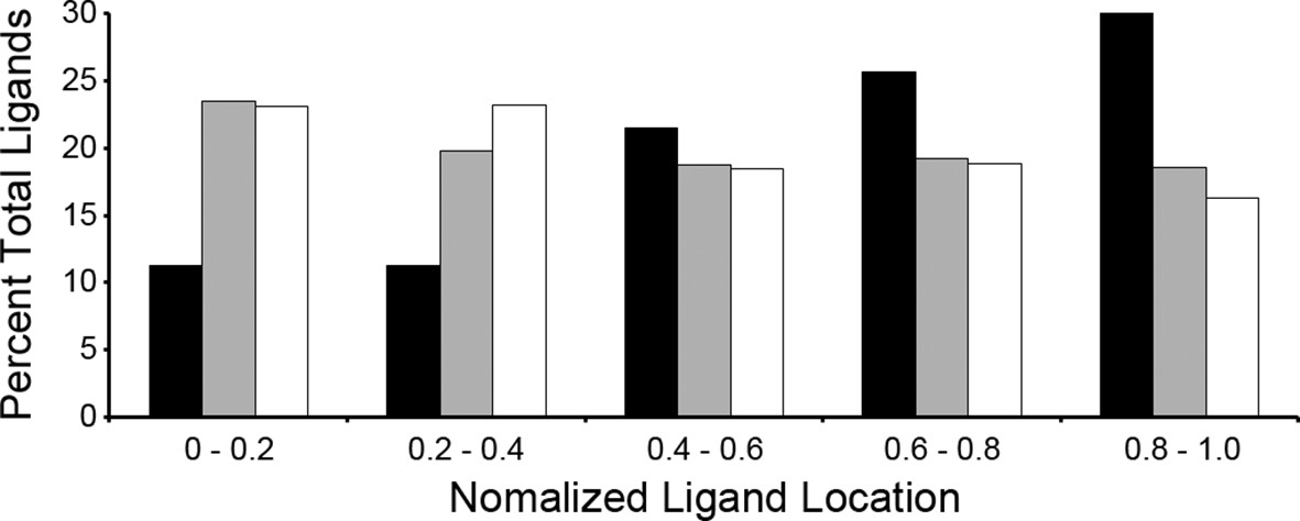
Location of ligands within respective source proteins.
Normalized ligand location within the respective source protein from the unambiguous T. gondii ligands (black), H. sapiens ligands from infected THP-1 cells (white) and, H. sapiens ligands from uninfected THP-1 cells (grey).
Figure 5
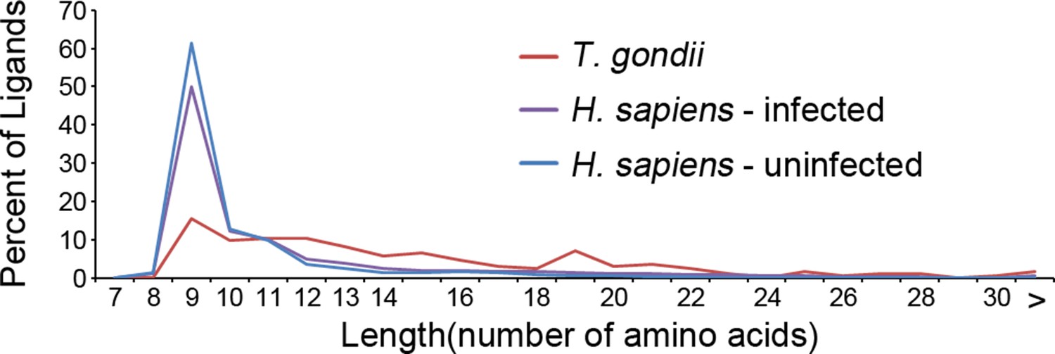
Length distribution of identified ligands.
Length distributions of unambiguous T. gondii ligands (red), H. sapiens ligands from infected THP-1 cells (purple) and, H. sapiens ligands from uninfected THP-1 cells (blue).
-
Figure 5—source data 1
PEAKS export file containing HLA-A*02:01 peptide T. gondii derived ligands from T. gondii infected THP-1 cells.
- https://doi.org/10.7554/eLife.12556.010
-
Figure 5—source data 2
PEAKS export file containing HLA-A*02:01 peptide H. sapiens derived ligands from T. gondii infected THP-1 cells.
- https://doi.org/10.7554/eLife.12556.011
Figure 6
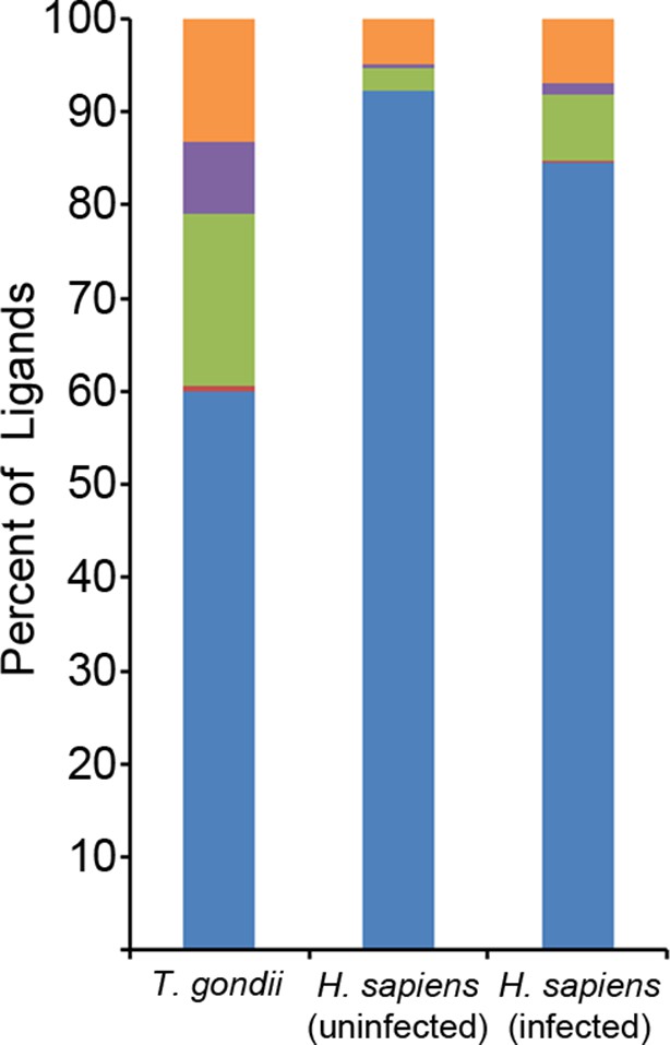
Binding prediction analysis of eluted ligands.
Percentage of total ligands in indicated dataset that are predicted to be canonical binders (blue), contain a C-terminal binding core (red), contain an N-terminal binding core (green), contain a central binding core (purple), or not predicted to bind (orange).
Figure 7
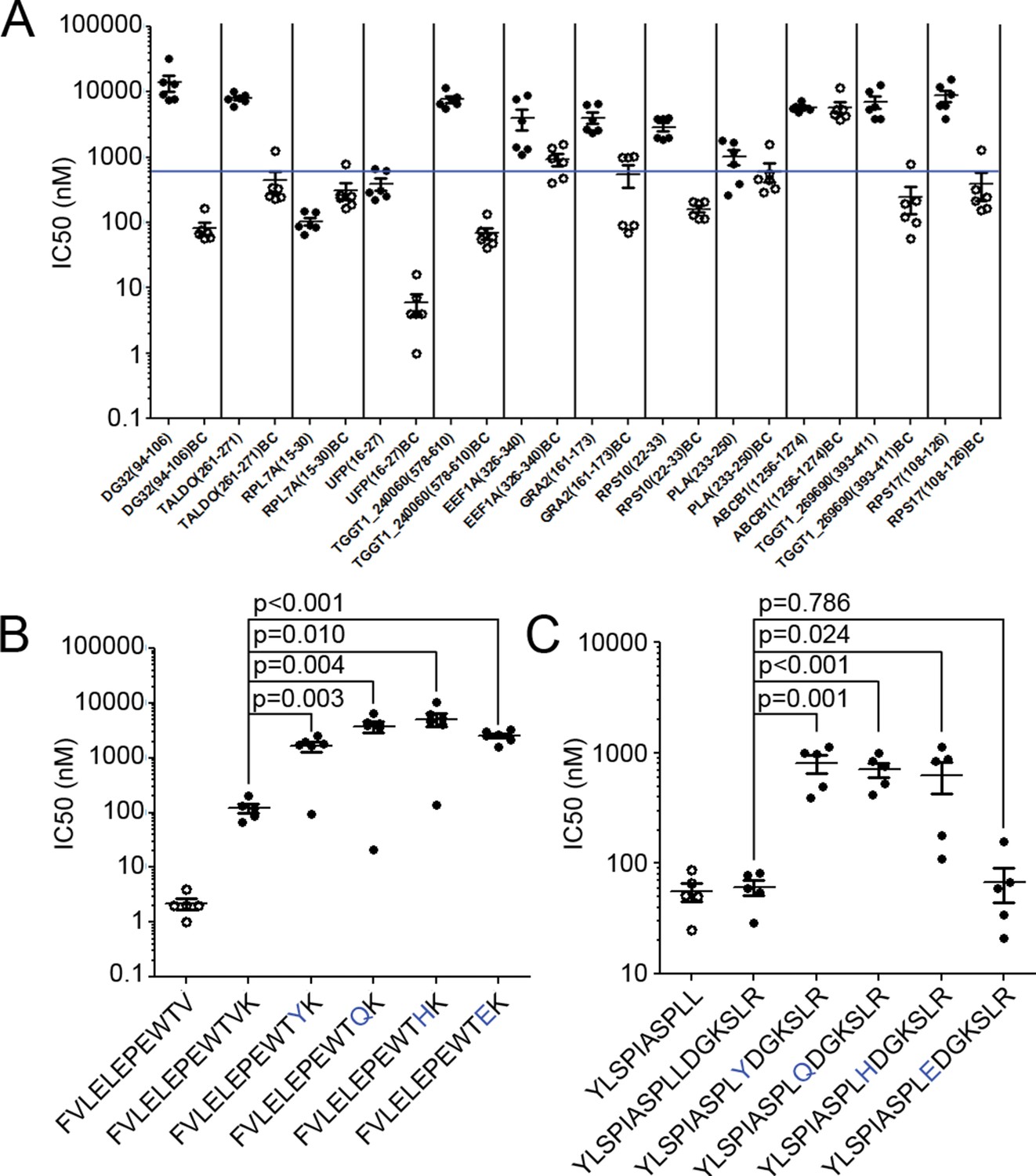
Binding affinity of extended ligands and their respective binding cores.
(A) Measured IC50 of extended peptides (black fill) and the respective predicted binding core (white fill). Blue line denotes 500 nM; binding affinities below this are considered binders. (B, C) Mutation analysis of FVLELEPEWTVK and YLSPIASPLLDGKSLR with non-permissive F’ pocket residues. Blue letters denote the mutated residue. All data shown are the results of two independent experiments run in triplicate or duplicate. P-values shown are the result of an unpaired two-tailed t-test.
Figure 8
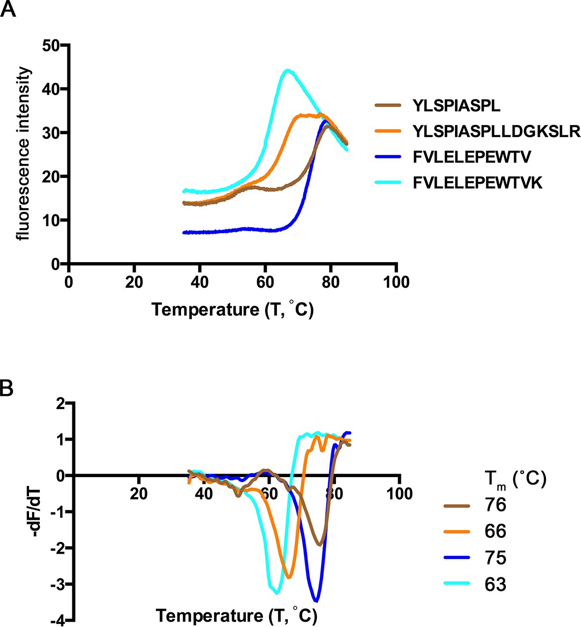
Thermal denaturation of extended ligands.
(A) Raw fluorescence of the melt curve for indicated peptide/HLA-A*02:01 complex. (B) First derivative of the melt curve from thermal denaturation experiment for HLA-A*02:01 indicated peptide ligand. The melting temperature for each peptide was calculated from the minima of these curves and is shown in the figure legend.
Figure 9
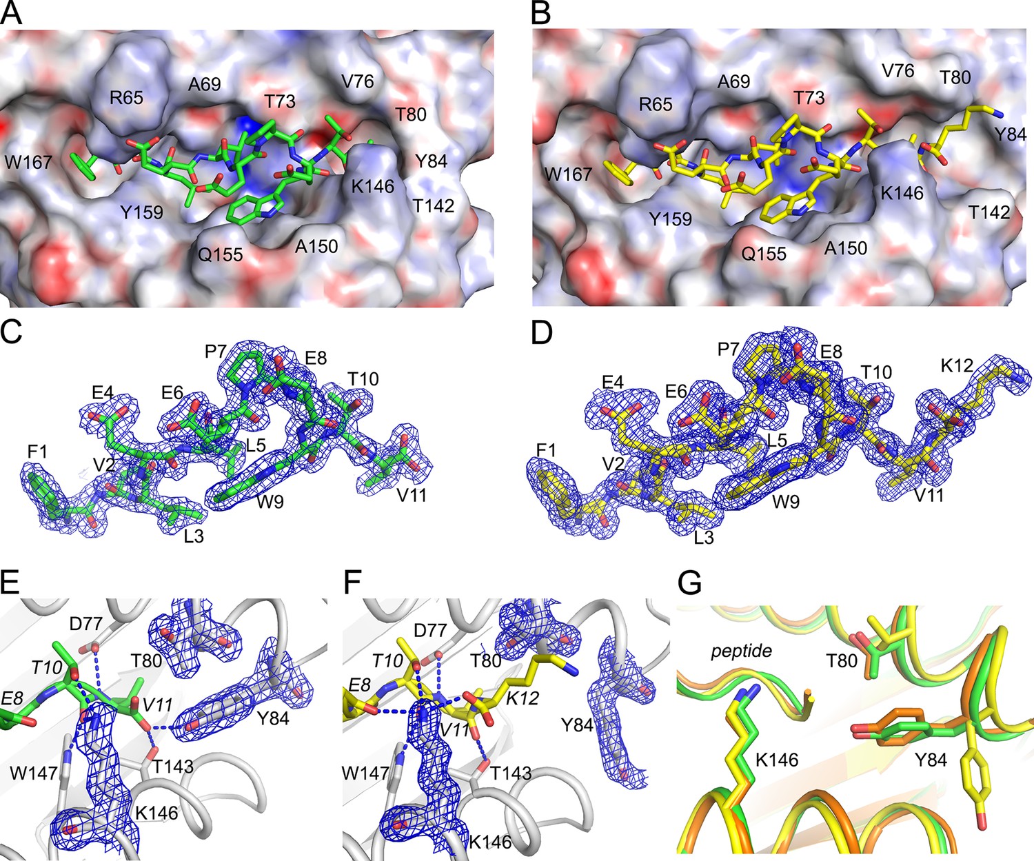
Structural details of extended ligand binding to HLA-A*02:01.
Binding of core peptide FVLELEPEWTV (A, C, E) and extended ligand FVLELEPEWTVK (B, D, F) to HLA-A*02:01. Peptides are shown as sticks, while HLA-A*02:01 is shown as a molecular surface with electrostatic potential contoured from -30kT/E to +30kT/E (positive charge in blue, negative in red). Peptide FVLELEPEWTV in green, and FVLELEPEWTVK in yellow. 2FoFc electron density is shown as a blue mesh around the peptide (2 Å radius) FVLELEPEWTV (C) and FVLELEPEWTVK (D) and contoured at 1σ Details of peptide binding to the F’ pocket of MHC (E, F). MHCI residues that form H-bond interactions (blue dashed lines) with the peptide are labeled. MHC residues that are critical for the F’ pocket formation are shown with electron density with same settings as in C and D. (F) Note how Thr80 (T80) and Tyr84 (Y84) change position upon binding of extended ligand FVLELEPEWTVK. Those structural changes are not seen in PDB ID 2CLR (orange) when superimposed with UFP (16–26) and UFP (16–27).
Additional files
-
Supplementary file 1
Species ambiguous ligands.
- https://doi.org/10.7554/eLife.12556.016
-
Supplementary file 2
Identified unambiguous T. gondii ligands.
- https://doi.org/10.7554/eLife.12556.017
-
Supplementary file 3
Predicted extended ligands and binding cores.
Bold sequences indicate the peptides selected for the binding assay.
- https://doi.org/10.7554/eLife.12556.018
-
Supplementary file 4
Data collection and refinement statistics for crystal structures.
- https://doi.org/10.7554/eLife.12556.019
Download links
A two-part list of links to download the article, or parts of the article, in various formats.
Downloads (link to download the article as PDF)
Open citations (links to open the citations from this article in various online reference manager services)
Cite this article (links to download the citations from this article in formats compatible with various reference manager tools)
Toxoplasma gondii peptide ligands open the gate of the HLA class I binding groove
eLife 5:e12556.
https://doi.org/10.7554/eLife.12556


