The role of scaffold reshaping and disassembly in dynamin driven membrane fission
- Carnegie Mellon University, United States
Figures
Figure 1
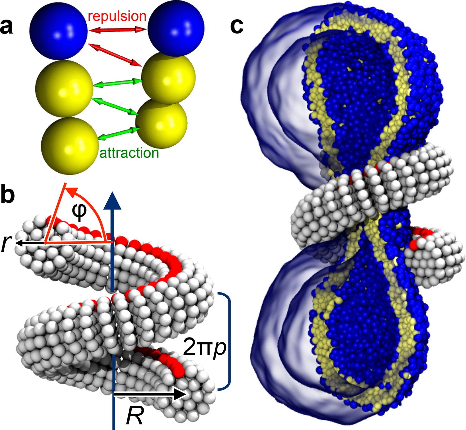
Ingredients of the model.
(a) CG lipids comprising three beads assemble into membranes via tail bead attractions and head bead repulsions. (b) the dynamin helix is built as a stack of disks with 19 CG beads each; it contains an adhesive membrane-binding strip (red) that represents the PH domains and that can rotate by an angle away from the inward-pointing direction. (c) a CG filament constricts the neck of a CG vesicle consisting of CG lipids.
Figure 2 with 1 supplement
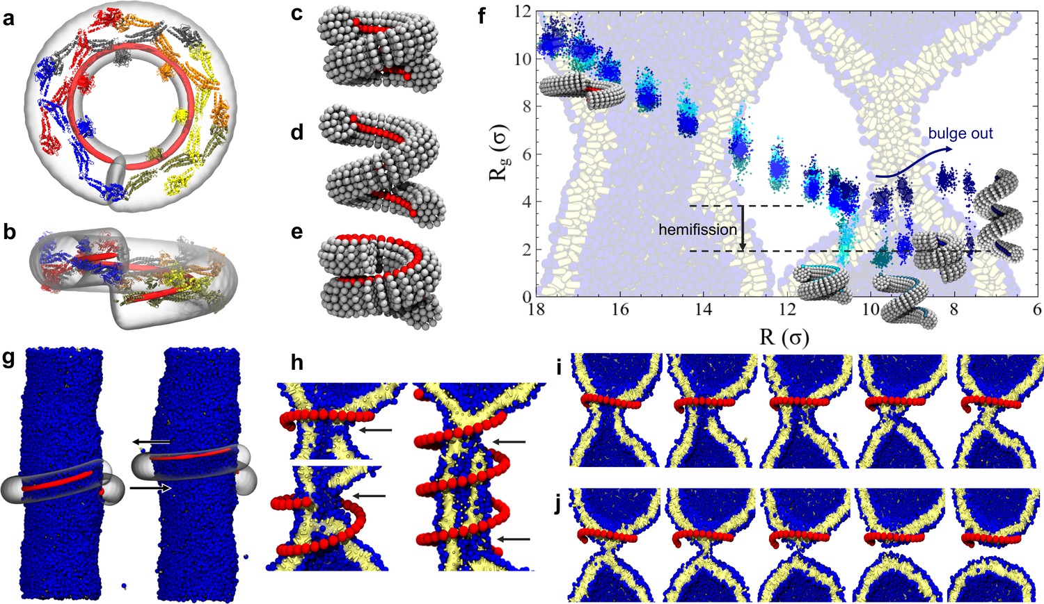
Dynamin shape changes and membrane response.
(a) Top and (b) Side-view of dynamin dimers assembled into an unconstricted helical filament. (c) CG representation of a constricted filament. (d) Constricted and elongated filament. (e) Constricted and rotated filament. (f) Radius of gyration of the membrane neck (see Materials and methods section) as a function of filament radius under four protocols: constriction only (blue) constrictionrotation (cyan), constrictionrotationelongation (dark cyan), constrictionelongation (dark blue). (g) An unconstricted filament resting on a membrane of matching radius (left) creates a Darboux-torque once the (red) adhesion strip is rotated (right), inducing the membrane to asymmetrically bulge; the two arrows indicate the torque couple. (h) Cross-sectional view of a 1- and 1.5-turn helical scaffold at and a 3.5-turn scaffold at . The filament was constricted and rotated, only the adhesion strip is shown. Hemifission seeds are small pores, visible as breaks in bilayer continuity (arrows). (i) Cross-cut illustration of membrane shape changes triggered by a simultaneous filament constriction, rotation, and gradual disassembly (Video 5), leading to hemifission. (j) Continuation of the previous sequence from hemifission to complete fission.
-
Figure 2—source data 1
Constriction-elongation trajectory.
- https://doi.org/10.7554/eLife.39441.010
-
Figure 2—source data 2
Constriction-rotation-elongation trajectory.
- https://doi.org/10.7554/eLife.39441.011
-
Figure 2—source data 3
Constriction-rotation trajectory.
- https://doi.org/10.7554/eLife.39441.012
-
Figure 2—source data 4
Pure constriction trajectory.
- https://doi.org/10.7554/eLife.39441.013
Figure 2—figure supplement 1
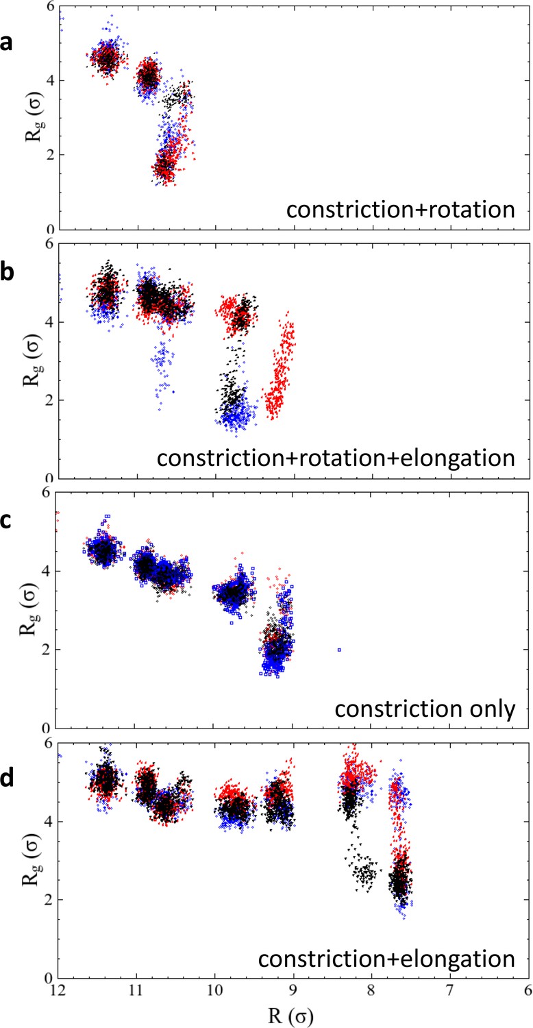
Results of repeated simulation trajectories for the four different constriction protocols presented in Figure 2f.
The black dots are the same data as shown in the main article, the red and blue dots stem from two additional runs. In the two cases of constriction and constriction + rotation, all three trajectories transition into the hemifission state at exactly the same constriction step, while the cases constriction + elongation and constriction + rotation + elongation exhibit some scatter. We attribute this to the larger freedom that the enclosed membrane has in a helical scaffold that features an ever-widening groove due to the elongation component of the shape transformation. Figure 2—source data 1. The data from panel 2 f, as well as the repeated runs shown in Figure 2—figure supplement 1, are given as text-files containing as a function of for all four constriction scenarios.
-
Figure 2—figure supplement 1—source data 1
Constriction-elongation trajectories.
- https://doi.org/10.7554/eLife.39441.006
-
Figure 2—figure supplement 1—source data 2
Constriction-rotation-elongation trajectories.
- https://doi.org/10.7554/eLife.39441.007
-
Figure 2—figure supplement 1—source data 3
Constriction-rotation trajectories.
- https://doi.org/10.7554/eLife.39441.008
-
Figure 2—figure supplement 1—source data 4
Pure constriction trajectories.
- https://doi.org/10.7554/eLife.39441.009
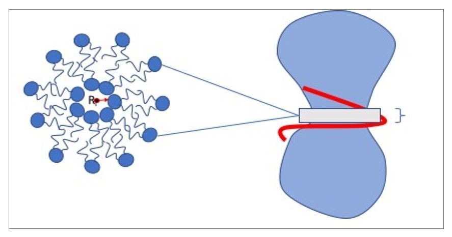
Box 1—Figure 1
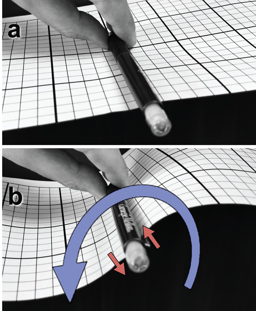
Illustration of a tangential membrane torque.
https://doi.org/10.7554/eLife.39441.016
Figure 3
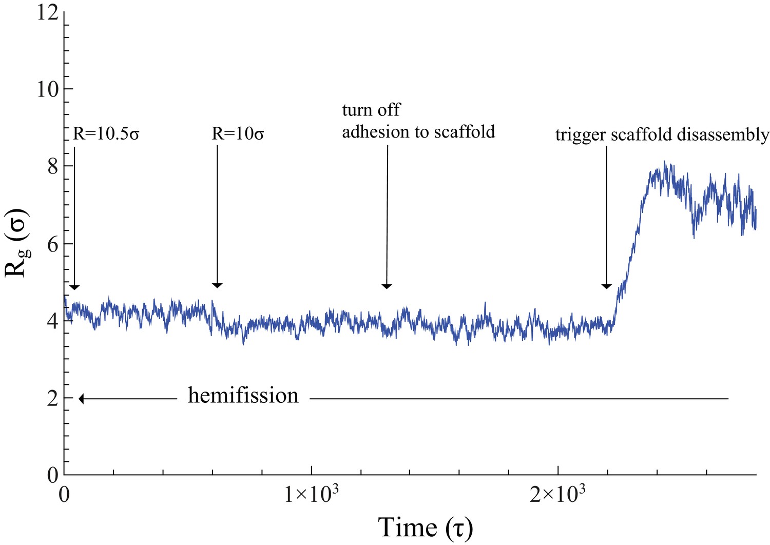
Time evolution of .
The neck’s gyration radius is shown in the end stages of a pure constriction protocol. The time series starts when the scaffold radius is , which leads to (as measured over the subsequent , with an error determined via blocking (Flyvbjerg and Petersen, 1989)). After that, a further constriction of the filament to reduces the neck’s gyration radius to but does not trigger hemifission (which corresponds to the much smaller value —see Figure 2f). Turning off the adhesion between scaffold and membrane only reduces the gyration radius by a very minor amount, , a change that is not statistically significant (). Once we additionally let the scaffold disassemble into (non-adhesive) dimers (see also Video 4), the neck very rapidly doubles its radius within about , after which the definition of its location becomes ambiguous.
-
Figure 3—source data 1
Gyration radius as a function of time.
The data are available as a text-file containing as a function of .
- https://doi.org/10.7554/eLife.39441.019
Figure 4

Hemifission via a transient pore.
This time sequence of simulation snapshots shows slices through the membrane neck with a width of , placed symmetric around the center of mass of the scaffold (not shown for clarity). The continuity of the tail region (yellow; blue are the head groups) is emphasized by using VMD’s ‘QuickSurf’ rendering on all tail beads (Humphrey et al., 1996), which creates an isosurface extracted from a volumetric Gaussian density map. In panel (a), chosen to be time-point in this sequence, the tail region is still continuous and encloses an inner lumen with a diameter of about . In panel (b) a small pore opens (red arrow) that connects the inner lumen to the exterior region of the vesicle. As it widens through panels (c) and (d), the pore rim above and below the imaged plane fuses to the inner leaflet of the lumen, which finally leaves in panel (e) a cylindrical hemifission micelle connecting two closed vesicles. See also Video 2.
Figure 5
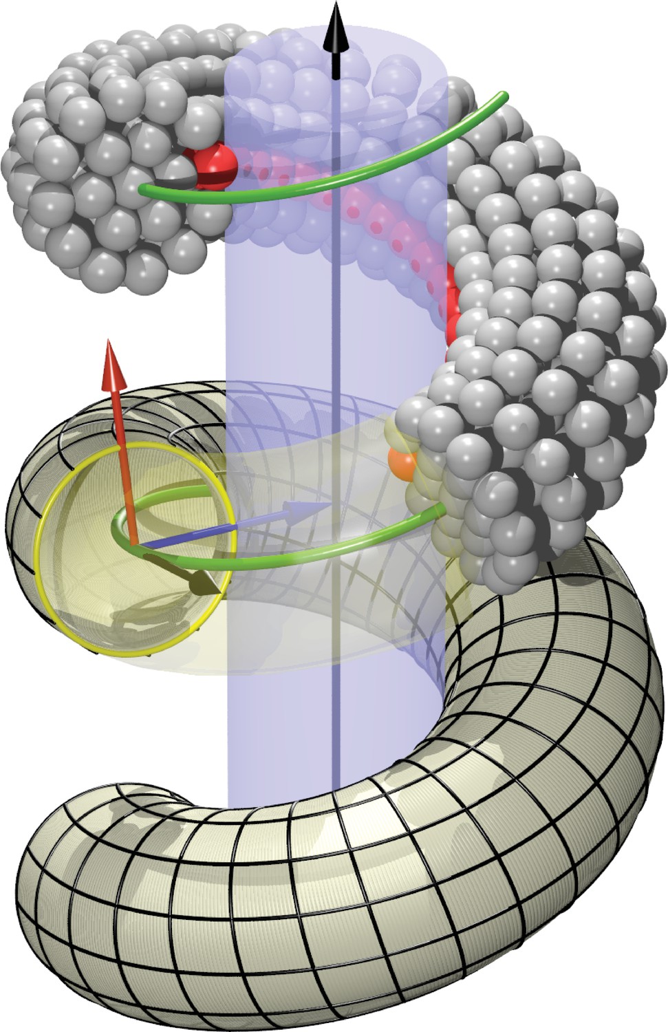
Definition of helicoidal coordinate system.
The black vertical -axis is surrounded by a cylinder, around which a helical dynamin tube winds. Its green center line with radius and pitch is given by (Equation 1). On this space curve we define the (right-handed) Darboux-frame , consisting of a tangent vector (black), normal vector (blue) and co-normal vector (red), which are given by (Equation 2). In the --plane we can then define the circular cross-section of the filament and place rings of CG beads at the correct distance from the green filament axis. The direction along points towards the enclosed cylinder, but it is easy to rotate it by an angle around the axis. This is how one may rotate the beads representing the PH domain (red) off the underlying substrate.
Figure 6
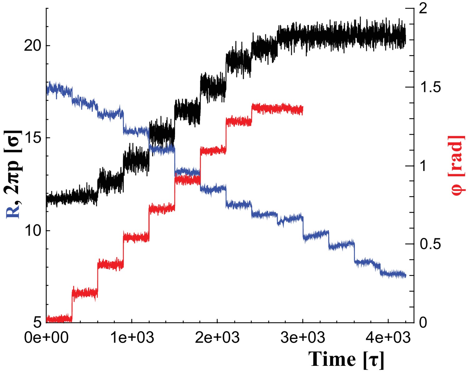
Changes of filament geometry.
Time sequence followed when driving the dynamin filament through changes in its radius , pitch , and rotation angle . As detailed in the results section, we conduct sets of simulations in which various combinations of these observables are adjusted, while others stay at their original value. For instance, in a constrictionelongation simulation the radius is successively decreased from to , while the pitch is simultaneously tuned up from to in a way documented by the blue and black curves, respectively, while the rotation angel remains at .
-
Figure 6—source data 1
Angle as a function of time.
The data are available as text-files containing , , and as a function of time .
- https://doi.org/10.7554/eLife.39441.027
-
Figure 6—source data 2
Pitch as a function of time.
- https://doi.org/10.7554/eLife.39441.028
-
Figure 6—source data 3
Radius as a function of time.
- https://doi.org/10.7554/eLife.39441.029
Author response image 1
Videos
Video 1
Pure filament constriction.
A dynamin filament, initially with radius , pitch and rotation angle is constricted by stepwise reduction of the radius down to the critical radius , following the blue time-series in Figure 6. The right part of the video shows a side view, in which the 10,000 lipids of the vesicle are only rendered in stick-representation such as to permit some amount of transparency. The dynamin filament is shown as a transparent gray tube, and only the adhesive PH domain strip is explicitly shows as a sequence of red beads. The left part of the video shows a view along the helical axis of the filament, and lipids are only shown if their -distance from the filaments center of mass is within , such as to follow the extent of constriction and the diameter of the luminal region.
Video 2
Filament constriction and rotation.
Same as Video 1, but this time the filament is additionally rotated, following a combination of the blue and red time series in Figure 6. The hemifission event towards the end happens at , at which the non-rotation protocol shown in Video 1 does not lead to hemifission. It results in a stable cylindrical micelle spanning the two daughter vesicles.
Video 3
Filament breakage with retained adhesion.
A filament constricting a vesicle down to the critical radius is suddenly cut into pieces comprising five discs each (corresponding roughly to dynamin dimers). Even though the membrane curving fragments retain their adhesion energy with respect to the membrane substrate, this leads to a re-expansion of the neck radius, followed later by fragment unbinding once the substrate curvature becomes too unfavorable.
Video 4
Filament breakage with simultaneously lost adhesion.
Same as Video 3, except that the fragments also lose their binding affinity to the membrane, causing them to immediately detach and stop curving the substrate.
Video 5
Constriction, rotation, and concurrent filament depolymerization.
Same as Video 2, except that the filament also concurrently depolymerizes during constriction and rotation. As a result, once hemifission sets in, the two point-defects at the ends of the resulting cylindrical hemifission micelle are no longer kept far apart by the now much shorter enclosing scaffold, permitting the defects to annihilate and thus fission to complete.
Video 6
Fission via unbinding and defect merger.
If at the endpoint of Video 2 the filament depolymerizes, the cylindrical hemifission micelle pulls the two daughter vesicles together and permits the point defects to merge and annihilate, thus completing fission.
Additional files
-
Transparent reporting form
- https://doi.org/10.7554/eLife.39441.030
Download links
A two-part list of links to download the article, or parts of the article, in various formats.
Downloads (link to download the article as PDF)
Open citations (links to open the citations from this article in various online reference manager services)
Cite this article (links to download the citations from this article in formats compatible with various reference manager tools)
The role of scaffold reshaping and disassembly in dynamin driven membrane fission
eLife 7:e39441.
https://doi.org/10.7554/eLife.39441


