Structural insights into flagellar stator–rotor interactions
- Yale University School of Medicine, United States
- Yale University, United States
- East Carolina University, United States
- McGovern Medical School at University of Texas Health Science Center at Houston, United States
Figures
Figure 1 with 2 supplements
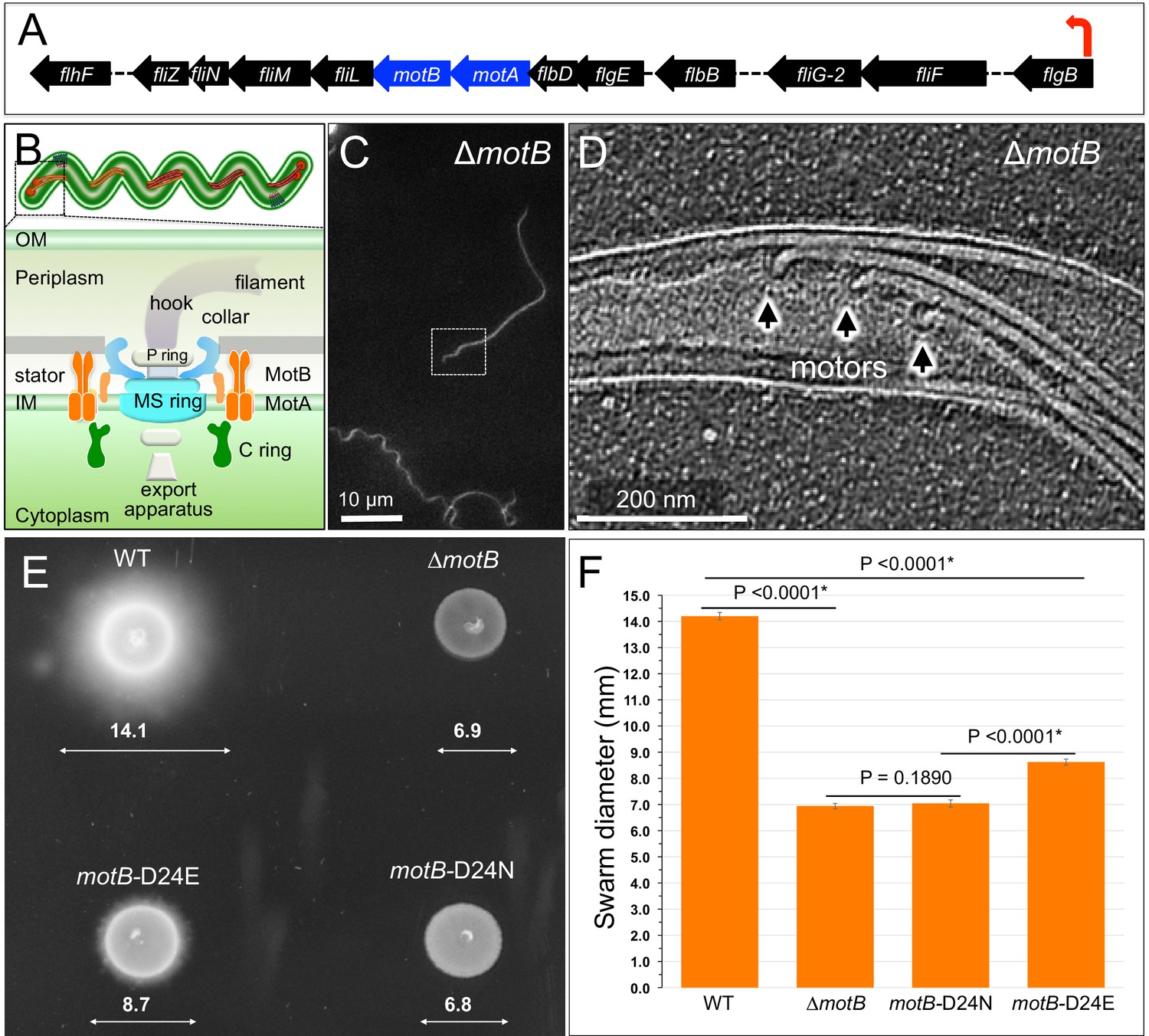
Overview of flagellar organization in Borrelia burgdorferi and the motility phenotypes of WT, ΔmotB, and point mutants of motB.
(A) Schematic of the flgB flagellar operon map of B. burgdorferi. Red arrow indicates the direction of transcription. The motA and motB genes are shown as blue arrows. (B) Schematic models of the periplasmic flagellum and the motor in a spirochete cell. (C) A dark-field microscopy image of a ΔmotB cell. (D) A section from a typical tomogram of a ΔmotB cell tip shows multiple flagellar motors and filaments in situ. (E) Swarm plate assay of WT, ΔmotB, motB-D24E, and motB-D24N cells. (F) Averages ± standard deviations of swarm diameters from WT, ΔmotB, motB-D24E and motB-D24N strains. A paired Student’s t test was used to determine a P value. P<0.05 between strains is considered significant.
Figure 1—figure supplement 1
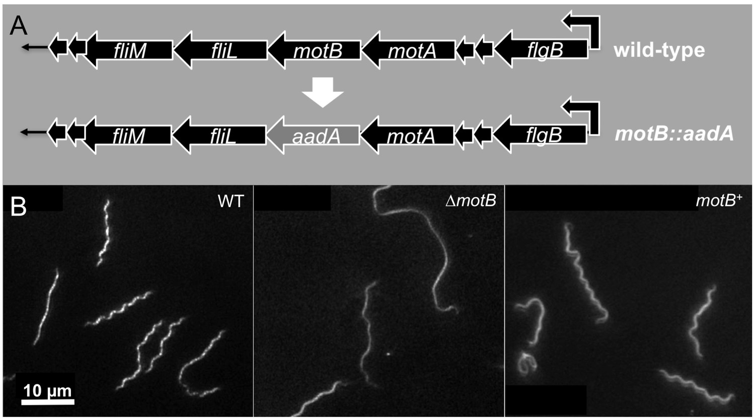
Construction and characterization of ∆motB and motB complementation.
(A) Construction of ∆motB and motB complementation in B. burgdorferi. (B) Cell morphologies of B. burgdorferi WT, ∆motB and motB complemented (motB+) cells.
Figure 1—figure supplement 2
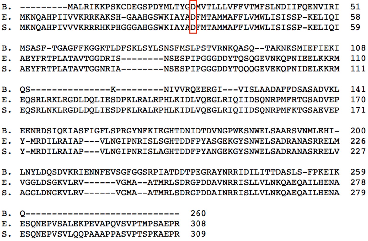
Sequence alignment of MotB proteins from three bacteria: B. burgdorferi (B.), E. coli (E.) and S. enterica (S.).
The conserved aspartic acid residue D (24 in B. burgdorferi, 32 in E. coli and 33 in S. enterica) is highlighted by red frame.
Figure 2 with 1 supplement

Asymmetric reconstructions of the ∆motB and WT motors in B. burgdorferi.
(A) A central section of the flagellar motor structure from a ∆motB mutant. The diameter of the bottom of the C-ring is 56 nm. The missing densities compared to the WT flagellar motor are indicated by empty yellow arrows. (B) A cross-section at the top of the C-ring from the ∆motB flagellar motor structure. The diameter of the top of the C-ring is 59 nm. (C) A cartoon model highlights key components in the ∆motB flagellar motor: C-ring (green), export apparatus (EXP), MS-ring (blue-green) embedded in the inner membrane (IM), FliL (coral), collar (light blue), P-ring (gray), and rod (blue). (D) A central section of the flagellar motor structure from WT. The diameter of the bottom of the C-ring is 56 nm. The extra densities compared to ∆motB flagellar motor structure are indicated by solid orange arrows. (E) A cross-section at the top of the C-ring from the WT flagellar motor structure. The diameter of the top of C-ring is 57 nm. Note that there are sixteen stator densities associated with the C-ring. The diameter of the stator ring is 80 nm. (F) A cartoon model highlights key flagellar components in the WT flagellar motor: C-ring, MS-ring, FliL, collar, and stators. Scale bar = 20 nm.
Figure 2—figure supplement 1
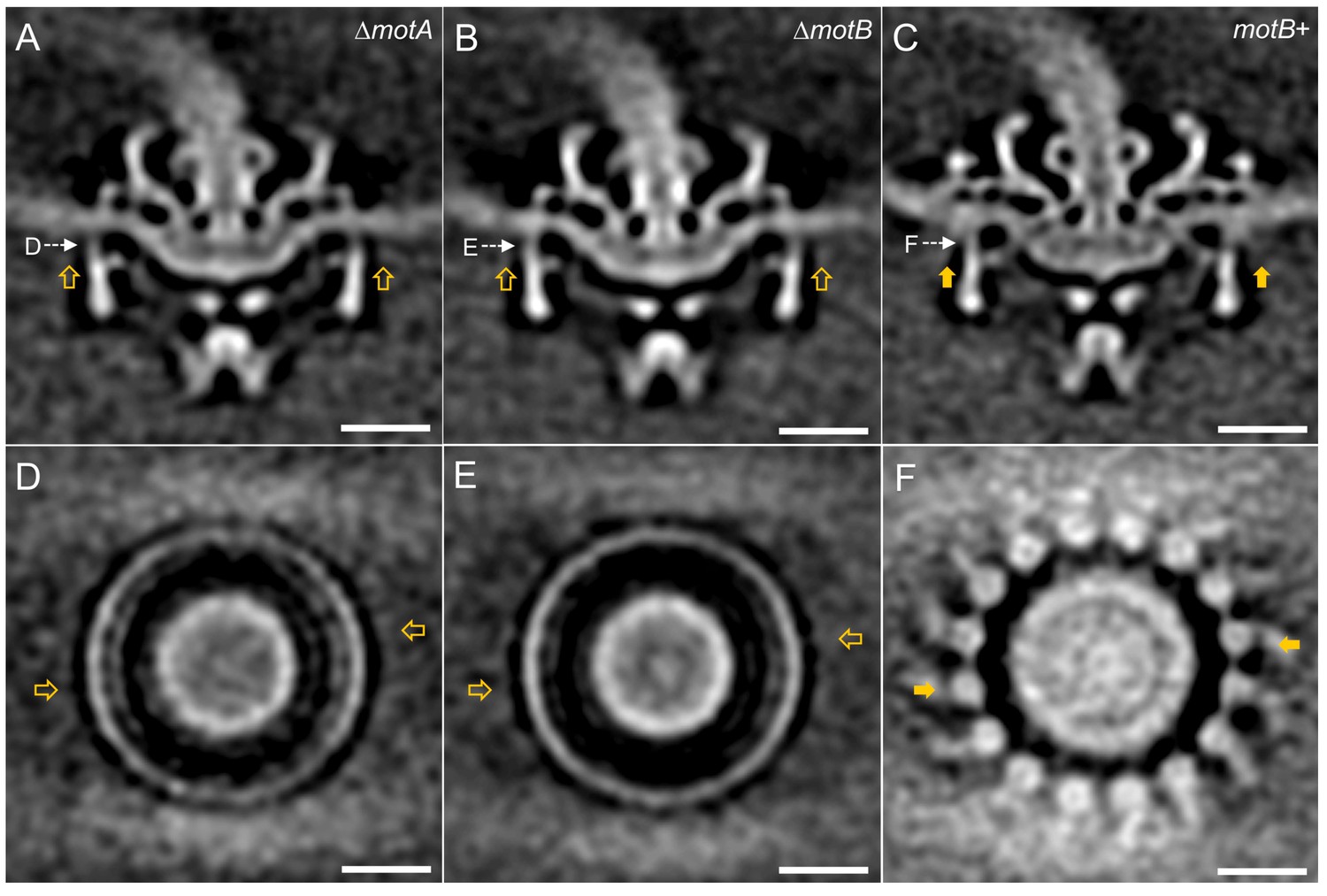
Asymmetric reconstructions of ∆motA, ∆motB and motB+ motors in B. burgdorferi.
(A-C) A central section of the asymmetric reconstruction of the ∆motA, ∆motB and motB+ motor structure, respectively. (D-E) A cross section from the asymmetric reconstruction of ∆motA, ∆motB and motB+ motor structure at the top of the C ring, respectively. Two stator complexes in motB+ motor structure are indicated by solid arrows, and the corresponding positions in ∆motA and ∆motB are indicated by empty arrows. Bar = 20 nm.
Figure 3 with 1 supplement
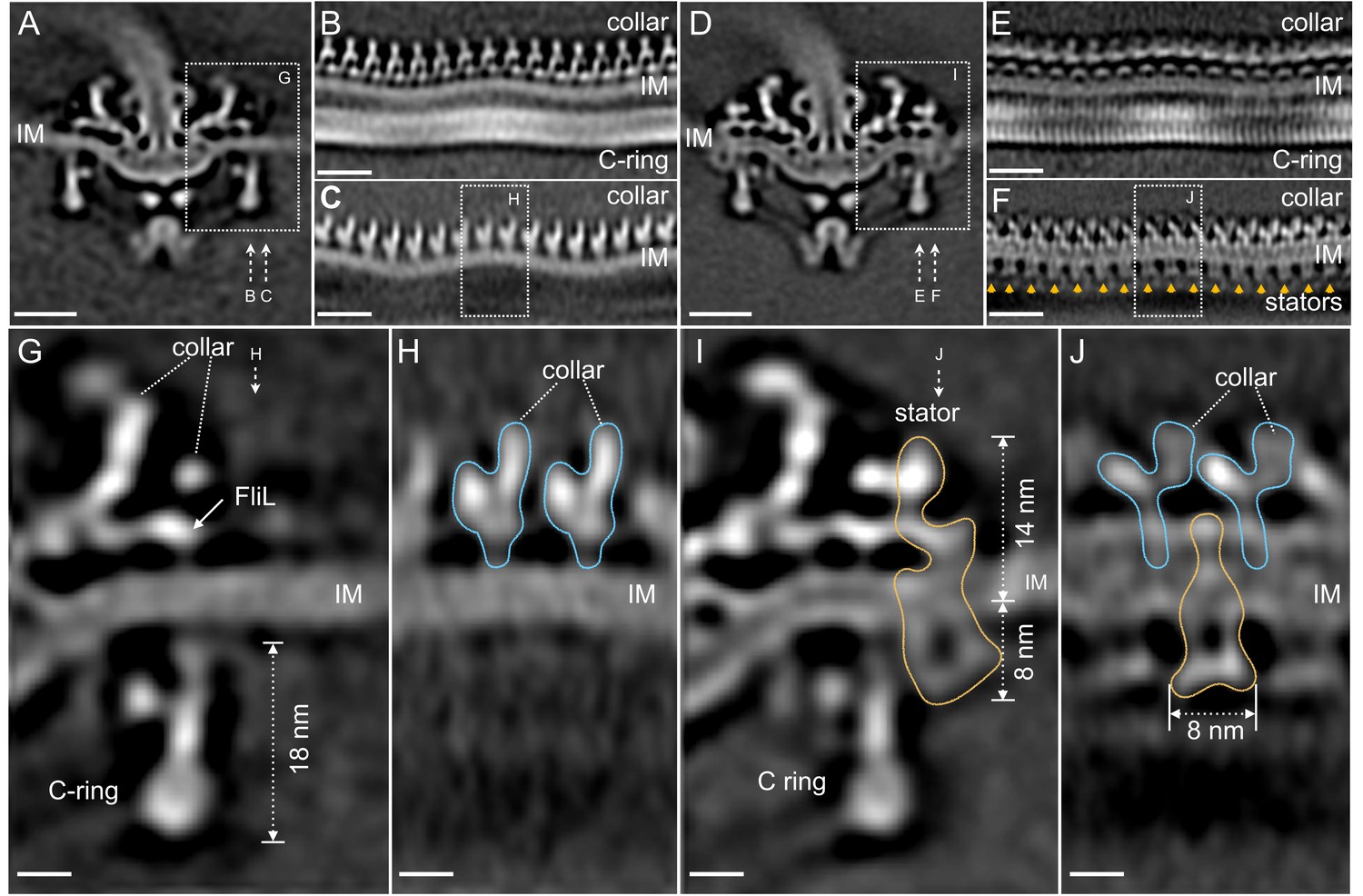
Visualization of the stator complexes and their interactions with the flagellar periplasmic components and the C-ring.
(A) A central section of the ∆motB motor structure. (B, C) Two sections from an unrolled map of the ∆motB motor showing the curvature of the inner membrane (IM), the collar and the C-ring, respectively. (D) A central section of the WT motor structure. (E) One section from the unrolled map of the refined C-ring of the WT motor showing the symmetry mismatch between the C-ring and the collar. (F) Another section from the unrolled map of the WT motor (D) showing sixteen stator complexes (indicated by orange arrows) embedded in the IM. (G) A central section from a refined structure of the ∆motB motor showing the C-ring, collar and FliL embedded in the IM. (H) A perpendicular section showing the collar (blue line highlighted) on top of the IM. (I) A central section from a refined structure of the WT motor showing the C-ring, and the stator complex (gold line). (J) A perpendicular section showing the stator complex (gold line) inserted between two subunits of the collar (highlighted by blue lines). Scale bar in panels A-F is 20 nm. Scale bar in panels G-J is 20 nm.
Figure 3—figure supplement 1
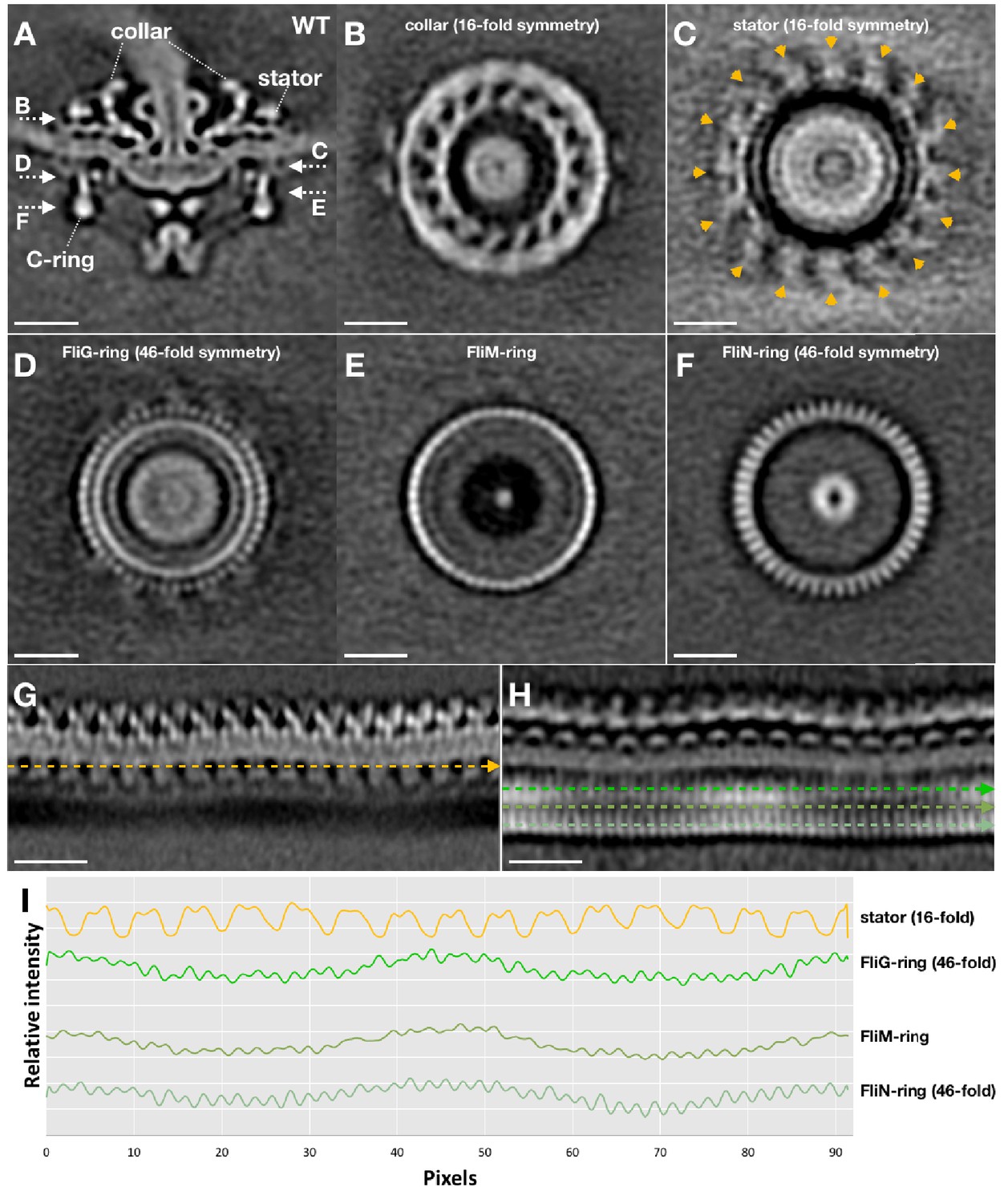
Symmetry analysis of the stator and the C-ring in WT motor structure.
After we got the asymmetric reconstruction of the WT motor structure (as shown in Figure 2D), the C-ring part was further refined to determine its symmetry. The C-ring refined WT motor structure is show in (A). After the C-ring refinement, the collar (B) and the stator ring (C) become blur (compare C with Figure 2E), but their 16-fold symmetries are still visible. While the 46-fold symmetries of the FliG-ring (D) and FliN-ring (F) are quite clear. (G) A section of the unrolled WT motor structure to show the stator (unrolled from the motor structure shown in Figure 2D). (H) A section of the unrolled WT motor structure to show the C-ring (unrolled from the motor structure shown in A). (I) Intensity plot files along the stator, FliG, FliM and FliN densities (indicated by dashed lines in G and H) showing their symmetries.
Figure 4 with 4 supplements
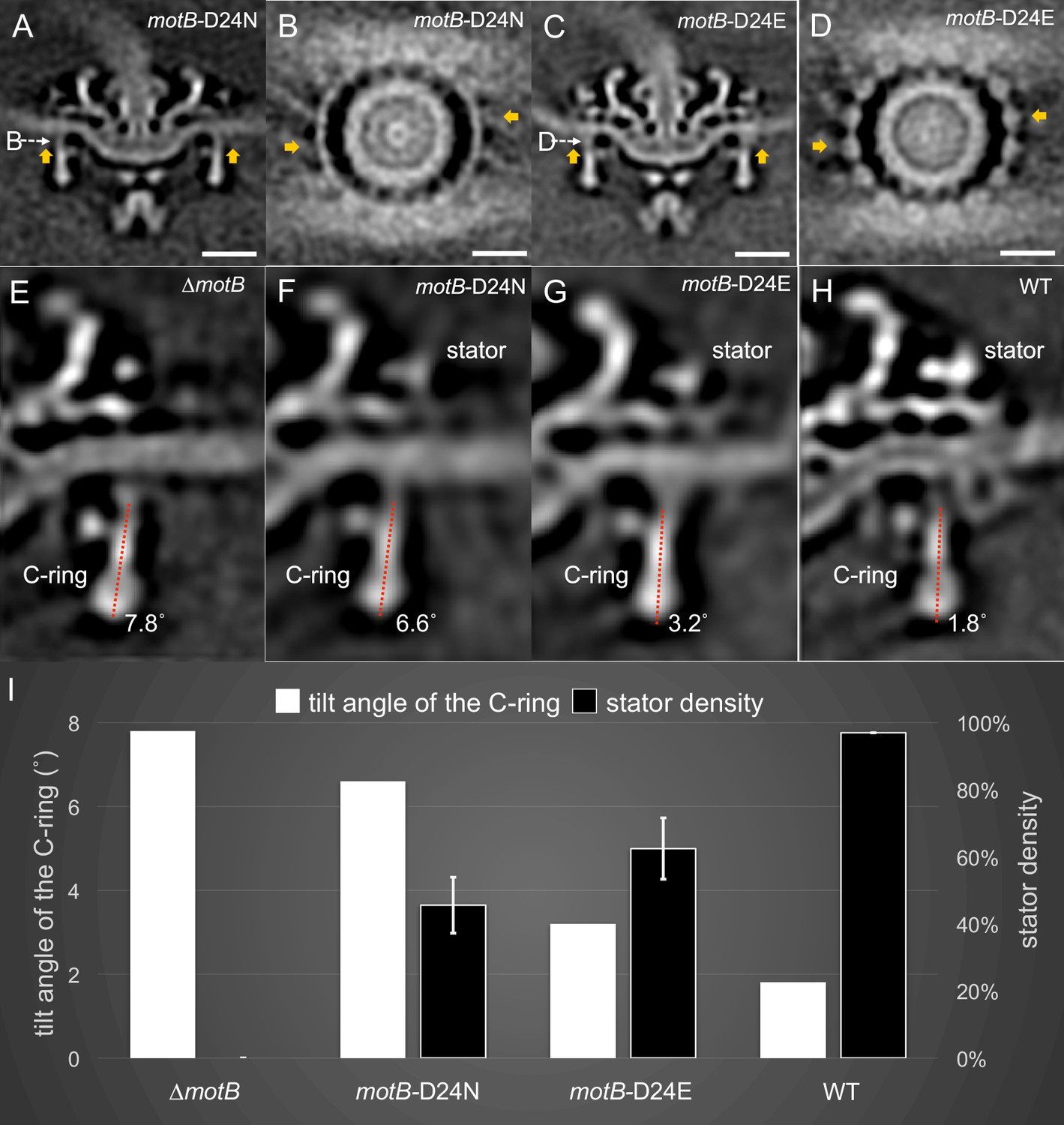
Stator binding and proton flux are required to induce the conformational changes of the C-ring.
(A) A central section from the asymmetric reconstruction of themotB-D24N motor. (B) A cross-section from the asymmetric reconstruction of themotB-D24N motor at the interface between the C-ring and the stator. (C) A central section from the asymmetric reconstruction of themotB-D24E motor. (D) A cross-section from the asymmetric reconstruction of themotB-D24E motor at the interface between the C-ring and the stator. Two stator units are indicated by arrows in (A-D). Note that the stator densities in themotB-D24E andmotB-D24N mutants are considerably weaker than that in the WT motor. For a better comparison, we showed the central sections from the refined ∆motBmotor structure (E), the refinedmotB-D24N motor structure (F), the refinedmotB-D24E motor structure (G) and the refined WT motor structure (H), respectively. The tilt angle of the C-ring away from the rotation axis is about 7.8° in the ∆motBmotor (E), while those in themotB-D24N,motB-D24E and WT motors are 6.6°, 3.2°, 1.8°, respectively. (I) 3D classification based on the C-ring density and stator complex density reveals various conformations of the C-ring and different occupancy of the stator units in four strains: WT,motB-D24E,motB-D24N, and ∆motB.Scale bar is 20 nm.
Figure 4—figure supplement 1
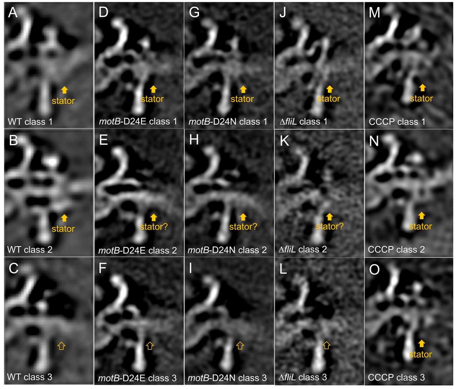
Measurement of stator occupancies in WT,motB-D24E,motB-D24N, ∆fliL, and CCCP treated WT motors.
After we got the subtomogram average structure of the WT,motB-D24E,motB-D24N, ∆fliL, and CCCP treated WT motors, the regions around the 16 stator units (or corresponding regions) were rotationally aligned. Then 3D classification was based on the stator complex density in the extracted particles. Typically, we get three different class averages: class average with stator complex density, class average without stator complex density and class average that we are not sure whether there are stator complexes or not. Finally, the stator occupancy was calculated by dividing the particle numbers in the class average with stator complex densities over the total particle numbers. Three selected class averages from the classification results of WT (A-C), motB-D24E (D-F), motB-D24N (G-I) and ∆fliL(J-L), and CCCP treated WT (M-O) motor structures are shown here. (A, B, D, G, J, M, N, O) show class averages with stator complexes. (C, F, I and L) show class averages without stator complexes. (E, H and K) show class averages that we are not certain whether there are stator complexes or not.
Figure 4—figure supplement 2
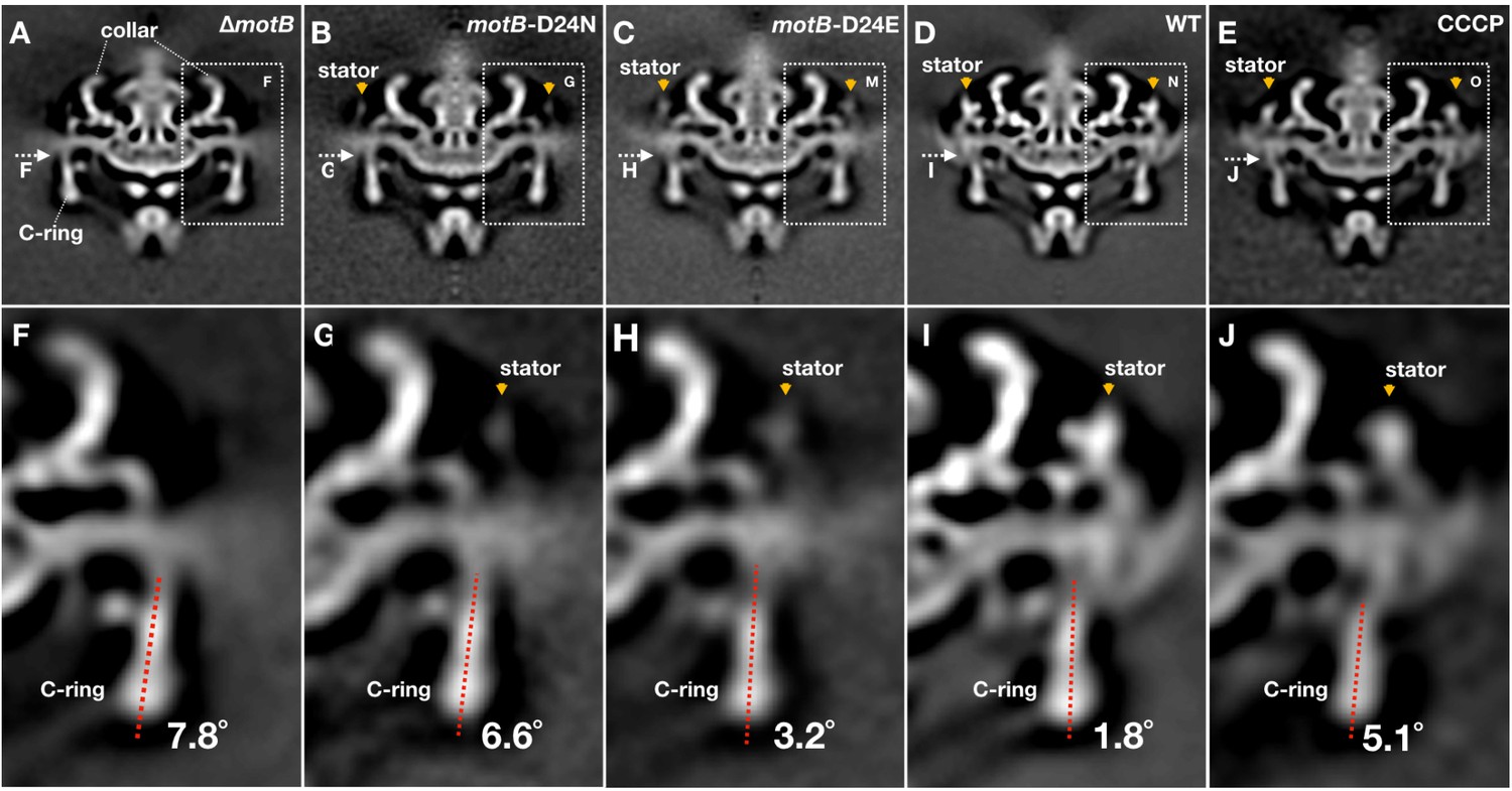
Conformational changes of the C-ring induced by stator-binding and proton flux.
(A-E) A central section of ∆motB,motB-D24N,motB-D24E, WT and CCCP treated WT motor structures (16-fold symmetry was applied), respectively. Stator complex is indicated by orange arrows. (F-J) A zoom-in view showing the tilt angles of the C-ring away from the rotation axis in the ∆motB,motB-D24N,motB-D24E, WT and CCCP treated WT motor structures, respectively.
Figure 4—figure supplement 3

Comparison of the motor structures from WT, ∆fliLand ∆motB.
(A-C) A central section of the WT, ∆fliLand and ∆motBmotor structures (16-fold symmetry was applied), respectively. Stators are indicated by orange arrows. (D-F) A cross-section at the top of the C-ring from the WT, ∆fliLand and ∆motBmotor structures, respectively. Stator complexes are indicated by orange arrows. Note that the stator densities in the ∆fliLmotor is relatively weak compared to those in the WT motor, suggesting that there are fewer stator units in the ∆fliLmotor.
Figure 4—figure supplement 4
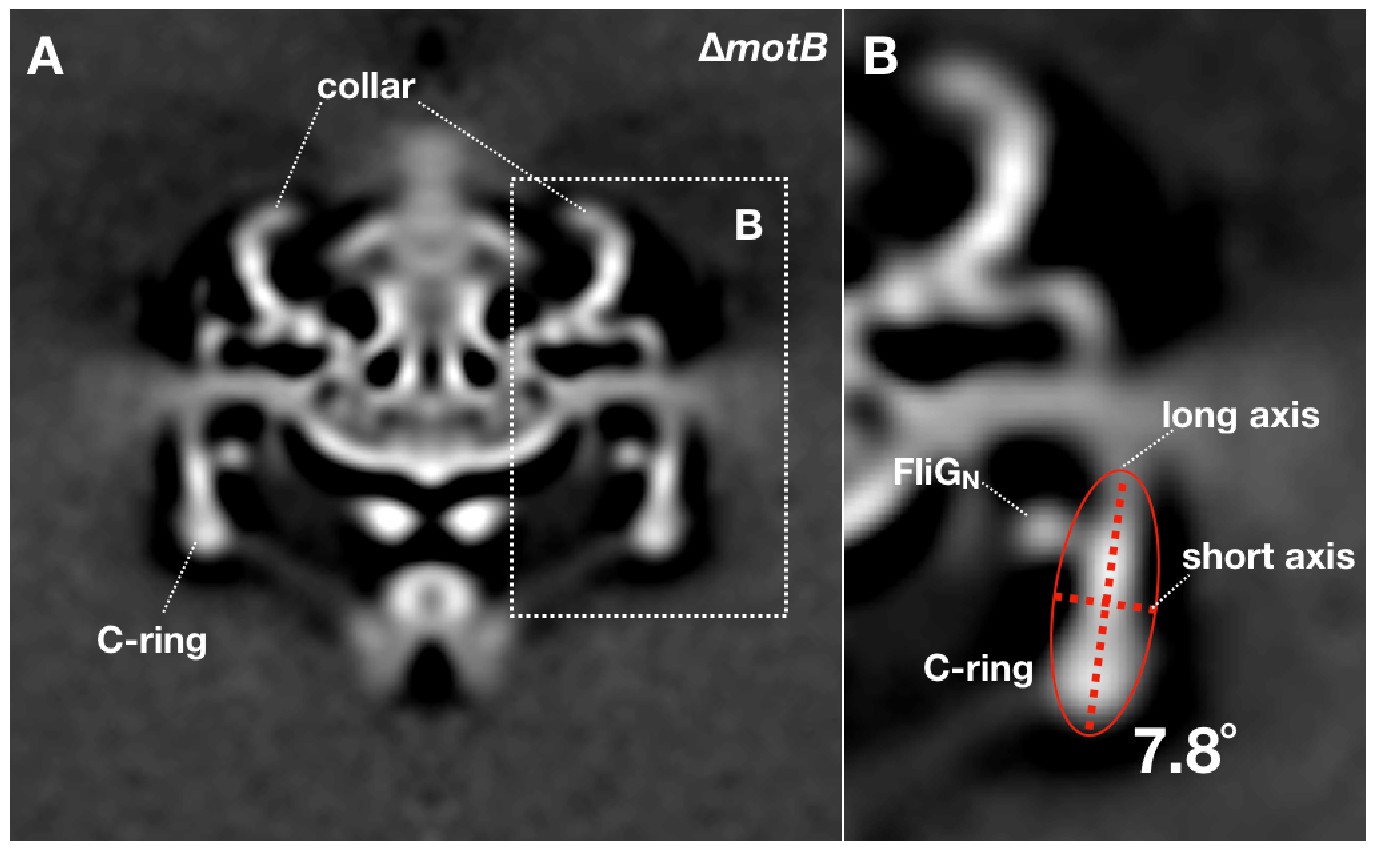
Measurement of the C-ring tilt angle in the ∆motBmotor structure.
16-fold symmetry was applied to the ∆motBmotor structure. (A) A cross section of the symmetrized ∆motBmotor structure. (B) Treat the C-ring density (ignore FliGNdensity) as a whole object, then calculate an ellipse that can fit the object shape. The angle between the long axis of the ellipse and the Y-axis was considered as the tilt angle of the C-ring (7.8°). The tilt angles of the C-ring inmotB-D24N,motB-D24E and WT motor structures were measured by the same method.
Figure 5
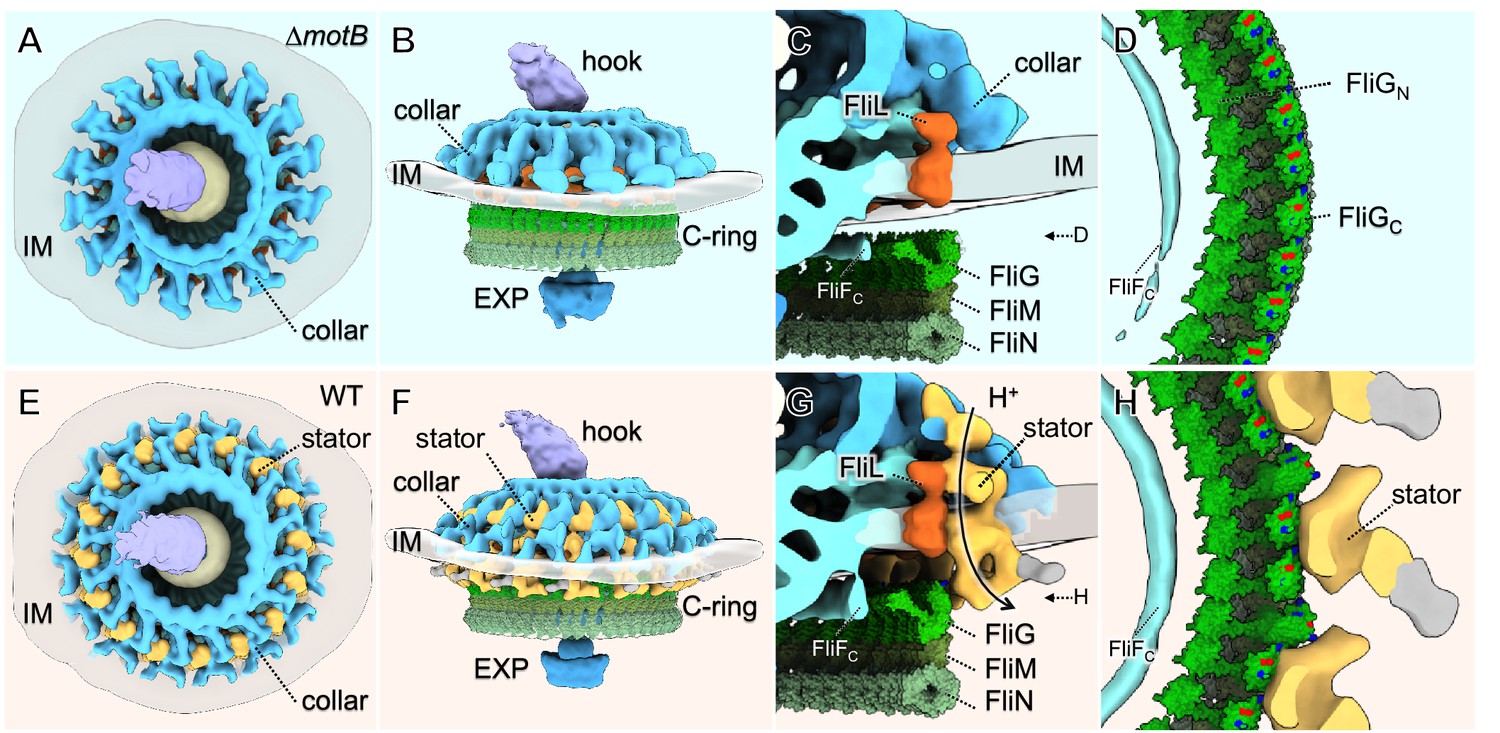
Molecular architecture of the stator-rotor interactions.
(A, B) A top and a side view showing the surface rendering of the ∆motBmotor, respectively. (C) A zoom-in view shows major flagellar components: the cytoplasmic domain of FliF (FliFC), FliL, FliG, FliM, FliN and the collar around the inner membrane (IM). (D) A top view of the interface between the C-ring and the MS-ring. FliFCof the MS-ring is adjacent to the FliGNof the C-ring. (E, F) A top and a side view showing the surface rendering of the WT motor. (G) A side view of the interface between the stator and the C-ring. The interaction powered by proton flux induces a conformational change of the C-ring, which appears to engage with the MS-ring through interactions between FliGNand FliFC. (H) A top view of the interface between the C-ring and the stators. The charged residues in FilGCare shown in blue (positive electrostatic potential) or red (negative electrostatic potential).
Figure 6

Schematic of stator assembly and stator-rotor interactions.
(A, B) Side and top views of stator assembly. A flagellar motor without stators is shown in the left panels. The WT motor with 16 fully assembled stators is shown in the right panels. Several key flagellar components are annotated: C-ring (green), export apparatus (EXP), collar (light blue) embedded in the inner membrane (IM), and hook. Two intermediates in stator assembly show partial occupancy of motors with blocked or attenuated proton conduction by the torque-generating units. (C) Top views of the C-rings from the motors shown in panels A and B. Without proton conduction (as shown in themotB-D24Nmutant), some stators (tan squares) interact with the FliG units (colored in dark green circles), yet there is relatively little conformational change in the C-ring. When protons flow through the stator channels, the torque generated by the stator induces conformational changes in the FliG units with which they are in contact (colored in light green). In themotB-D24E motor, fewer stator units are engaged, and they have a decreased proton flow. As a consequence, the deformations of the C-ring are not as large as in the WT motor, in which the 16 stator units assembled around the C-ring are rapidly conducting protons and generating torque. We propose that the increasing deformation of the C-ring observed with increasing number and activity of assembled stator complexes reflects conformational changes induced by the power strokes of the cytoplasmic MotA loops pushing against the FliGc domain.
Videos
Video 1
Conformational change of the C-ring from the ∆motB motor to the WT motor.
https://doi.org/10.7554/eLife.48979.007
Video 2
Visualization of the stator-rotor interactions in B. burgdorferi.
https://doi.org/10.7554/eLife.48979.016Additional files
-
Supplementary file 1
Strains used in this study.
- https://doi.org/10.7554/eLife.48979.018
-
Supplementary file 2
Cryo-ET data used in this study.
- https://doi.org/10.7554/eLife.48979.019
-
Transparent reporting form
- https://doi.org/10.7554/eLife.48979.020
Download links
A two-part list of links to download the article, or parts of the article, in various formats.
Downloads (link to download the article as PDF)
Open citations (links to open the citations from this article in various online reference manager services)
Cite this article (links to download the citations from this article in formats compatible with various reference manager tools)
Structural insights into flagellar stator–rotor interactions
eLife 8:e48979.
https://doi.org/10.7554/eLife.48979


