Receptor-based mechanism of relative sensing and cell memory in mammalian signaling networks
- Columbia University, United States
- Harvard Medical School, United States
- University of Florida, United States
Figures
Figure 1 with 4 supplements

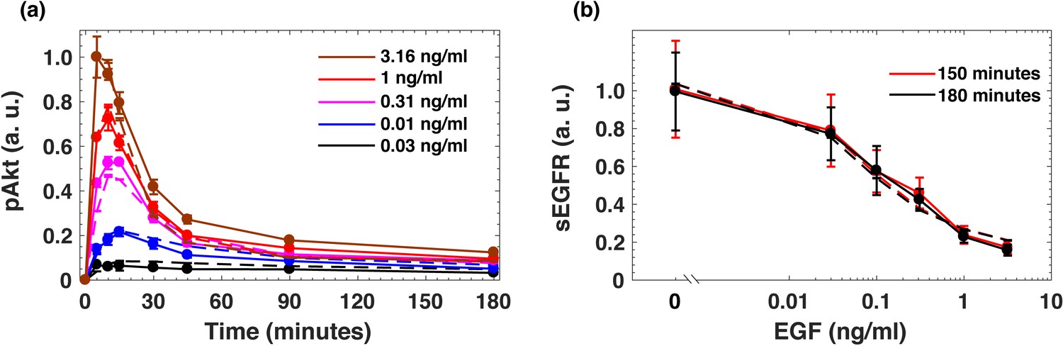
EGF-induced Akt phosphorylation and desensitization in MCF10A cells.
(a) Temporal profiles of phosphorylated Akt (pAkt) in cells exposed to increasing stimulation with extracellular EGF (see inset). (b) Maximal pAkt response as a function of EGF stimulation. (c) Steady state levels of surface EGFR (sEGFR) after 150 and 180 min of stimulation with a constant level of EGF. (d) Desensitization of the maximal pAkt response to an abrupt EGF stimulation. MCF10A cells were pre-treated with increasing background doses of EGF (x-axis) for three hours, followed by a second abrupt stimulation with the same concentration of EGF (2 ng/ml); the inset shows a schematic illustration of the experimental protocol. In all subpanels, error bars represent the standard deviation of n = 3 technical replicates. Source data: pakt_timecourses_first_step.mat and segfr_150_180mins.doseresponse.mat (available in Source code 1).
Figure 1—figure supplement 1
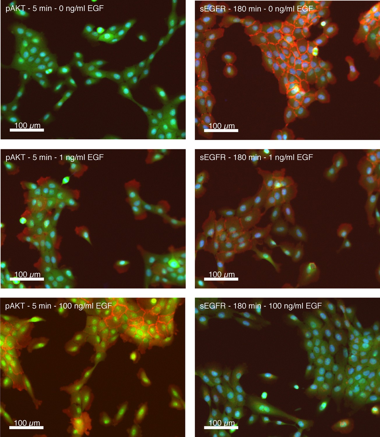
Representative immunofluorescence stains of Akt phosphorylation and cell surface EGF receptor levels.
Representative immunofluorescence images of MCF10A cells used for the generation of quantitative data on Akt phosphorylation (pAkt) and cell surface EGFR (sEGFR). (left) MCF10A cells 5 min after control treatment (a), or treatment with 1 ng/ml (b) or 100 ng/ml of EGF stained for pAKT. (right) MCF 10A cells 180 min after control treatment (a), or treatment with 1 ng/ml (b) or 100 ng/ml of EGF stained for sEGFR. Pseudocolors: blue: nuclei; green: cytoplasm; red: pAKT (left panels) or sEGFR (right panels).
Figure 1—figure supplement 2
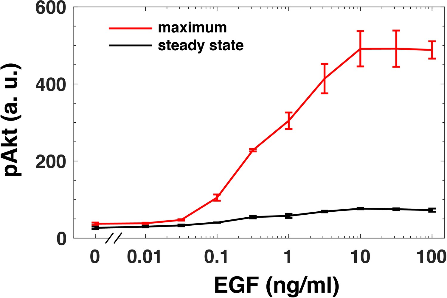
Adaptation of steady state pAkt response.
The maximal (red) and the steady state (black, 180 mins) pAkt response (y-axis) following a constant EGF stimulation (x-axis). The maximal and steady state responses were obtained from experimentally measured pAkt levels in MCF10A cells exposed to a constant EGF stimulation for 5, 10, 15, 30, 45, 90, and 180 min. Error bars represent the standard deviation of n = 3 technical replicates.
Figure 1—figure supplement 3
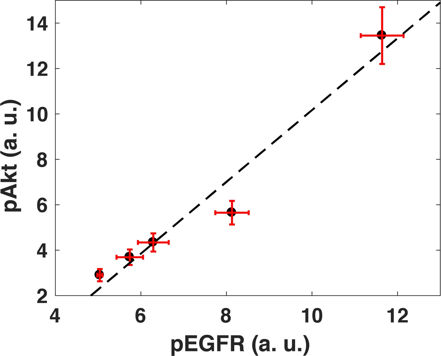
Akt phosphorylation response is linearly related to EGFR phosphorylation response.
Cells were treated with different doses of EGF for 5 min (0.1, 0.18, 0.32, 0.56, and 1 ng/ml) and phosphorylation levels of Akt and EGFR were then measured using quantiative Western blots (Pearson’s correlation coefficient is r2 = 0.95, regression p=0.004). Error bars on both axes represent the standard deviation of n = 3 technical replicates.
Figure 1—figure supplement 4
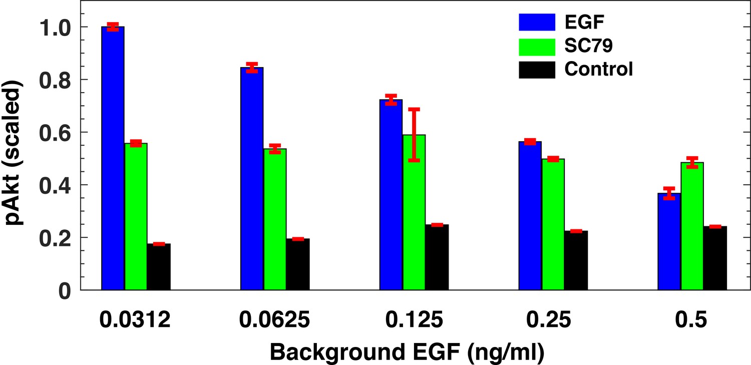
pAkt activation using pharmacological intervention.
pAkt levels after 180 min of exposure to different background EGF levels (x-axis) followed by stimulation with 2.5 ng/ml EGF for 5 min (blue) or with 20 μm SC79 for 30 min (green). The black bars represent pAkt levels after 180 min of stimulation with background EGF. Error bars represent the standard deviation of n = 3 technical replicates.
Figure 2 with 1 supplement

Computational model demonstrates the ability of the system to sense relative changes of EGF levels.
(a) Schematic of the computational model of the EGFR signaling cascade leading to phosphorylation of Akt. Rate constants marked with asterisks correspond to reactions associated with activated (phosphorylated) receptors. Only a subset of reactions in the network are shown for brevity. (b) In silico protocol used to explore relative sensing, showing the temporal profiles of EGF stimulation (top) and the corresponding profiles pAkt response (bottom). Cells were first exposed to various background EGF stimulations (blue and red) and were next subjected to the same abrupt fold change in EGF at time t0. The resulting maximal pAkt responses were similar for the same EGF fold change independent of background EGF stimulation, indicating relative sensing. (c) The maximal pAkt response observed after exposing the ODE model in silico to different background EGF levels (x axis), followed by a 2-, 3-, 4-, or 6- fold increase (different colors) in EGF; inset shows pAkt response over a wider range of background EGF levels. (d) Maximal pAkt responses (y axis) induced by stimulation with different EGF background levels (data points with the same shape and color) were combined and plotted as a function of the EGF fold change (x axis). Dashed line represents log-linear fit to data (Pearson’s r2 = 0.96, regression p value < 10−15). In all subpanels, error bars represent the standard deviation of n = 10 model fits. Source code: https://github.com/dixitpd/FoldChange/.
Figure 2—figure supplement 1
Dynamical model fits to experimental data.
(a) Average fits of dynamical model to the pAkt experimental data. (b) Average fits of dynamical model to the experimental surface EGFR dose response experimental data. In both panel a) and b), solid lines represent experimental data and the dashed lines represent the corresponding model fits. Error bars in data represent standard deviation between technical replicates. Error bars in model fits represent the standard deviation across the top 10 model fits.
Figure 3 with 6 supplements
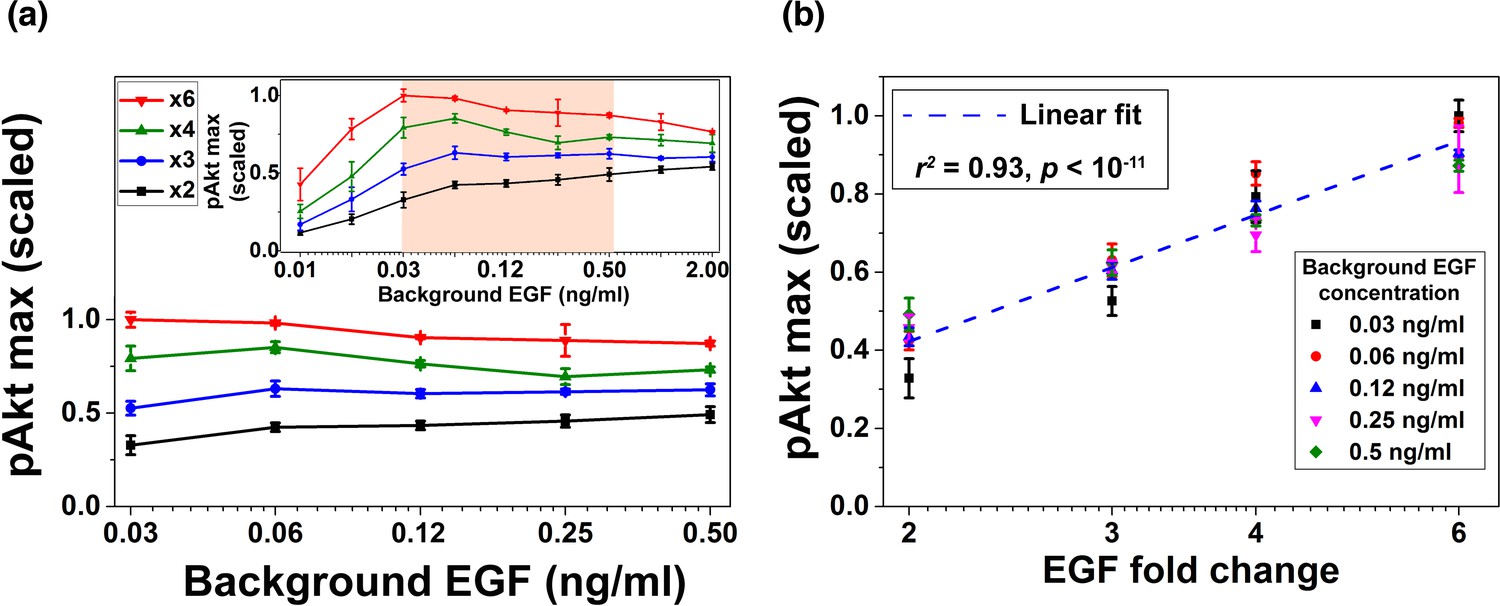
Experimental validation of EGF relative sensing by pAkt in MCF10A cells.
(a) The maximal pAkt responses after exposing cells to different background EGF levels (x axis) for 3 hr, followed by 2-, 3-, 4-, and 6-fold increases (different colors) in EGF. Inset shows experimental pAkt response over a wider range of background EGF levels. (b) Maximal pAkt responses (y axis) to fold changes in EGF depended approximately logarithmically on the fold change. Maximal pAkt responses induced by stimulation with various EGF background levels (data points with the same shape and color) were combined and plotted as a function of the EGF fold change (x axis). Dashed line represents log-linear fit to the data (Pearson’s r2 = 0.93, regression p value < 10−11). In all subpanels, error bars represent the standard deviation of n = 3 technical replicates. Source data: expt_data.mat (available in Source code 1).
Figure 3—figure supplement 1
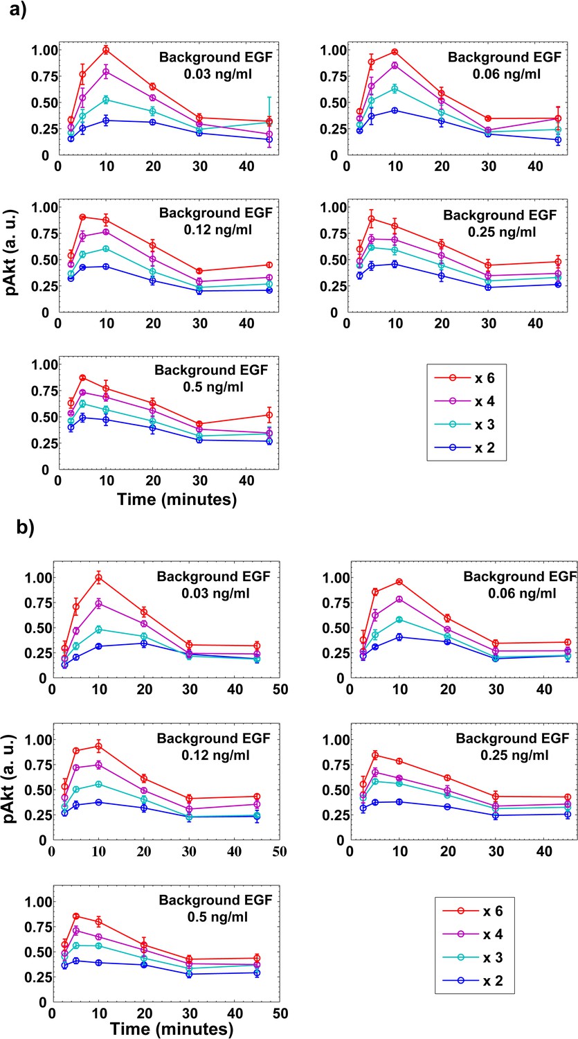
Dynamics of pAkt responses to step increases in EGF.
(a) MCF10A cells pretreated with a certain level of background EGF (shown in the top right corner of each figure) for three hours were then subjected to an abrupt step increases in EGF. (b) Biological replicate of panel a). Different colors represent different EGF folds changes. In both panels, individual data points represent averages from n = 3 technical replicates and error bars represent the corresponding standard deviation.
Figure 3—figure supplement 2
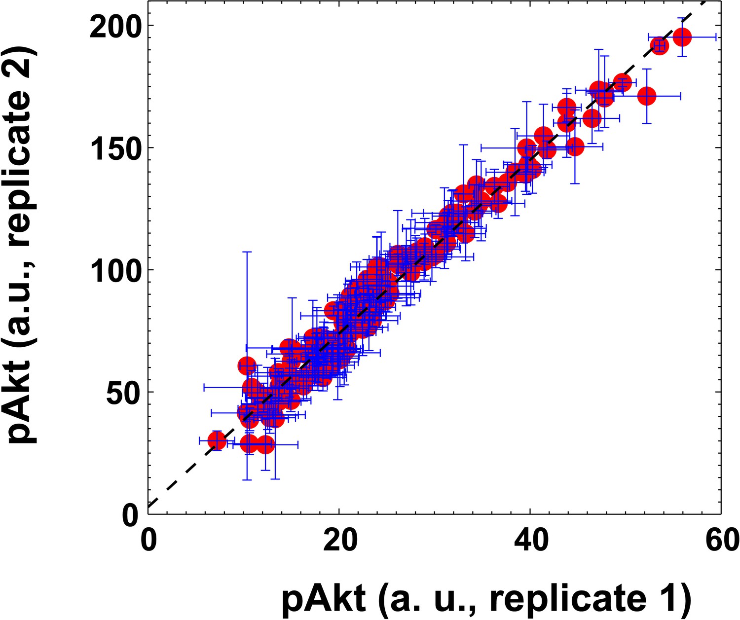
The scatter plot of pAkt levels observed in the two biological replicates shown in Figure 3—figure supplement 1.
Observed pAkt levels induced by EGF fold changes were highly reproducible between two biological replicates (Pearson’s correlation coefficient is r2 = 0.94, regression p<10−5). Error bars represent the standard deviation of n = 3 technical replicates.
Figure 3—figure supplement 3
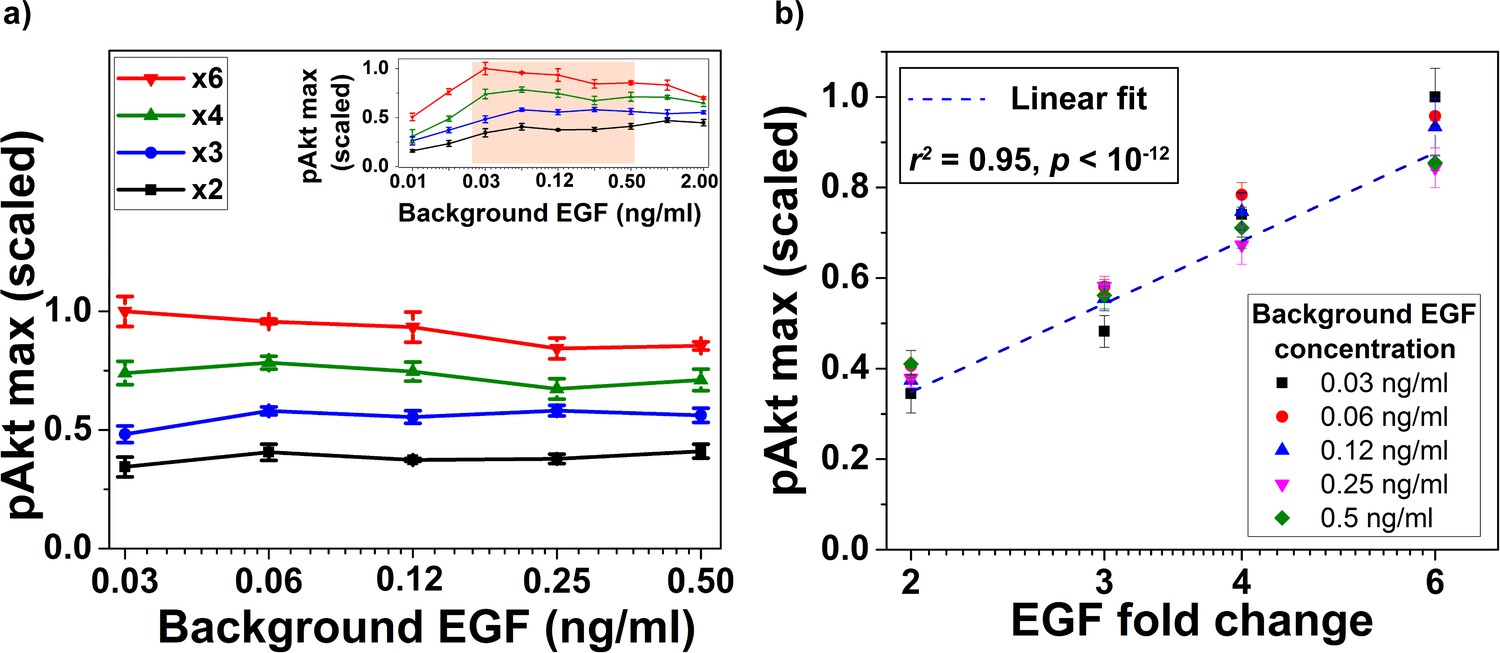
Biological replicate of the experiment demonstrating relative sensing of EGF by pAkt (main text Figure 3).
(a) The maximum of the measured pAkt response after exposing MCF10A cells to different background doses of EGF for 180 min followed by x2, x3, x4, or x6 fold change in background EGF exposure (shown on the logarithmic x-axis). Inset shows pAkt response over a wider range of background EGF exposures. (b) Maximum pAkt responses to fold changes in EGF depend log linearly on the fold change in EGF doses. Individual data series represent the same initial EGF concentration as shown in the legend. Dashed line represents log-linear fit to data (Pearson’s correlation coefficient is r2 = 0.95, regression p<10−12). Error bars represent the standard deviation of n = 3 technical replicates.
Figure 3—figure supplement 4
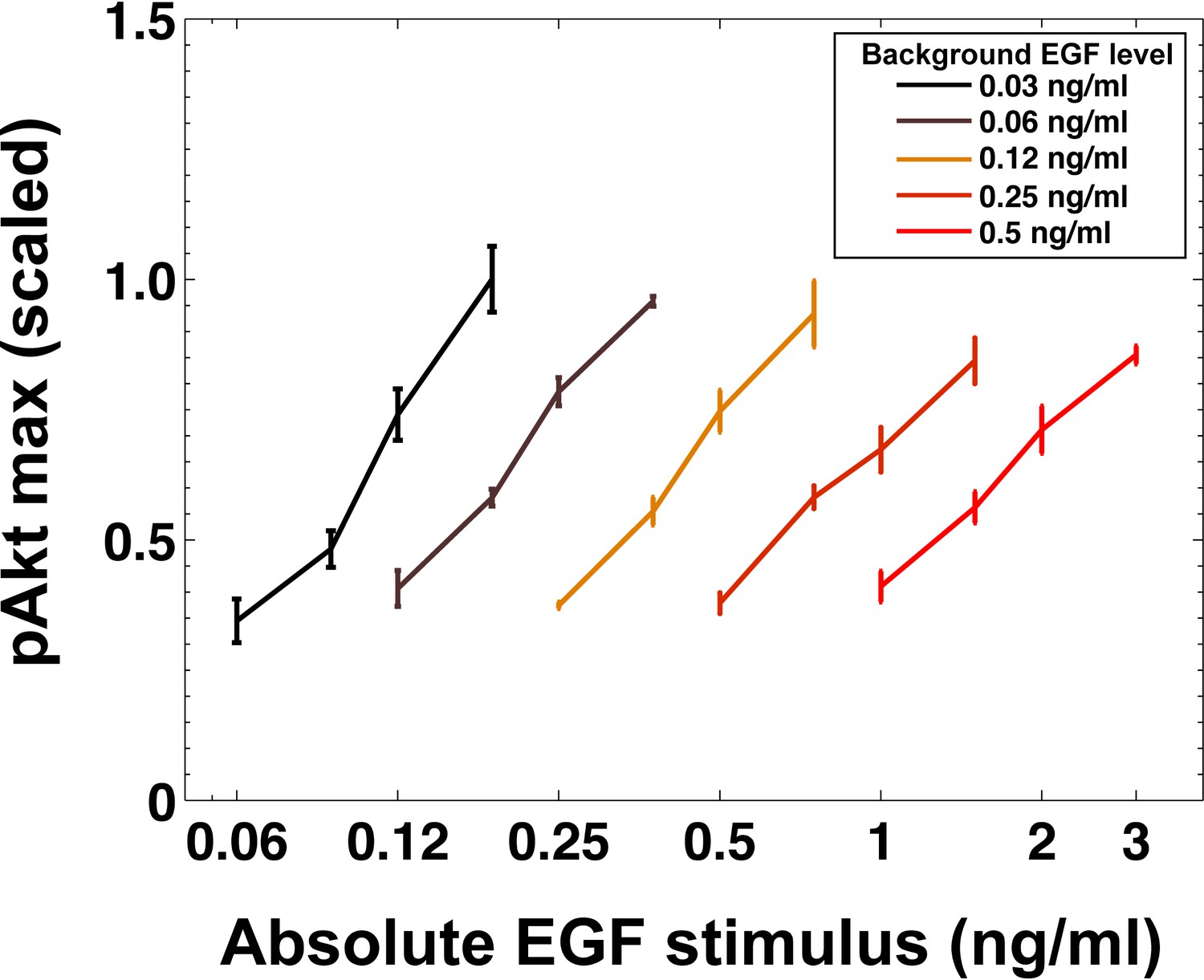
Maximal Akt phosphorylation response does not depend on the absolute EGF stimulus.
Maximal Akt phosphorylation response plotted as a function of absolute level of EGF abrupt signal across different levels of background EGF stimulation. Different colors indicate different background EGF levels. Error bars represent the standard deviation of n = 3 technical replicates.
Figure 3—figure supplement 5

Time-integral of pAkt response exhibits relative sensing of EGF.
(a) The time-integral of the measured pAkt response between 2.5 and 30 min after exposing MCF10A cells to different background doses of EGF for 180 min followed by x2, x3, x4, or x6 fold change in background EGF exposure (shown on the logarithmic x-axis). Inset shows pAkt response over a wider range of background EGF exposures. (b) Time-averaged pAkt response (between 2.5 to 30 min after a fold change in EGF) depends log linearly on the fold change. Individual data series represent the same initial EGF concentration as shown in the legend. Dashed line represents log-linear fit to data (Pearson’s correlation coefficient is r2 = 0.94, regression p<10−12). (c and d) are biological repeats of a) and b) (Pearson’s correlation coefficient is r2 = 0.94, regression p<10−12). (e and f) show similar plots for integrals computed on pAkt responses simulated in silico from top 10 best fit models (Pearson’s correlation coefficient is r2 = 0.92, regression p<10−10). Error bars represent the standard deviation of n = 3 technical replicates in subpanels a to d.
Figure 3—figure supplement 6
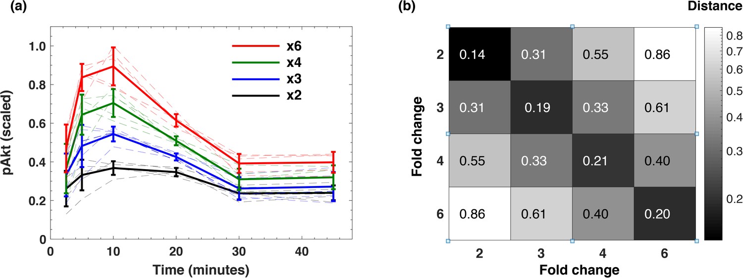
Dynamic time course of pAkt response exhibits relative sensing of EGF fold change.
(a) The dynamic pAkt response (bold lines) averaged over multiple background EGF levels corresponding to stimulation with the same EGF fold change. The faint time courses of the same color represent individual pAkt responses to the same EGF fold change at different background stimulation levels. Error bars represent the standard deviation across n = 5 background EGF doses for the same fold. (b) The averaged squared difference of pAkt response timecourses calculated between multiple background stimulation levels for the same EGF fold changes (diagonal), and for different EGF fold changes (off-diagonal).
Figure 4
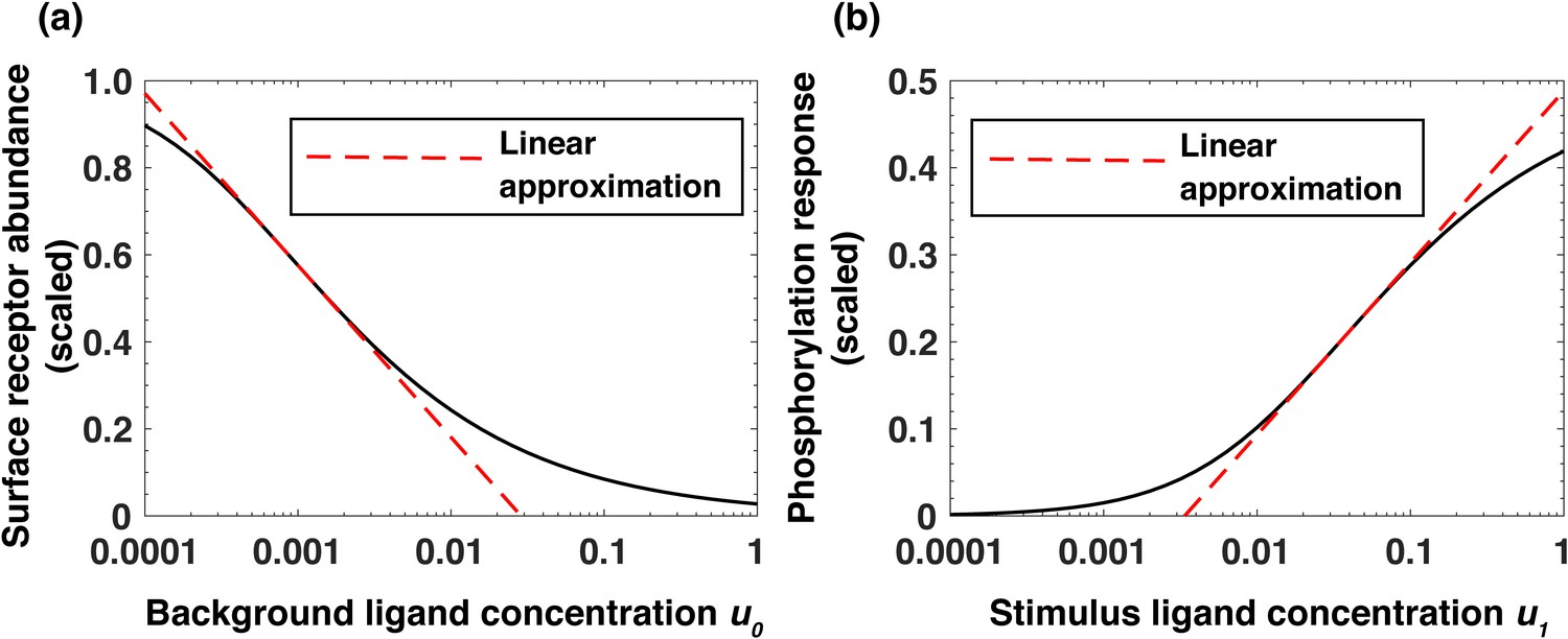
Analytical model of the system predicts log-linear relationships leading to receptor-based memory and relative sensing.
(a) Approximate log-linear dependence of the scaled steady-state surface receptor abundance on the normalized background ligand concentration , where is the equilibrium dissociation constant of EGF binding to EGFR. (b) Approximate log-linear dependence of the maximal phosphorylation response on the normalized ligand stimulus . Dashed red lines represent the exact log-linear approximation.
Figure 5
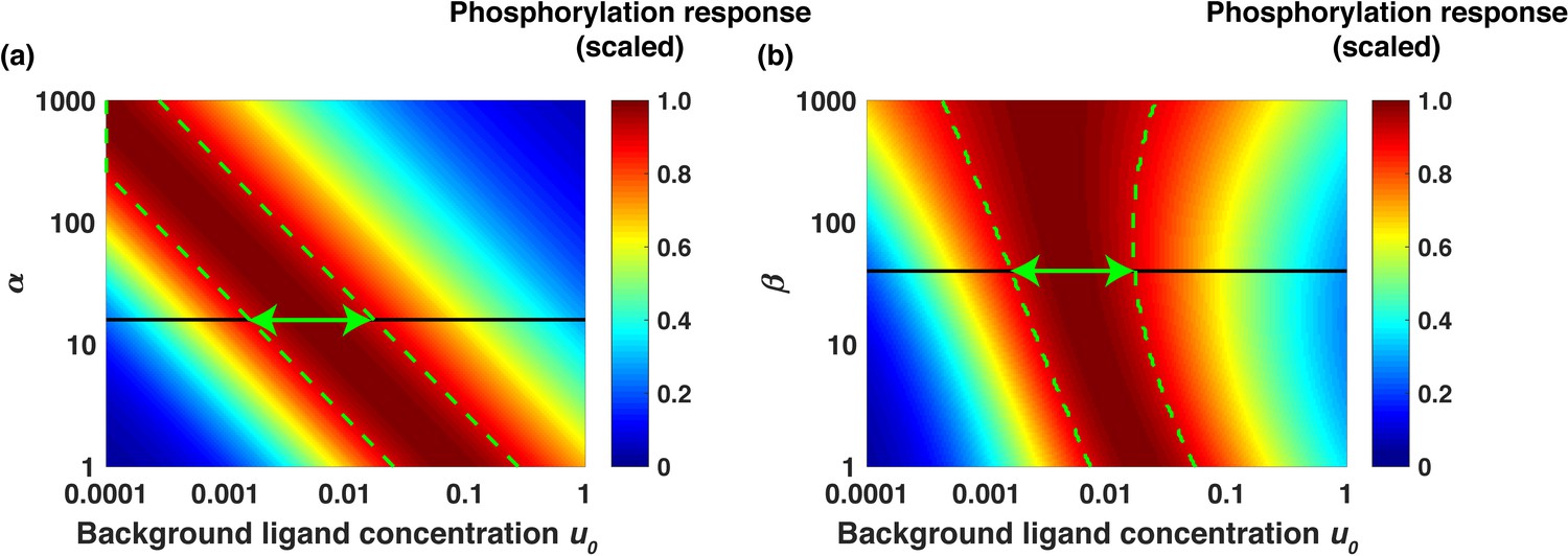
Analytical model predicts the range of approximate EGF relative sensing.
Scaled phosphorylation response to a six-fold change in extracellular EGF concentration as a function of the scaled background ligand concentration ( ). (a) The phosphorylation response as a function of background ligand concentration (x-axis) is shown for different values of the parameter α (y-axis), when the parameter β is fixed at β=40. (b) The phosphorylation response as a function of background ligand concentration (x-axis) is shown for different values of β (y-axis), when α is fixed at α=15. The colors represent the scaled phosphorylation response. The green dashed lines delineate the parameter ranges where the fold change detection is >90% accurate. The horizontal black lines correspond to the parameter values α=15 and β=40, which were estimated from experimental data fits; the horizontal green double arrows represent the predicted range of relative sensing for the investigated PI3K-Akt cascade.
Figure 6 with 2 supplements
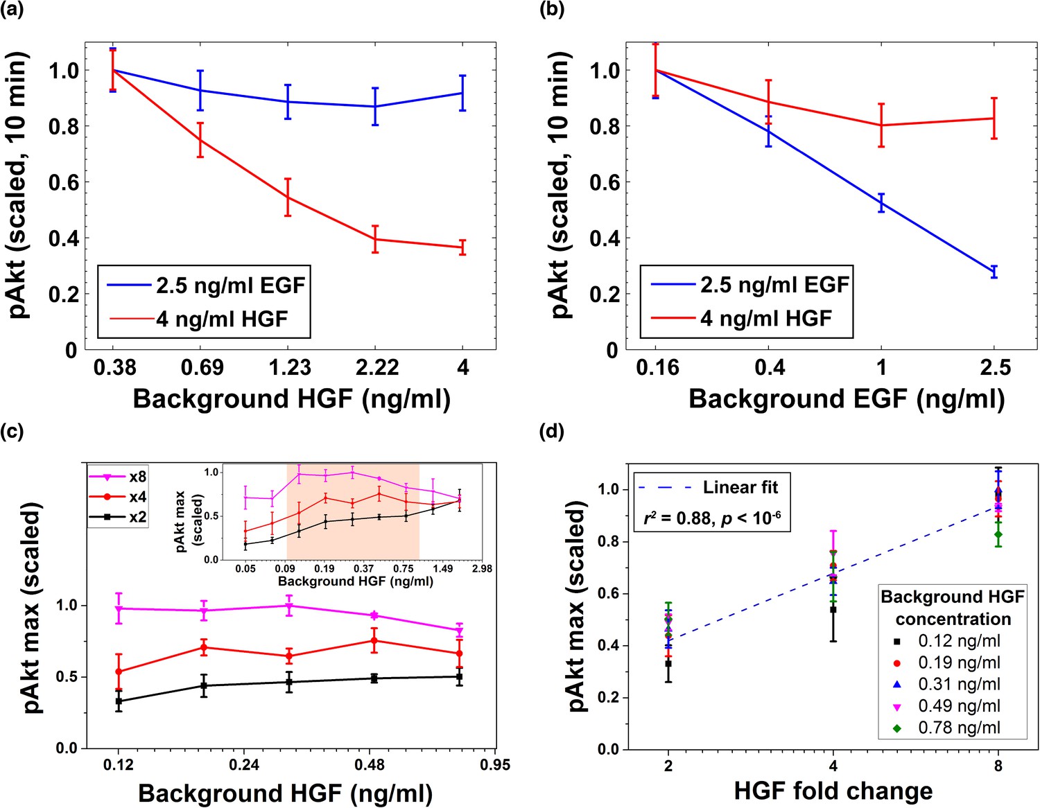
Desensitization and ligand-specific cell memory for EGF- and HGF-induced pAkt responses.
MCF10A cells were first exposed to various background concentrations of either HGF or EGF for three hours, and then abruptly stimulated using either the same or the other growth factor. pAkt levels were then measured 10 min after the addition of the second stimulus. (a) EGF- (blue, 2.5 ng/ml) or HGF- (red, 4 ng/ml) induced pAkt response in cells pre-exposed with various background concentrations of HGF (x axis). (b) EGF- (blue, 2.5 ng/ml) or HGF- (red, 4 ng/ml) induced pAkt response in cells pre-exposed with various background concentrations of EGF (x axis). (c) The maximal pAkt response in MCF10A cells exposed to different background doses of HGF (x axis) for 3 hr, followed by 2-, 4-, and 8-fold increase (different colors) of HGF. Inset shows experimental pAkt response over a wider range of background HGF levels. (d) The maximal pAkt responses (y axis) to HGF fold changes depended approximately logarithmically on the fold change (x axis). Maximal pAkt responses induced by stimulation with various HGF background levels (data points with the same shape and color) were combined and plotted as a function of the HGF fold change (x axis). Dashed line represents log-linear fit to data (Pearson’s r2 = 0.88, regression p value < 10−6). In all subpanels, error bars represent the standard deviation of n = 3 technical replicates. Source data: expt_data.mat (available in Source code 1).
Figure 6—figure supplement 1
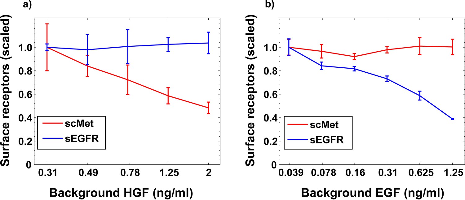
Stimulation with different growth factors leads to specific removal of cognate receptors from the cell surface.
(a) Experimentally measured surface EGFR and surface cMET dose responses in MCF10A cells treated with HGF for 3 hr. (b) Experimentally measured surface EGFR and surface cMET dose responses in MCF10A cells treated with EGF for 3 hr. Error bars represent the standard deviation of n = 3 technical replicates.
Figure 6—figure supplement 2
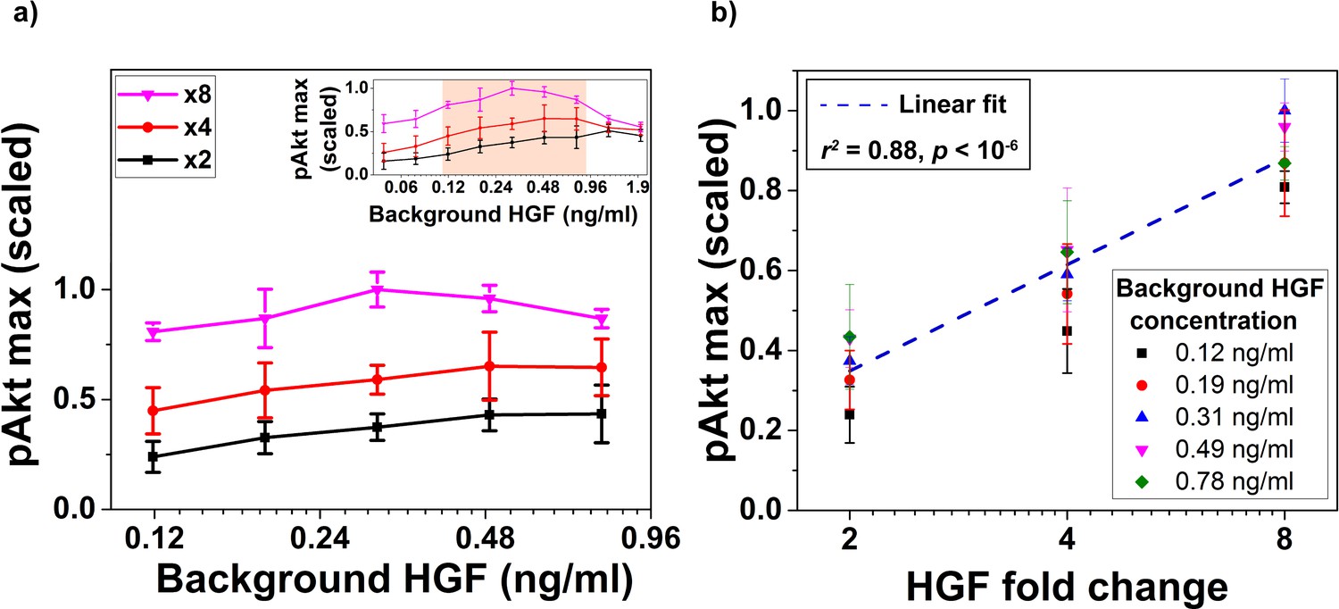
Biological replicate of the experiment demonstrating relative sensing of HGF by pAkt (main text Figure 6c,d).
(a) The maximal pAkt response (y-axis) after exposing MCF10A cells to different background doses of HGF (x-axis) for 3 hr followed by x2, x4, or x8 abrupt fold change in HGF stimulation. Inset shows pAkt response over a wider range of background HGF exposures. (b) Maximal pAkt response to fold changes in HGF depended approximately logarithmically on the HGF fold change. Individual data series corresponding to the same background HGF concentration are shown with the same color. Dashed line represents log-linear fit to data (Pearson’s correlation coefficient is r2 = 0.88, regression p<10−6). Error bars represent the standard deviation of n = 3 technical replicates.
Figure 7 with 1 supplement

Relative sensing of EGF concentrations by pAkt is propagated to FoxO3.
MCF10A cells were first exposed to two background concentrations of EGF for three hours, and then were stimulated with 3- and 6- fold increase in EGF concentrations. The ratio of nuclear-to-cytoplasmic FoxO3 levels (y-axis) was measured using quantitative immunofluorescence (Materials and methods) after 15 min of the EGF fold changes. Statistical significance was calculated using the Wilcoxon rank sum test (n = 5); * corresponds to p<0.01, and n. s. corresponds to p>0.1. Error bars represent the standard deviation of n = 5 technical replicates. Source data: expt_data.mat (available in Source code 1).
Figure 7—figure supplement 1

Biological replicate of the experiment showing relative sensing of EGF by FoxO3.
MCF10A cells were first exposed to two background concentrations of EGF for 3 hr, and then were stimulated with 3- and 6- fold increase in EGF concentration. The ratio of nuclear to cytoplasmic FoxO3 levels (y-axis), measured 15 min after the EGF fold changes, depended on the relative but not absolute change of EGF concentration. Statistical significance was calculated using the Wilcoxon rank sum test (n = 5); n. s. corresponds to p>0.1, and * corresponds to p<0.01. Error bars represent the standard deviation of n = 5 technical replicates.
Appendix 1—figure 1
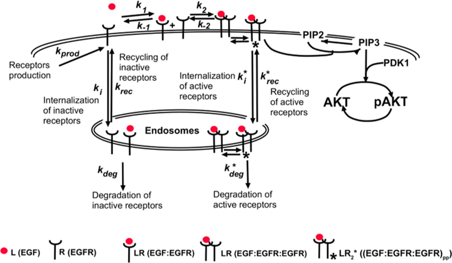
Model schematics of dimer-activated receptors signaling cascade.
Appendix 1—figure 2

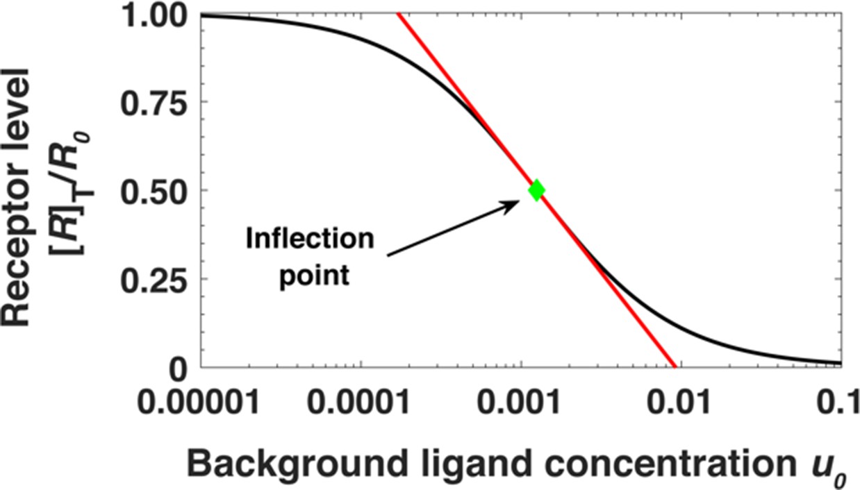
Steady state receptor levels decrease proportional to the logarithm of ligand concentration.
The steady state cell surface receptor level [R]T for receptors (black line) given by Equation (A22) depends approximately on the logarithm of the ligand concentration u0 = [L]0/Kd1 (red line, Equations A24). The inflection point is indicated by a green dot.
Appendix 1—figure 3
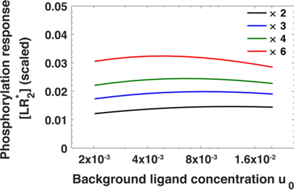
The maximum of the EGFR phosphorylation response [LR*2] as a function of ligand concentration u0 before step change in ligand concentration for fold changes u1/u0 in ligand concentration ranging from u1/u0 = 2 (black) to u1/u0 = 6 (red).
The phosphorylation response is estimated using Equation A30.
Appendix 1—figure 4
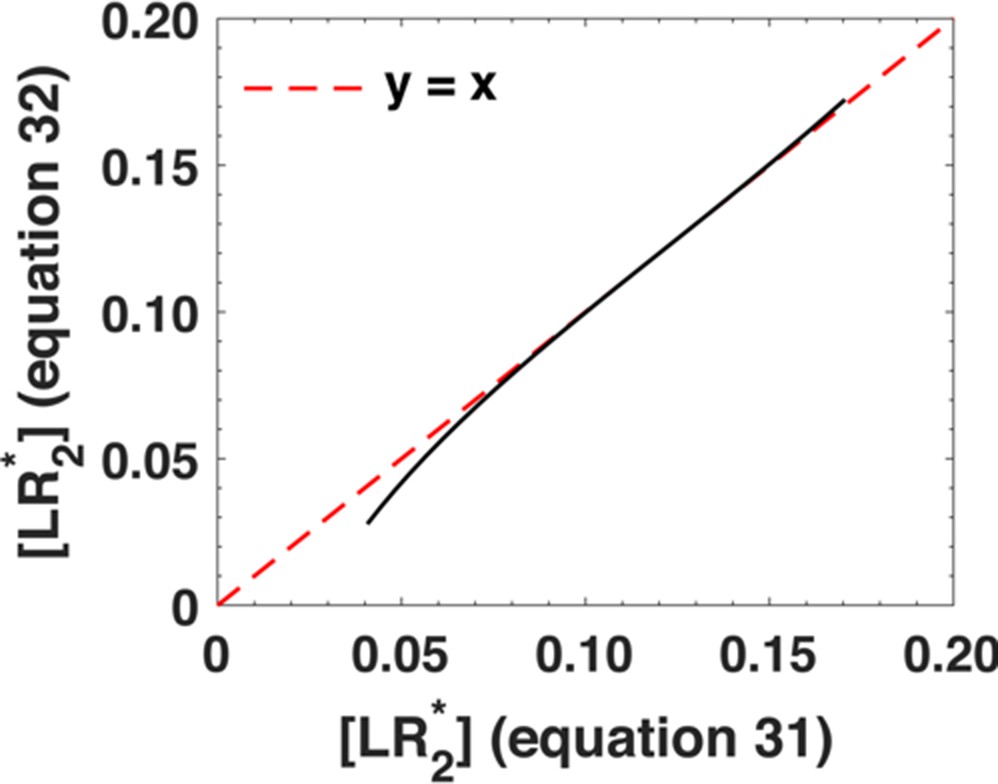
Comparison between the phosphorylation response as predicted by Equation A30 (x-axis) and its approximation, Equation A31 (y-axis).
We varied the ligand concentration u1 between u1 = 10−2-10-0.75. The black dots represent individual data points and the dashed red line represents x = y line.
Appendix 1—figure 5

Dimensionless parameters α and β dictate the range of relative sensing phenomenon.
(a) Scaled phosphorylation response [LR*2] as a function of background ligand concentration u0 = [L]0/Kd1 for different values of α and fold change u1/u0 = 6 when β was fixed to β = 40. The colors represent scaled phosphorylation response. The dashed green lines sketch the range of concentrations u0where [LR*2] is insensitive to the initial ligand concentration u0. (b) Scaled [LR*2] as a function of u0 for different values of β and fold change u1/u0 = 6 when α was fixed to α = 16. The dashed green lines sketch the range of concentrations u0 where phosphorylation response [LR*2] is insensitive to the background ligand levels. The green arrows show the range of background ligand concentrations over which relative sensing holds for the values of α and β evaluated from the model fits to the data.
Appendix 1—figure 6
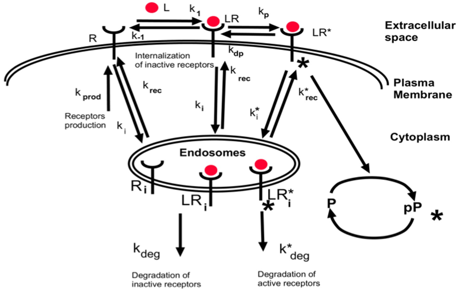
Simplified schematics of the steady state analytical model of monomer-activated receptor signaling.
Appendix 1—figure 7
Steady state receptor levels decrease proportional to the logarithm of ligand concentration.
The steady state cell surface receptor level [R]T for monomeric receptors (black line) given by Equation A45 depends approximately on the logarithm of the ligand concentration u0 = [L]0/Kd (red line). The green point represents the inflection point.
Appendix 1—figure 8

Monomeric receptors exhibit relative sensing.
The maximum of the phosphorylated receptors level [LR*] as a function of background ligand concentration [L]0 for fold changes [L]1/[L]0 in ligand concentration ranging from [L]1/[L]0 = 2 to [L]1/[L]0 = 6.
Appendix 1—figure 9

Dimensionless parameters κ and β dictate the range of relative sensing.
(a) Scaled response [LR*] as a function of u0 = [L]0/Kd for different values of κ and fold change [L]1/[L]0 = 2 when β was fixed at β = 40. The colors represent scaled phosphorylation response. The green lines sketch the range of concentrations [L]0 where [LR*] is insensitive to the initial ligand concentration [L]0. (b) Scaled [LR*] as a function of [L]0 for different values of β and fold change [L]1/[L]0 = 2 when κ was fixed at κ = 20. The green lines sketch the range of concentrations [L]0 where [LR*] is insensitive to the initial ligand concentration [L]0. The green arrows show the range of background ligand concentrations over which relative sensing holds for the values of κ and β estimated based on the model fits to the data.
Additional files
-
Source code 1
Immunofluorescence data and source code for fitting the ODE model to the data and further simulations.
- https://cdn.elifesciences.org/articles/50342/elife-50342-code1-v2.zip
-
Supplementary file 1
Table of ODE model parameter ranges.
Descriptions and literature-based estimates of rate parameters and species abundances.
- https://cdn.elifesciences.org/articles/50342/elife-50342-supp1-v2.xlsx
-
Supplementary file 2
Description of chemical species in the ODE model.
- https://cdn.elifesciences.org/articles/50342/elife-50342-supp2-v2.xlsx
-
Supplementary file 3
Description of chemical reactions in the ODE model.
- https://cdn.elifesciences.org/articles/50342/elife-50342-supp3-v2.xlsx
-
Transparent reporting form
- https://cdn.elifesciences.org/articles/50342/elife-50342-transrepform-v2.docx
Download links
A two-part list of links to download the article, or parts of the article, in various formats.
Downloads (link to download the article as PDF)
Open citations (links to open the citations from this article in various online reference manager services)
Cite this article (links to download the citations from this article in formats compatible with various reference manager tools)
Receptor-based mechanism of relative sensing and cell memory in mammalian signaling networks
eLife 9:e50342.
https://doi.org/10.7554/eLife.50342


