The giant mimivirus 1.2 Mb genome is elegantly organized into a 30-nm diameter helical protein shield
- Aix–Marseille University, Centre National de la Recherche Scientifique, Information Génomique & Structurale, Unité Mixte de Recherche 7256 (Institut de Microbiologie de la Méditerranée, FR3479, IM2B), France
- Univ. Grenoble Alpes, CNRS, CEA, Institut de Biologie Structurale (IBS), France
- Centre for Structural Systems Biology, Leibniz Institute for Experimental Virology (HPI), University of Hamburg, Germany
- Division of Structural Biology, Wellcome Centre for Human Genetics, University of Oxford, United Kingdom
- Univ. Grenoble Alpes, CEA, INSERM, IRIG, BGE, France
Figures
Figure 1 with 10 supplements

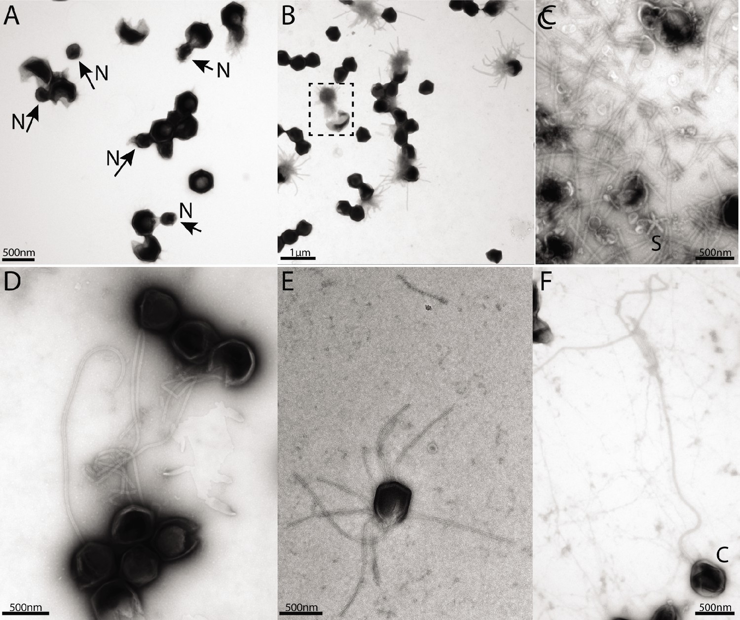
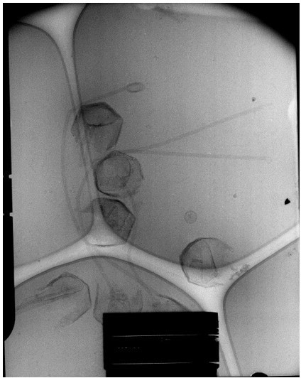
The mimivirus genomic fiber.
(A) Micrograph of an ultrathin section of resin-embedded infected cells showing the DNA tightly packed inside mimivirus capsids (C) with electron dense material inside the nucleoid (N). The string-like features, most likely enhanced by the dehydration caused by the fixation and embedding protocol, correspond to the genomic fiber (F) packed into the nucleoid. (B) Micrograph of negative stained mimivirus capsid (C) opened in vitro with the genomic fiber (F) still being encased into the membrane-limited nucleoid (N). (C) Multiple strands of the flexible genomic fiber (F) are released from the capsid (C) upon proteolytic treatment. (D) Micrograph of negative stained purified mimivirus genomic fibers showing two conformations the right fiber resembling the one in (B) and free DNA strands (white arrowheads). (E) Slices through two electron cryo tomograms of the isolated helical protein shell of the purified genomic fibers in compact (top) or relaxed conformation (bottom) in the process of losing one protein strand (Figure 1—figure supplement 2, Figure 1—videos 1, 4). (F) Different slices through the two tomograms shown in (E) reveal DNA strands lining the helical protein shell of the purified genomic fibers in compact (top) or relaxed conformation (bottom). Examples of DNA strands extending out at the breaking points of the genomic fiber are marked by black arrowheads. Note in the top panel, individual DNA strands coated by proteins (red arc). The slicing planes at which the mimivirus genomic fibers were viewed are indicated on diagrams on the top right corner as blue dashed lines and the internal colored segments correspond to DNA strands lining the protein shell. The thickness of the tomographic slices is 1.1 nm and the distance between tomographic slices in panels (E) and (F) is 4.4 nm. Scale bars as indicated.
Figure 1—figure supplement 1
Negative staining micrographs of opened mimivirus reunion virions before purification of the genomic fiber.
(A) Spherical nucleoids (N) released from the capsids upon specific treatment (see methods). (B) Dissolved nucleoids expelled from the opened capsids after regular treatment (the region marked with dashed lines is enlarged in Figure 1C), all of the opened capsids (>25%) are releasing the condensed genomic fiber. (C) Multiple broken genomic fibers can be seen next to debris prior to purification and an isolated Stargate (S). (D, E) Multiple segments of the flexible genomic fiber are released upon proteolytic treatment of the capsids. (F) Example of a long, flexible, genomic fiber released from an open capsid (C).
Figure 1—figure supplement 2
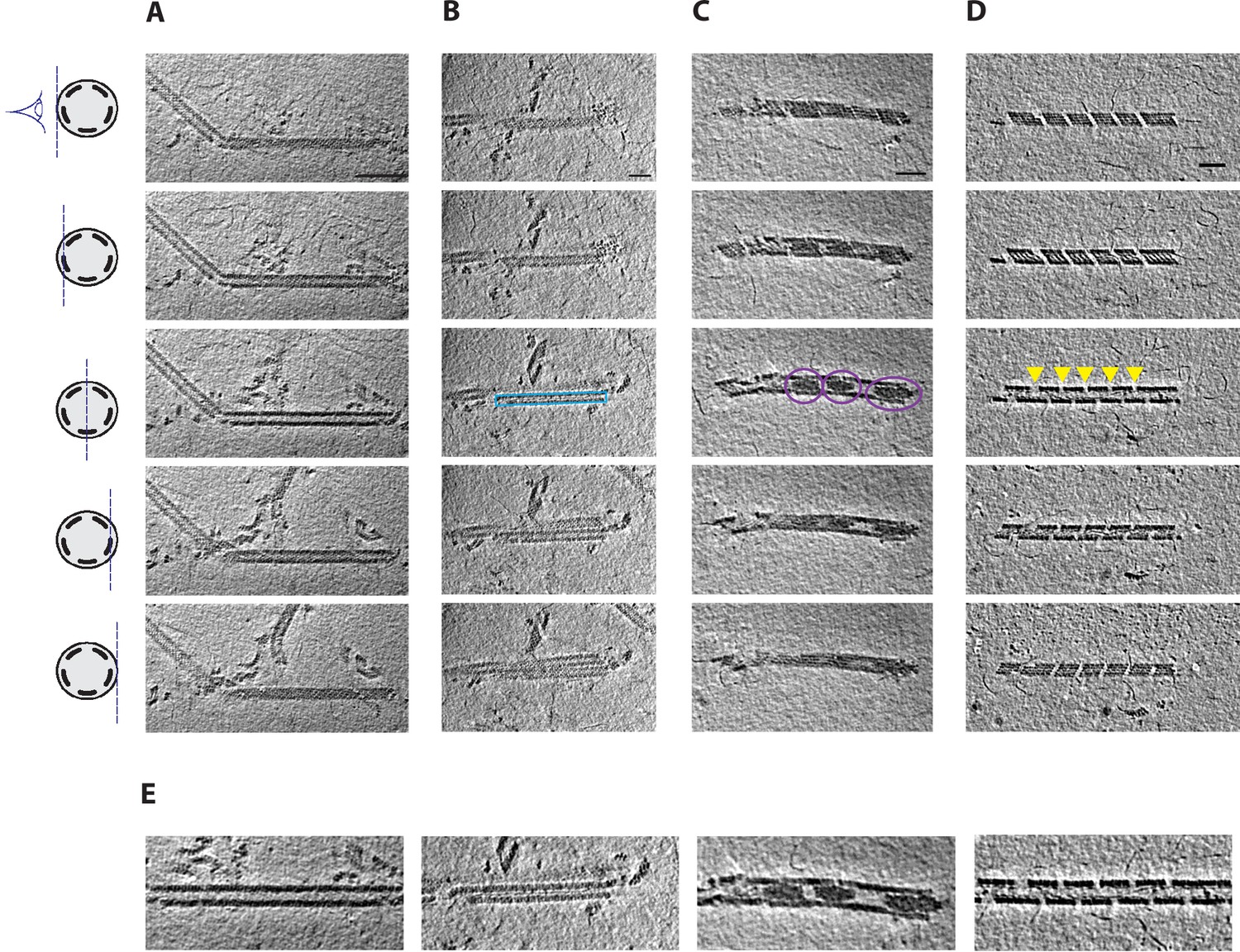
Cryo-electron tomography (cryo-ET) of mimivirus genomic fiber.
(Upper panel) Slices through tomograms exhibiting different features of compact, unwinding, and broken genomic fibers of mimivirus. (A) Slices through a cryo-tomogram focused on a long and broken fiber. Features of the protein shell are visible in tangential slices (top and bottom), while filamentous densities corresponding to DNA strands become visible when slicing deeper inside the fiber. Scale bar, 100 nm. (B) A straight filament running along the fiber symmetry axis has been observed in several cases (blue rectangle), which may correspond to a single or a bundle of DNA strands dissociated from the protein shell. (C) Large amorphous electron dense structures have been observed inside the lumen of the fiber (highlighted with purple circles). (D) DNA strands are often observed emanating from breaks along the genomic fiber, partially disassembling (indicated with yellow arrowheads). (E) Detail of the central slices through the genomic fibers showed in the third depicted slice in A–D. Thickness of the slices is 1.1 nm. Distance between the tomographic slices (from top to bottom) is 4.4 nm between the first and second and the fourth and fifth, and 6.6 nm between the third and second or fourth. The scheme on the left represents a cross-section of a cartoon representation of the 5-start genomic fiber depicted as a cylinder containing five strands of colored DNA internally lining the helical protein shell. It also indicates the plane through which the genomic fiber is viewed as 2D slices extracted from the tomograms in Figure 1—video 1 (A), Figure 1—video 2 (B), Figure 1—video 3 (C), and Figure 1—video 4 (D). Scale bars (B–D), 50 nm.
Figure 1—figure supplement 3
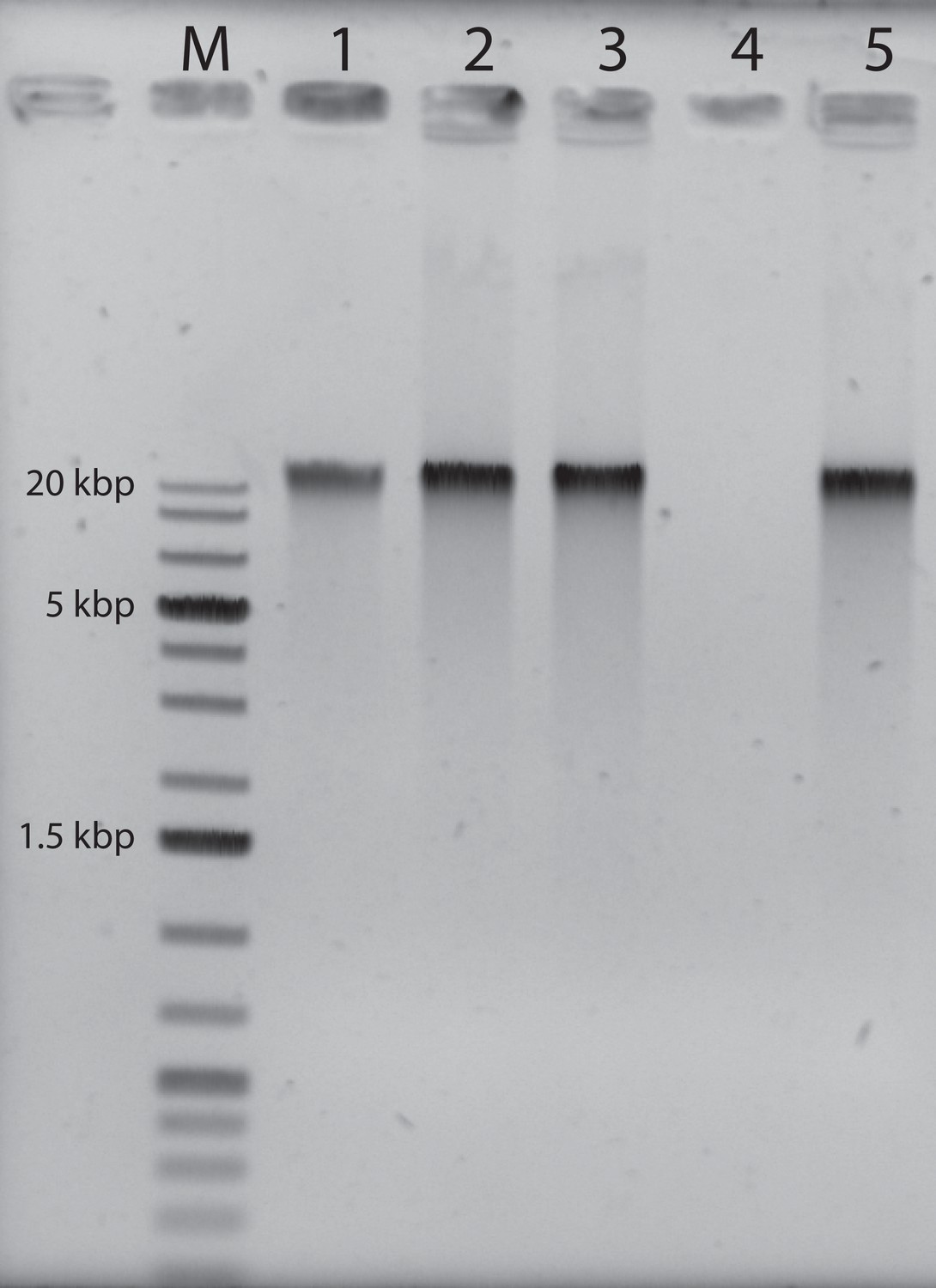
Agarose gel electrophoresis of the purified genomic fiber compared to the viral genomic DNA: M: molecular weight markers (1 kbp DNA Ladder Plus, Euromedex).
Lane 1, 100 ng of mimivirus genomic DNA, Lane 2: 200 ng of untreated genomic fiber, Lane 3: 200 ng of proteinase K (PK)-treated genomic fiber, Lane 4: 200 ng of DNase- and PK-treated genomic fiber, Lane 5: 200 ng of RNase- and PK-treated genomic fiber.
-
Figure 1—figure supplement 3—source data 1
Source data of the agarose gel.
- https://cdn.elifesciences.org/articles/77607/elife-77607-fig1-figsupp3-data1-v3.zip
-
Figure 1—figure supplement 3—source data 2
Source data of the agarose gel.
- https://cdn.elifesciences.org/articles/77607/elife-77607-fig1-figsupp3-data2-v3.zip
Figure 1—figure supplement 4
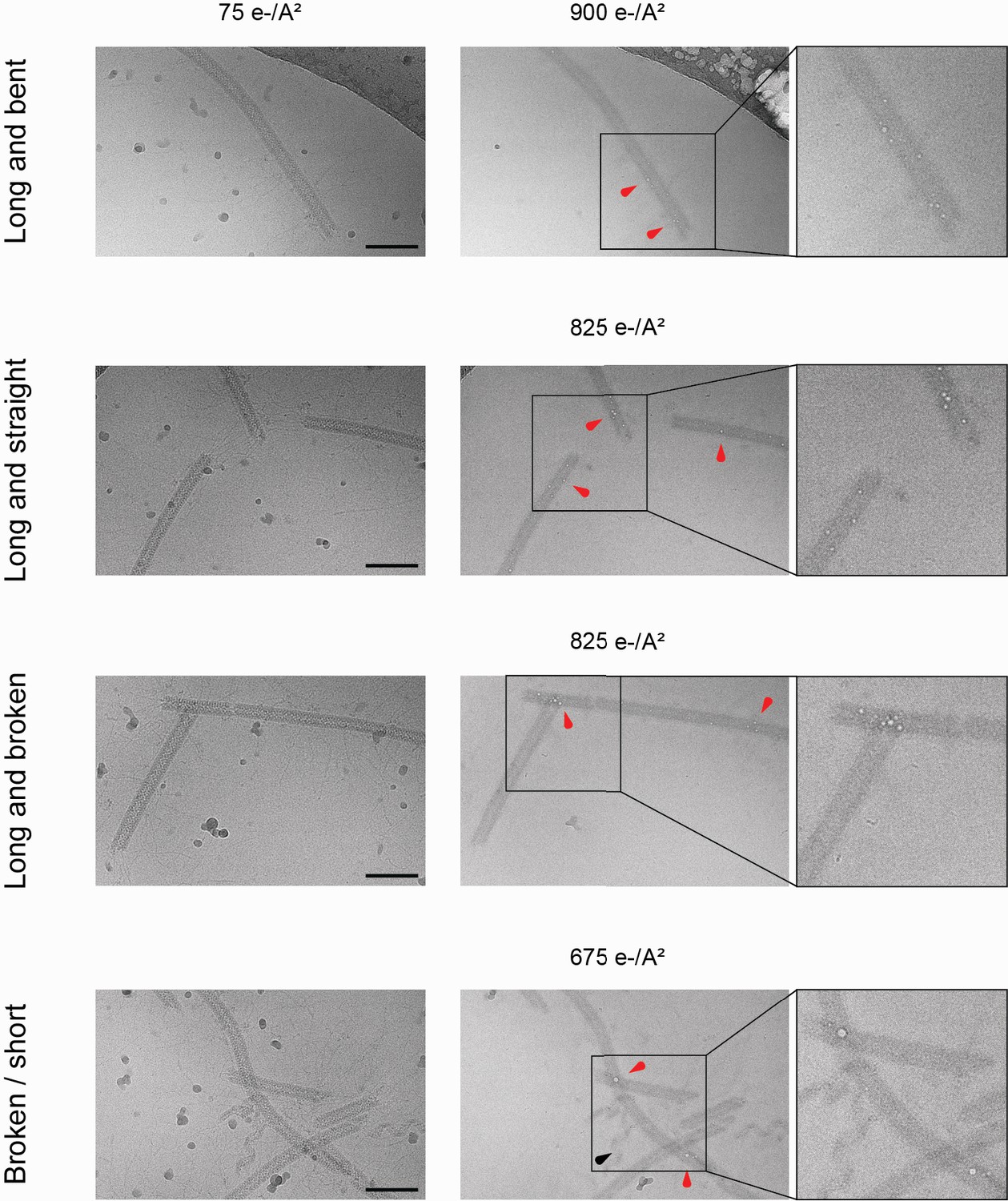
Bubblegrams on the mimivirus genomic fiber.
Field of view for genomic fibers either (from top to bottom): long and bent, long and straight, long and broken, or a mix of short and broken, subjected to a dose series. The total electron flux applied is specified for each field of view. First column: fibers showed after the first exposure of 75 e−/Å2. Second column: representative micrographs indicating the point at which the first sign of radiation damage as ‘bubbles’ inside the fiber (red arrowheads) were detected. Nucleoproteins with high nucleic acid content are often more susceptible to bubbling than pure proteinaceous structures. In unfolded ribbons (black arrowhead), no bubbles are detected at an accumulated flux of up to 1125 e−/Å2. Scale bars, 100 nm. Third column: enlarged view where the effect of radiation damage as trapped ‘bubbles’ is more clearly visible.
Figure 1—figure supplement 5
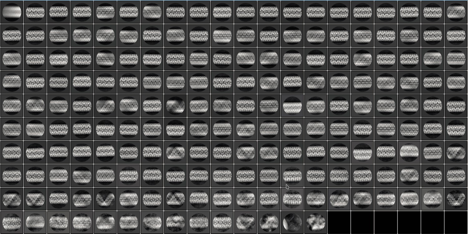
200 2D classes (6 empty) were obtained after reference-free 2D classification of fibers acquired (see methods) for single-particle analysis and extracted with a box size of 500 pixels in Relion 3.1.0 after motion correction, CTF estimation, and manual picking.
The 2D classes are representative of the different relaxation states of the mimivirus genomic fiber observed in our highly heterogeneous dataset.
Figure 1—figure supplement 6
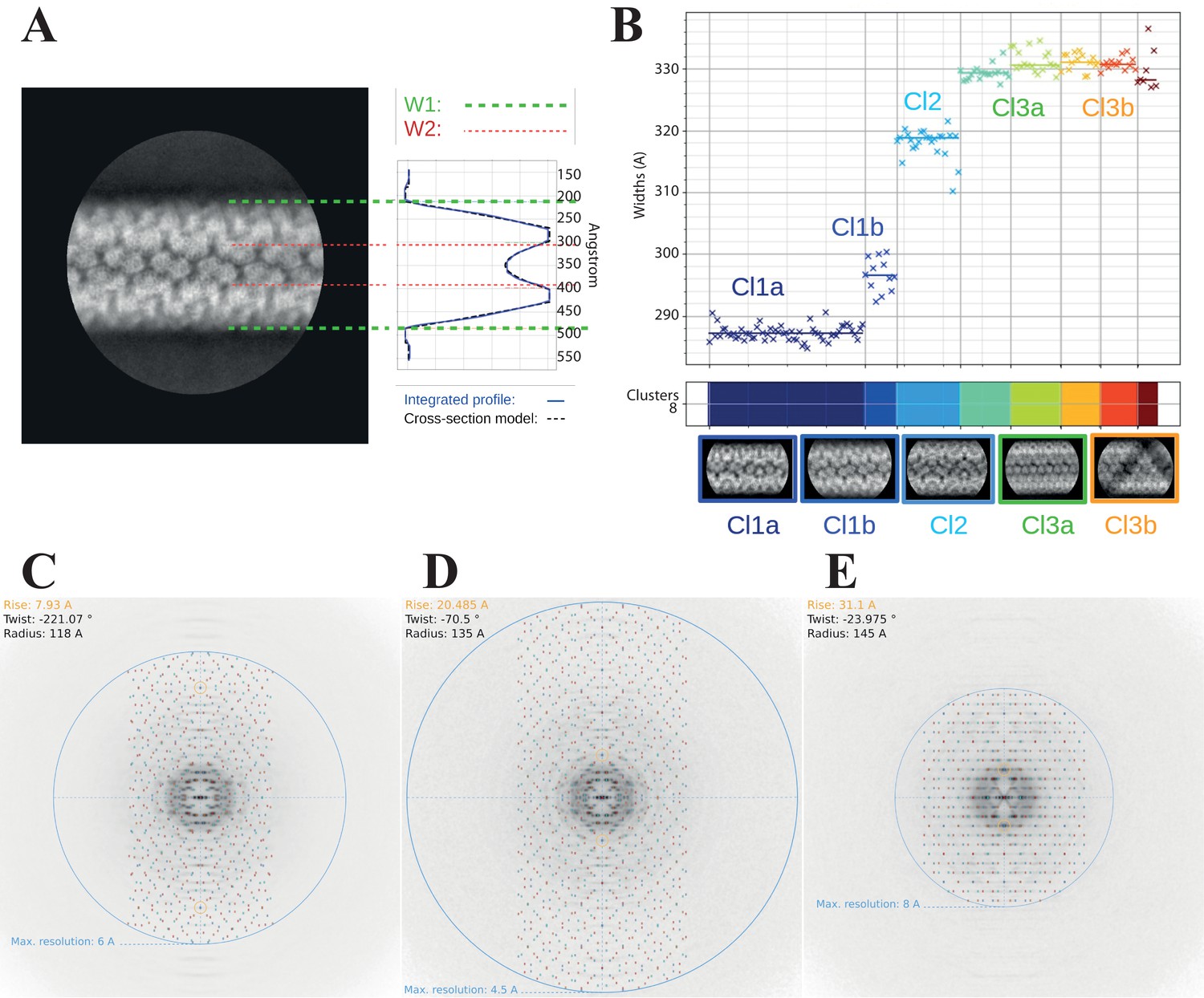
Clustering analysis of the 2D classes.
(A) Cross-section model adjusted to one 2D class, representative of cluster Cl1b, to estimate the parameters of the widths W1 (external) and W2 (internal). (B) Automatic sorting of the 2D classes using the fiber width W1 and pairwise correlations of the 2D classes resulting in three main clusters (compact, Cl1 in dark blue; intermediate, Cl2 in cyan and relaxed, Cl3 in green and orange). Power spectra indexing with Helixplorer (http://rico.ibs.fr/helixplorer/) for the candidate helical parameters estimation. (C) Cl1a: 5-start, cyclic symmetry C1 (https://tinyurl.com/mrxnyjwn), (D) Cl2: 6-start, cyclic symmetry C3 (https://tinyurl.com/yckmk79b), and (E) Cl3a: 5-start, dihedral symmetry D5 (https://tinyurl.com/38v5f37m).
Figure 1—video 1
Cryp-ET of a long and broken fiber.
Figure 1—video 2
Cryo-ET of a fiber with a straight filament in its lumen.
Figure 1—video 3
Cryo-ET of a fiber with large amorphous dense structures inside its lumen.
Figure 1—video 4
Cryo-ET of a fiber with DNA strands emanating from breaks along the fiber.
Figure 2 with 5 supplements

Structures of the mimivirus genomic fiber for Cl1a (A–C), Cl3a (D–F), and Cl2 (G–I): Electron microscopy (EM) maps of Cl1a (A) and Cl3a (D) are shown with each monomer of one GMC-oxidoreductase dimer colored in green and orange and three adjacent dimers in yellow, to indicate the large conformational change taking place between the two fiber states.
The transition from Cl1a to Cl3a (5-start helix) corresponds to a rotation of each individual unit (corresponding to a GMC-oxidoreductase dimer) by ~−10° relative to the fiber longitudinal axis and a change in the steepness of the helical rise by ~−11°. Scale bars, 50 Å. Compared to Cl1a, the Cl2 6-start helix (G) shows a difference of ~2° relative to the fiber longitudinal axis and ~2° in the steepness of the helical rise. Scale bars, 50 Å. Cross-sectional (bottom) and longitudinal (top) sections through the middle of final Cl1a (B), Cl3a (E), and Cl2 (H) EM maps. Scale bars, 50 Å. Longitudinal (top) and orthogonal (bottom) views of final Cl1a (C), Cl3a (F), and Cl2 (I) EM maps color coded according to each start of the 5-start helix. Densities for some asymmetric units in the front have been removed on the side view map to show the five DNA strands lining the protein shell interior. Scale bars 50 Å.
Figure 2—figure supplement 1
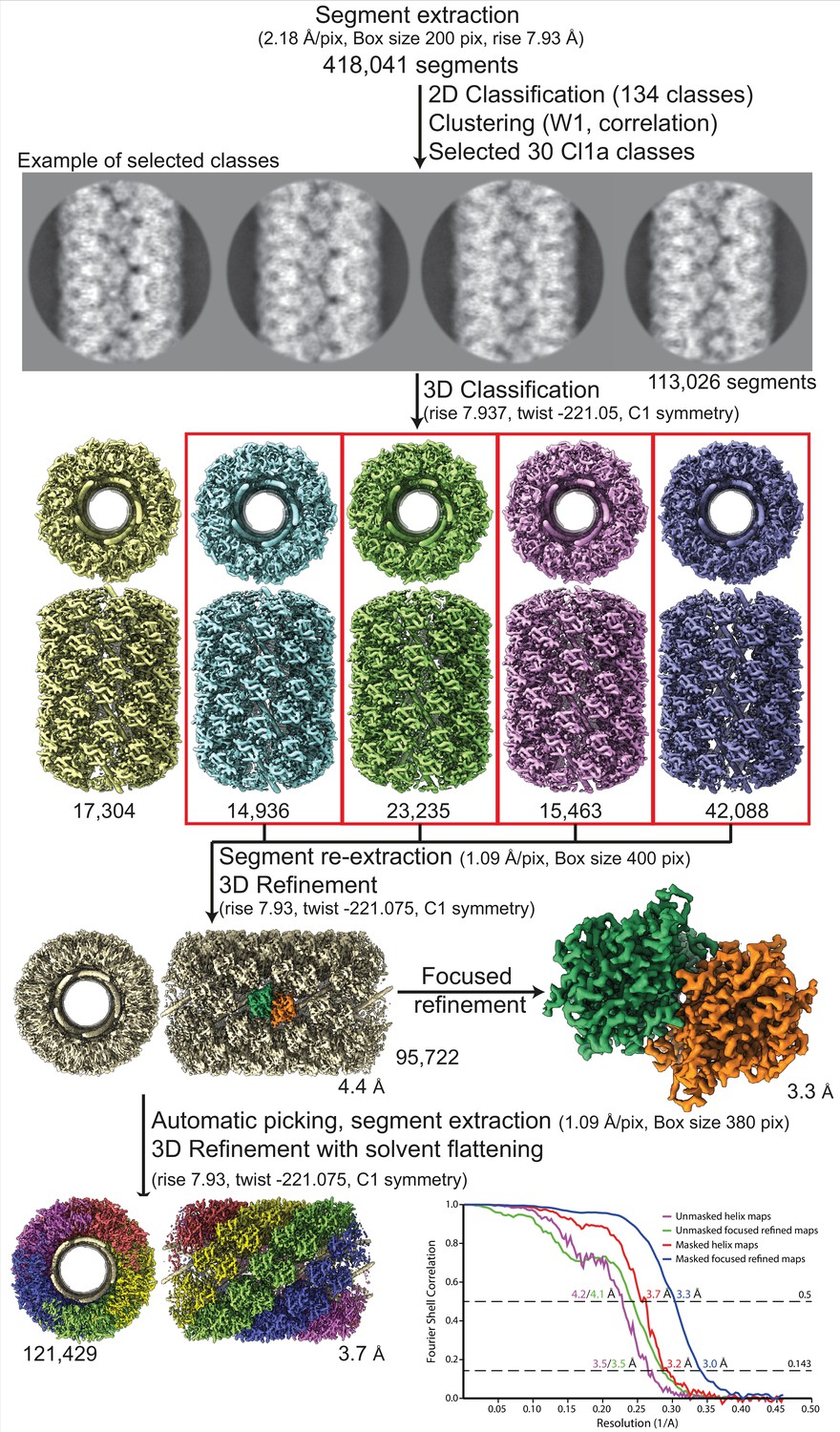
Workflow of the Cl1a compact helix reconstruction process and fitting.
Segment extraction was performed with a box size of 400 pixels (pix) binned twice (box size 200 pix, 2.18 Å/pix). The distance between consecutive boxes was equal to the axial rise calculated by indexation on the power spectrum. From 2D classification with 200 classes, 30 classes were selected for Cl1a after clustering see methods and Figure 1—figure supplement 6. First, 3D classification was carried out using the segments from 30 2D classes, helical symmetry parameters from the power spectrum indexation and a 300-Å featureless cylinder as 3D reference. 3D refinement of the four boxed 3D classes was achieved using one low-pass filtered 3D class as reference on the unbinned segments. One step of focused refinement (with solvent flattening) was performed using a low-pass filtered 3D reconstruction (before solvent flattening) as reference. 3D refinement was then performed. The resulting map was then used as model for automatic picking. A last 3D-refinement cycle was performed using as reference a featureless cylinder. The bottom right graph presents the Fourrier shell correlation (FSC) curves for the final 3D reconstructions (helical assembly and asymmetric unit).
Figure 2—figure supplement 2
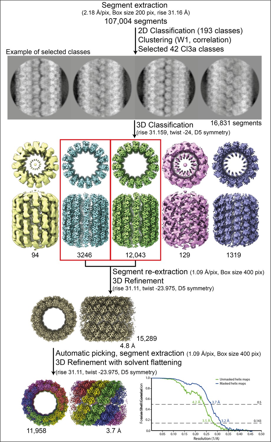
Workflow of the Cl3a relaxed helix reconstruction process and fitting.
Segment extraction was performed with a box size of 400 pixels (pix) binned twice (box size 200 pix, 2.18 Å/pix) using the rise obtained from the power spectrum indexation (see methods). From 2D classifications with 200 classes, 42 classes were selected for Cl3a after clustering (see methods and Figure 1—figure supplement 6). First, 3D classification was carried out using the 42 2D classes, with D5 symmetry, rise and twist from the power spectrum indexation and a featureless cylinder of 340 Å as reference. 3D refinement of the two 3D classes (red boxes) was achieved using one low-pass filtered 3D class as reference on the unbinned segments. The resulting map was used as model for automatic picking and segment extraction. Final 3D refinement was performed on unbinned segments using as initial reference a featureless cylinder with a last step of solvent flattening.
Figure 2—figure supplement 3
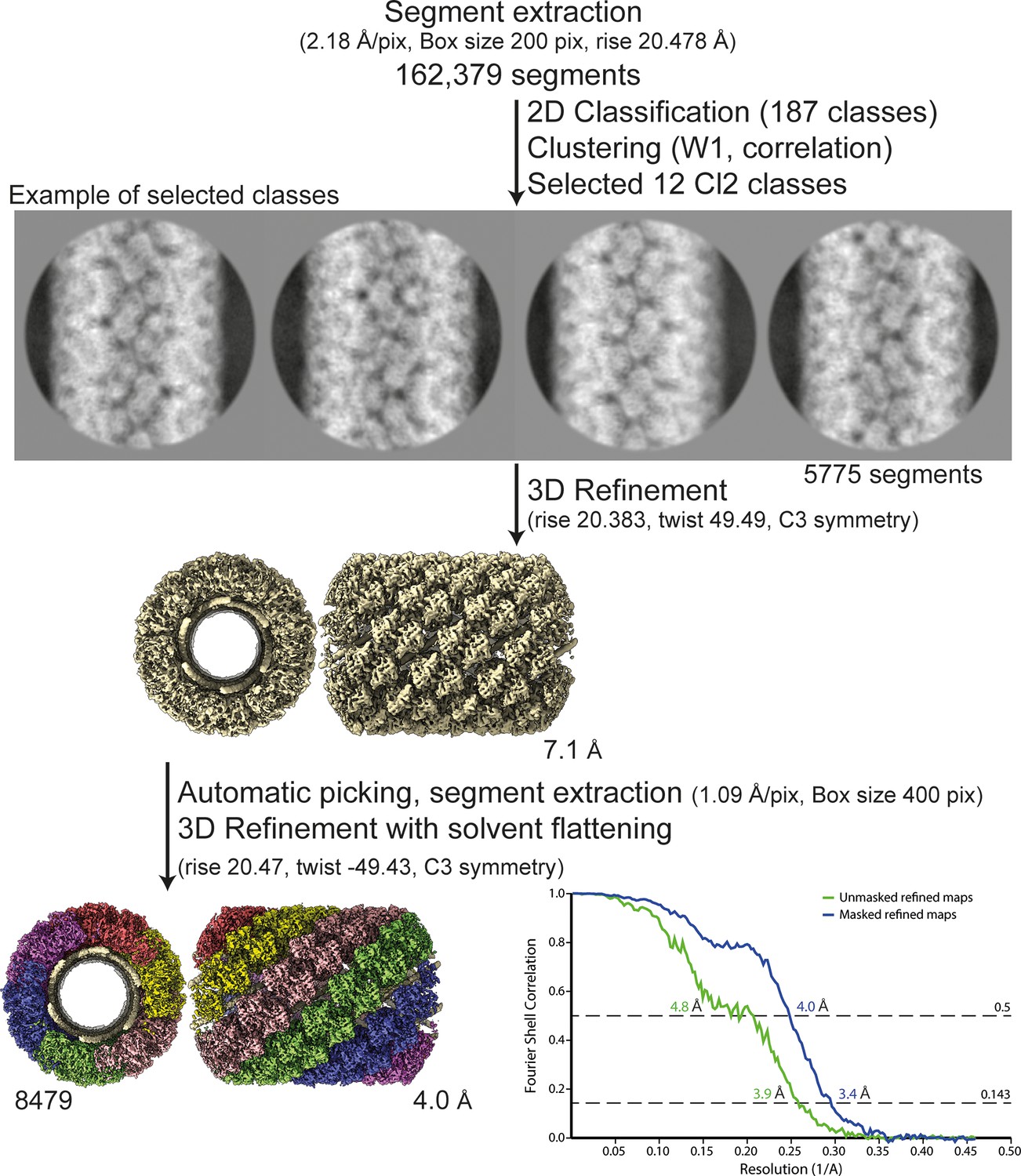
Workflow of the Cl2 helix reconstruction process and fitting.
Segment extraction was performed with a box size of 400 pixels (pix) binned twice (box size 200 pix, 2.18 Å/pix) using the rise obtained from the power spectrum indexation (see methods). From 2D classifications with 200 classes, 12 classes were selected for Cl2 based on correlation (see methods and Figure 5). First, 3D refinements combining 12 2D classes with solvent flattening, were performed with the C3 symmetry, rise and twist from the power spectrum indexation and a 330-Å featureless cylinder as reference. The resulting map was used as model for automatic picking and segment extraction on the unbinned segments. Final 3D refinement was performed on unbinned segments using as initial reference a featureless cylinder with a last step of solvent flattening.
Figure 2—figure supplement 4
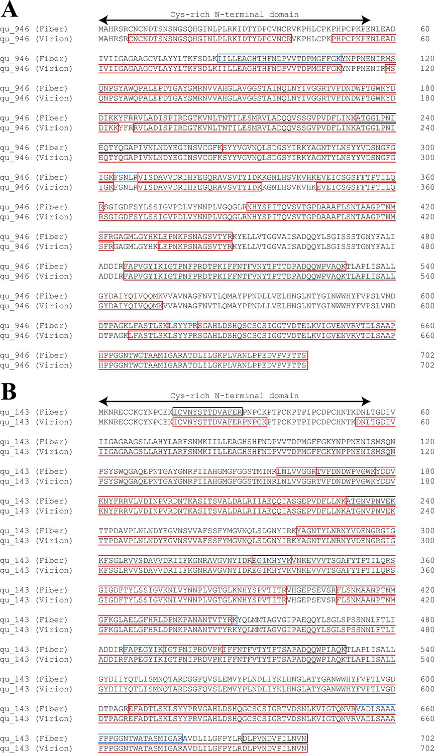
Comparison of sequence coverages for qu_946 (A) and qu_143 (B) obtained by mass spectrometry (MS)-based proteomic analysis of genomic fibers and total virions.
Identified peptides are highlighted in red, blue, and gray when identified, respectively, in three, two, and one replicate of the purified genomic fiber.
Figure 2—video 1
Illustration of the relaxation of the genomic fiber.
Figure 3 with 4 supplements

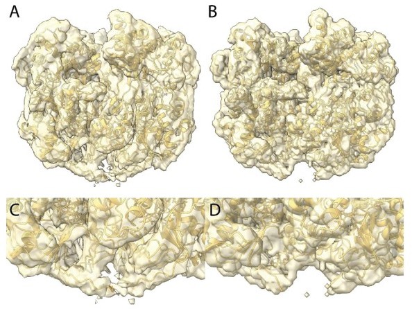
Maps of the compact (Cl1a and Cl2) genomic fiber structures.
(A) Cl1a EM map corresponding to the protein shell prior focused refinement is shown as a transparent surface and the five DNA strands as solid surface. One protein dimer strand is shown yellow except for one asymmetric unit (transparent yellow) to illustrate the dimer fit. The position of a second dimer (green) from the adjacent dimer strand is shown to emphasize that the DNA strand (gold) is lining the interface between two dimers. (B) Cartoon representation of GMC-oxidoreductase qu_946 dimers fitted into one of the Cl1a 5-start helix strands in the 3.7-Å resolution map. The map is shown at a threshold highlighting the periodicity of contacts between the dsDNA and the protein shell. Charged distribution on surface representation of Cl1a protein shell made of qu_946 dimers (C) or qu_143 dimers (D). Cartoon representation of qu_946 (E) and qu_143 (F) fitted into the Cl1a cryo-electron microscopy (cryo-EM) maps highlighting the interacting residues (given as stick models) between each monomer and one dsDNA strand. The isosurface threshold chosen allows visualization of density for the manually built N-terminal residues, including terminal cysteines (stick model), of two neighboring monomers that could form a terminal disulfide bridge. (G) Zoom into the 3.3 Å resolution focused refined Cl1a map illustrating the fit of the side chains and the FAD ligand (Figure 3—video 1). (H) Cartoon representation of the DNA fitted in the focused refined DNA only map (Figure 3—figure supplement 2). (I) Focused refined Cl1a map colored by monomer, next to a cartoon representation of the qu_946 dimer (α-helices in red, β-strands in blue, and coils in yellow). Secondary structure elements are annotated in both representations (H: helix, B: beta-strand).
Figure 3—figure supplement 1
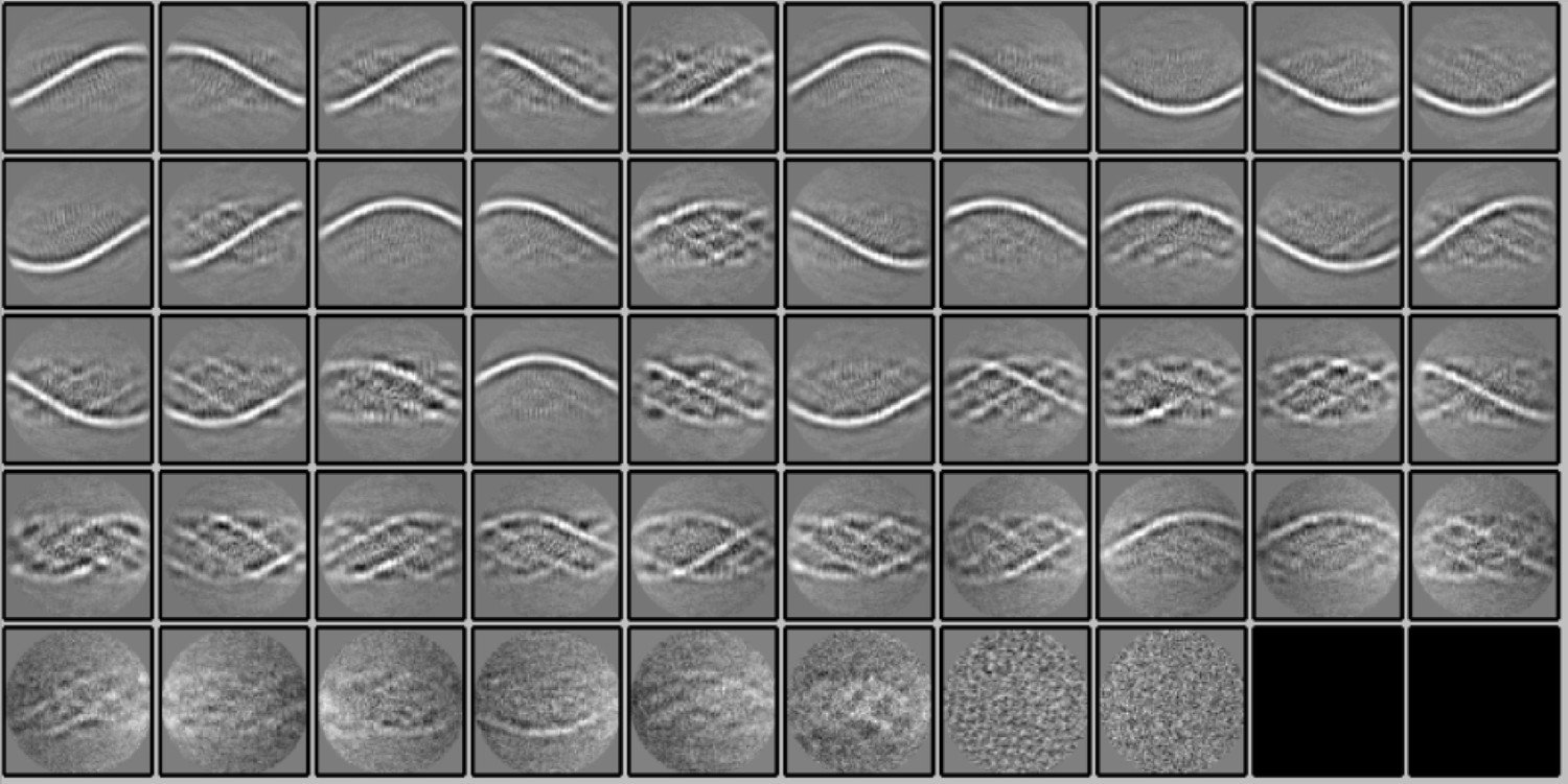
2D classification of subtracted segments.
Fifty 2D classes (2 empty) were obtained after reference-free 2D classification in Relion 3.1.0 of segments (box size of 400 pixels) of the Cl1a genomic fibers after signal subtraction to keep only the information of the DNA strands inside the fiber. The 2D classes show the enhancement of the signal corresponding to the DNA.
Figure 3—figure supplement 2
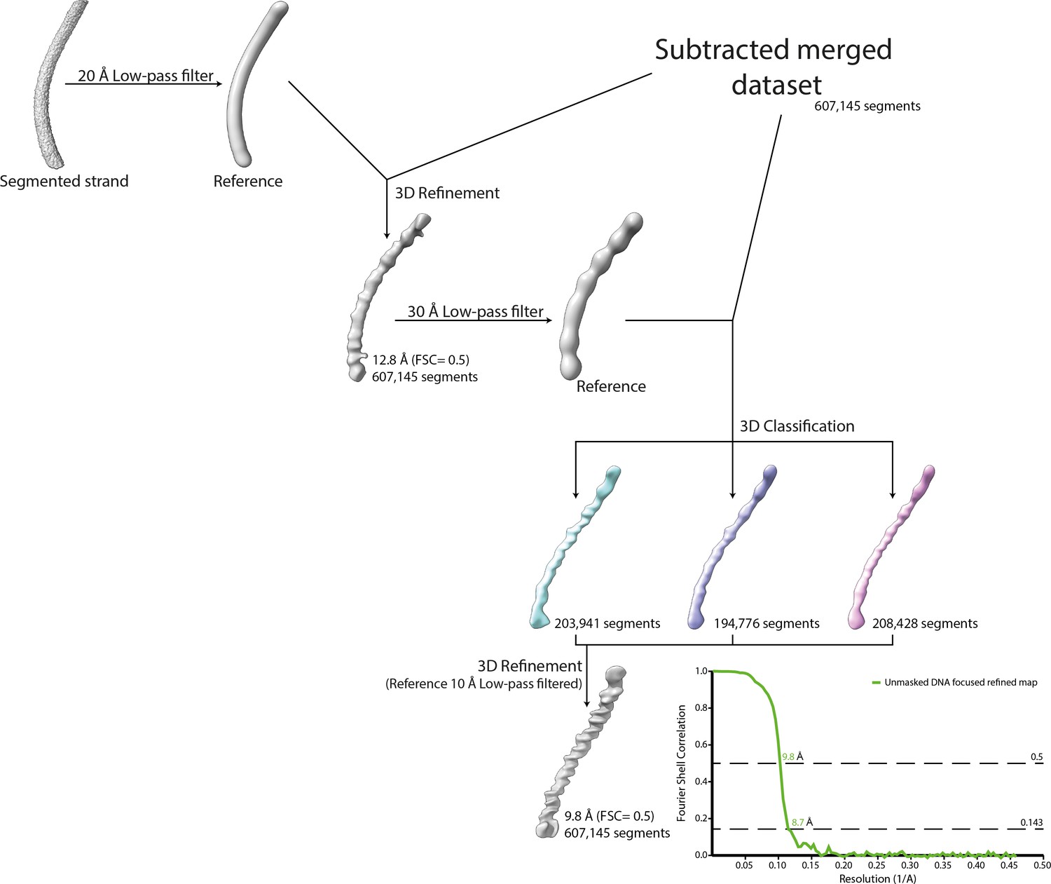
Workflow of the DNA strand focused refinement process.
One strand segmented from the 5-start compacted map (Cl1a) was low-pass filtered at 20 Å and used as reference for 3D refinement of the dataset corresponding to the merged dataset of the individually subtracted five strands. The result of the refinement was low-pass filtered at 30 Å and used as reference for 3D classification. The best 3D class was further refined leading to a focused refined map of the DNA strand.
Figure 3—video 1
Illustration of the fit of the GMC-oxidoreductase into the asymetric unit focused refined Cl1a map.
Figure 3—animation 1
Illustration of the fit of the GMC-oxidoreductase into the asymmetric unit focused refined Cl1a map.
Figure 4
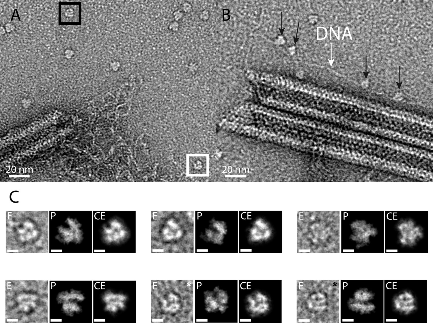
RNA polymerase could be associated to the genomic fiber.
(A) Micrograph of negative stained fiber with released DNA still being connected to a relaxed and broken fiber and adjacent scattered macromolecular complexes that might resemble RNA polymerases. (B) Strikingly, some of them (black arrows) appear to sit on a DNA strand (white arrow). (C) E, particle extracted from the NS-TEM image; P, projections of vaccinia virus RNA polymerase (6RIC and 6RUI, Grimm et al., 2019) structure in preferred orientation; CE, clean extraction (see Material and methods). White and black boxed corresponds to images with white and black asterisk (CE), respectively. Scale bar, 50 Å. Negative staining imaging may dehydrate the objects and change macromolecules volumes.
Author response image 1
Author response image 2

Author response image 3
Author response image 4
Author response image 5

Additional files
-
Supplementary file 1
Mimivirus Reunion genomic fibers data statistics (Liebschner et al., 2019).
- https://cdn.elifesciences.org/articles/77607/elife-77607-supp1-v3.docx
-
Supplementary file 2
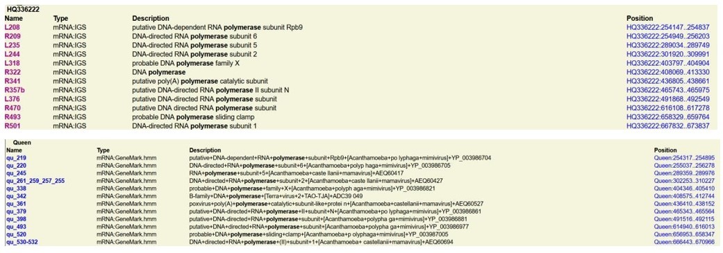
Mass spectrometry-based proteomic analysis of (A) three independent preparations of mimivirus genomic fiber and (B) one sample of purified mimivirus virions.
(ND: not detected). RNA polymerase subunits are marked in red.
- https://cdn.elifesciences.org/articles/77607/elife-77607-supp2-v3.docx
-
Supplementary file 3
Contacting residues for each GMC oxidoreductases in the different maps.
Conserved or divergent amino acids are color coded in green or in red, respectively.
- https://cdn.elifesciences.org/articles/77607/elife-77607-supp3-v3.docx
-
Supplementary file 4
Data acquisition parameters for cryo-electron microscopy (cryo-EM).
- https://cdn.elifesciences.org/articles/77607/elife-77607-supp4-v3.docx
-
Transparent reporting form
- https://cdn.elifesciences.org/articles/77607/elife-77607-transrepform1-v3.docx
Download links
A two-part list of links to download the article, or parts of the article, in various formats.
Downloads (link to download the article as PDF)
Open citations (links to open the citations from this article in various online reference manager services)
Cite this article (links to download the citations from this article in formats compatible with various reference manager tools)
The giant mimivirus 1.2 Mb genome is elegantly organized into a 30-nm diameter helical protein shield
eLife 11:e77607.
https://doi.org/10.7554/eLife.77607


