Hydrodynamics of sponge pumps and evolution of the sponge body plan
- National Institute of Aquatic Resources and Centre for Ocean Life, Technical University of Denmark, Denmark
- Department of Mechanical Engineering, Technical University of Denmark, Denmark
- Department of Biological Sciences, University of Alberta, CW 405 Biological Sciences Building, Canada
- The Faculty of Marine Science, Ruppin Academic Center, Israel
- Computational Science and Engineering Laboratory, Swiss Federal Institute of Technology Zürich, Switzerland
Figures
Figure 1
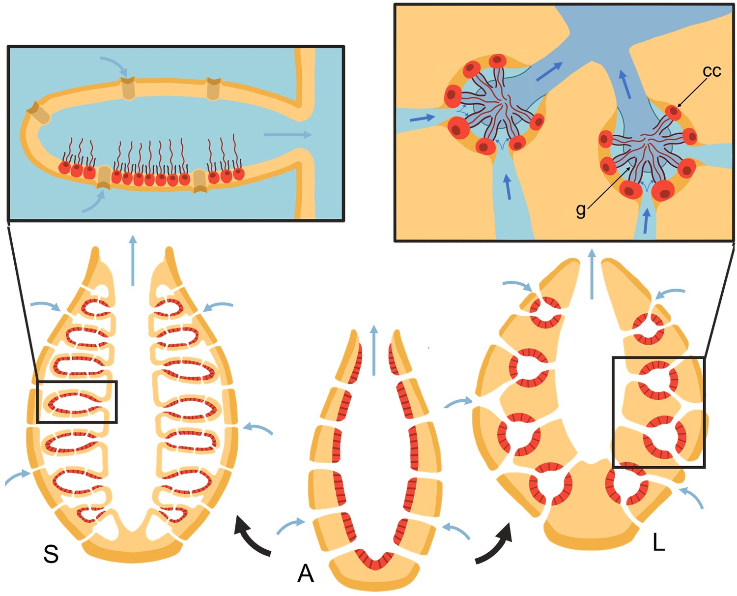
Schematic of sponge body types in ascon (A), sycon (S), and leucon (L) with evolutionary view of grades of morphological complexity in calcareous sponges (black arrows).
Insets show zoom-in water path (blue arrows) into the chambers in sycons and leucons, where in the latter, water is forced to go through collar filters (black) of choanocytes (red, cc) due to the presence of a physical gasket (g).
Figure 2
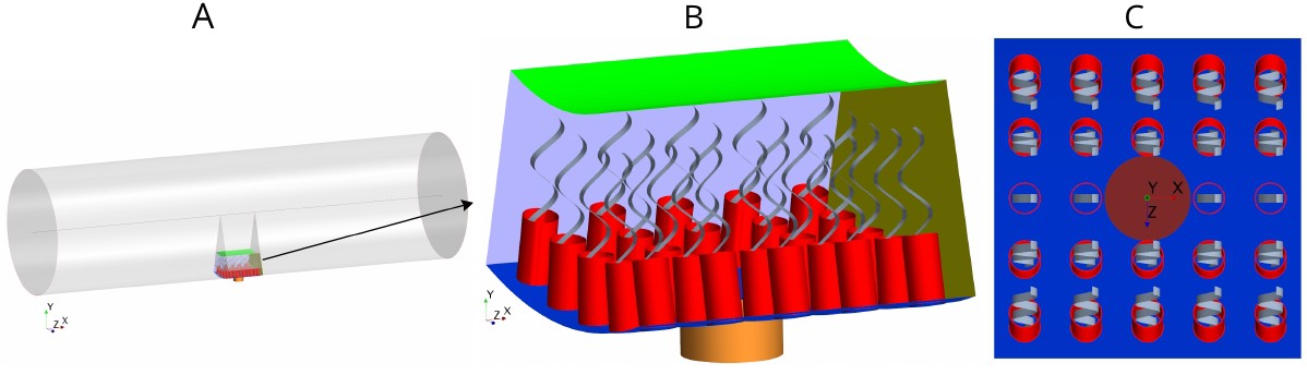
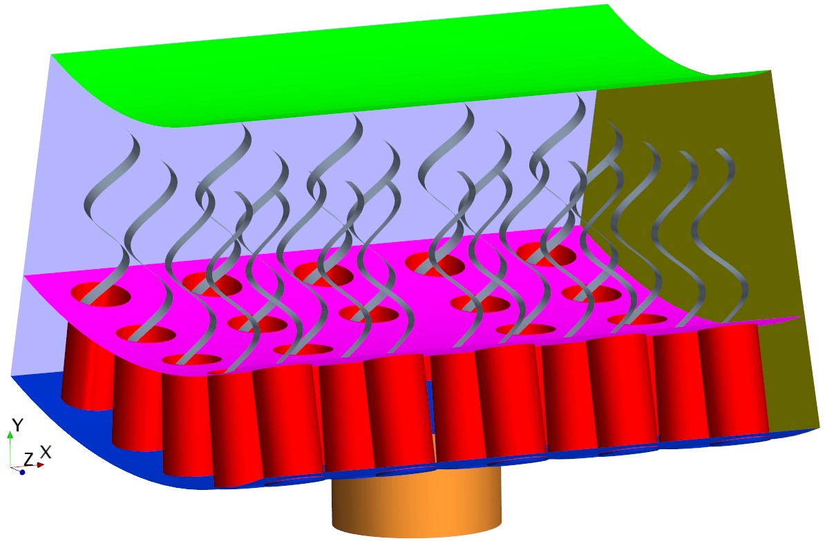
Morphology of the modeled flagellated chamber in calcareous sponges.
(A) The computational domain is a wedged section into the cylindrical, ascon-like flagellated chamber (85 µm in diameter). (B) A side view magnification of the modeled section. The water is pumped into the domain through a central tubular ostium, its inlet (brown, shown in C) is subjected to a uniform pressure and its surface (orange) to no-slip boundary conditions. The domain includes 24 porous collars (red) with 24 flagella (gray) attached to the inner surface of the chamber (blue) and subjected to no-slip boundary conditions. Two sides of the domain that are perpendicular to the x axis (olive, for clarity only one side shown) are subject to periodic boundary conditions, and the other two sides that are parallel to both the x and y axis (light blue, one side shown) are subjected to symmetric boundary conditions. The water leaves the domain from the top (green, subjected to a uniform pressure boundary conditions) into the chamber core. (C) Top view showing arrangements of the inlet and nearby collars.
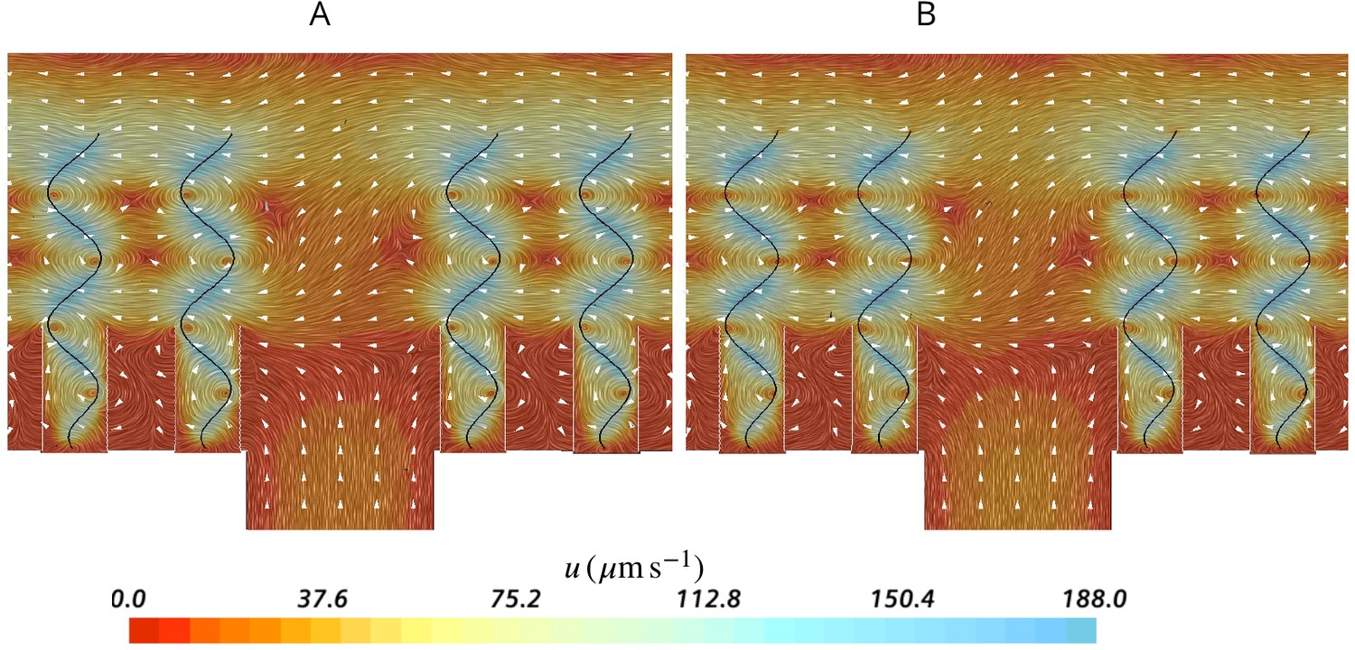
Figure 3
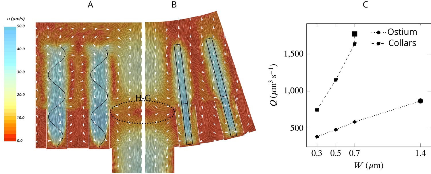
Simulated flow field inside the chamber.
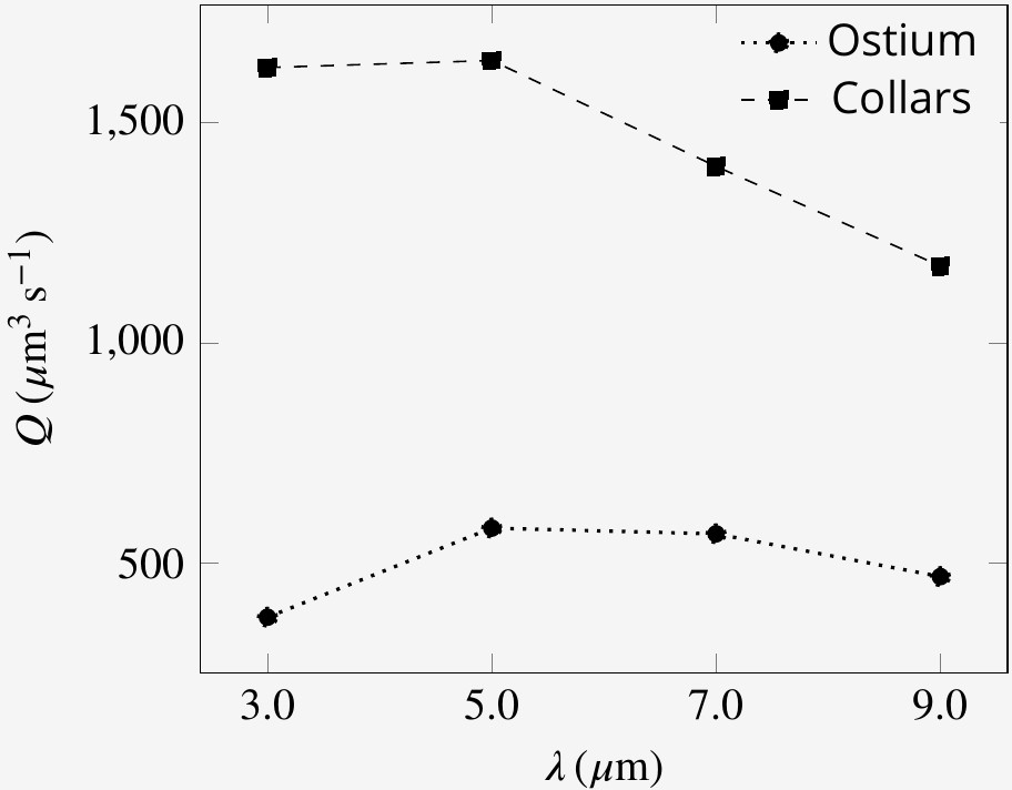
The averaged velocity field is plotted along the xy-plane (A) and yz-plane (B). Colors represent water velocity magnitude according to the color bar at the side; flow direction is indicated by white arrows; the flagella are indicated by black lines and the collars by gray lines. Due to the symmetry with respect to the yz-plane only one half of each of the planes is shown. A zone of stagnant water is formed by the backflow in the relatively large spacing between the flagella and above the ostium (H–G). This backflow serves as an effective ‘hydrodynamic gasket’ that forces the inflow through the collars. (C) Pumping rate (Q) through the ostium and filtration rate through the collars (Q) for different width (W) of the flagellar vane. The larger symbols correspond to the case where the vane width is 1.4 µm on the unconfined part of flagellum and 0.7 µm on the confined part.
Figure 4
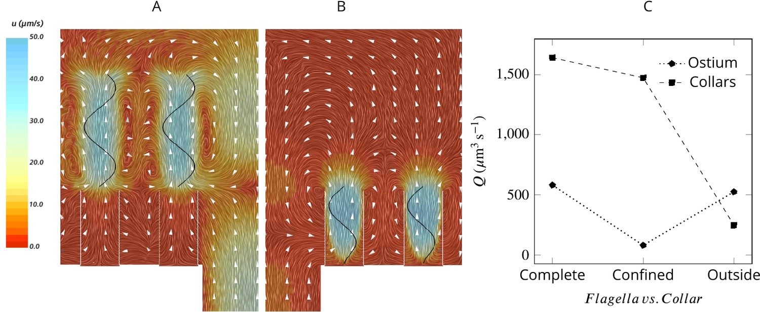
Averaged velocity field for two hypothetical cases: (A) only the unconfined part of the flagella exists, and (B) only the confined part of the flagella exists.
A comparison of the pumping and filtration rates provided in (C) demonstrate that unconfined flagella contribute substantially to the pumping rate into the chamber, but not through the collars. On the other hand, the confined region of the flagella draws in the flow through the collars and have a minor effect on the pumping rate.
Figure 5
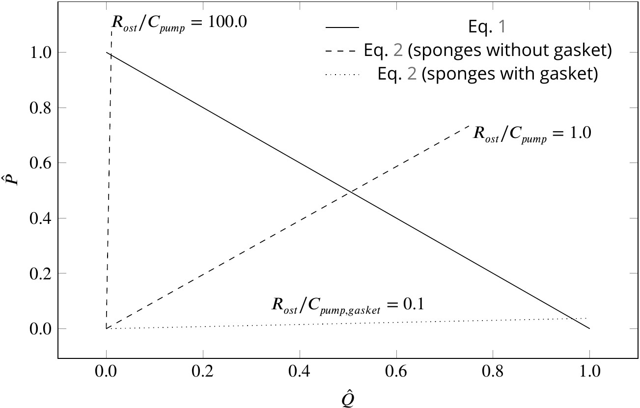
Dimensionless pump (solid line) and system (dashed and dotted lines) characteristics for different pumping units and canal systems in sponges.
At their operating condition (intersection of the pump and system lines), pumping units lacking a physical gasket deliver half of their maximum pumping capacity (). Functionality of such pumps would be impaired if connected to highly resistive canal system (). At such hydrodynamic conditions, a modification of the pump to that of leucon type having a physical gasket () lowers the slope of the system curve (), resulting in an efficient pumping at their operating condition.
Figure 6
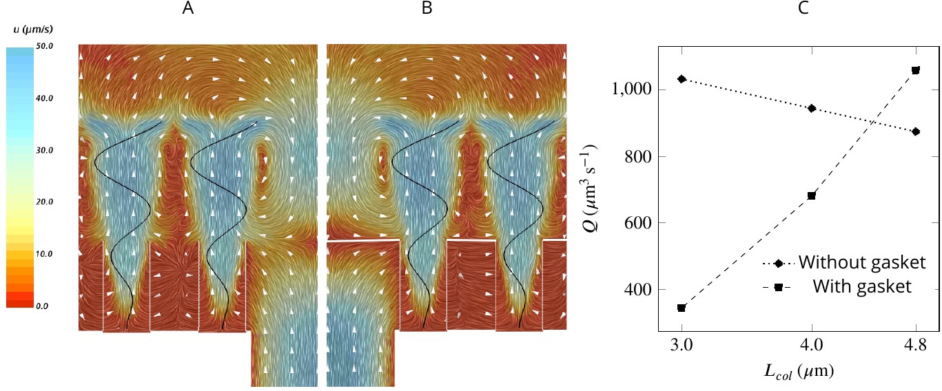
A comparison of mean velocity fields and the performance of (A) a hydrodynamic, and (B) a physical gasket (both with an increased amplitude of the flagella beat waveform and collar length of 4.8 µm).
(C) The volume flow rate through the ostium for different collar lengths. Inclusion of the physical gasket does not significantly affect the flow pattern inside the chamber. In sponges with relatively short collars (calcareous sponges), choanocytes pump more through the ostium the shorter the collar but increasing less through the collars (C).
Figure 7
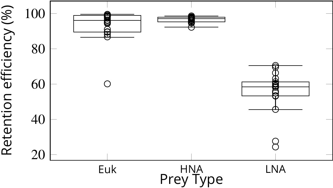
Retention efficiency (%) of different prey types counted by flow cytometry in the water inhaled and exhaled by Sycon coactum.
Euk are small nano and pico eukaryotic algae; HNA and LNA are non-photosynthetic bacteria with high and low nucleic acid content, respectively. Centre lines in each box show medians; box limits indicate the 25th and 75th percentiles; whiskers represent local minima and maxima, that is, they extend to data points that are less than 1.5 × IQR away from the 25th and 75th percentiles (IQR is the interquartile range), outliers are represented by dots.
-
Figure 7—source data 1
Sycon feeding and filtration.
- https://cdn.elifesciences.org/articles/61012/elife-61012-fig7-data1-v2.zip
Appendix 1—figure 1
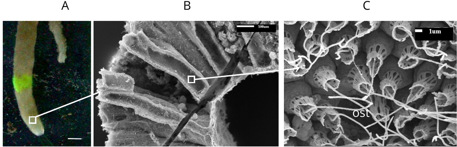
Calcareous sponge Sycon coactum.
(A) In natural habitat (scale bar: 1 cm). (B) A fracture across the body of the sponge showing relatively large cylindrically shaped chambers. (C) An ostium (ost) with the surrounding choanocytes in the chamber. Note that although flagella here appear as smooth, they do have a vane as shown in Appendix 1—figure 2.
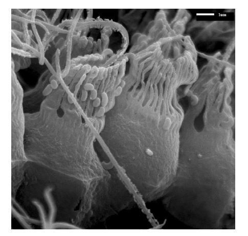
Appendix 1—figure 2
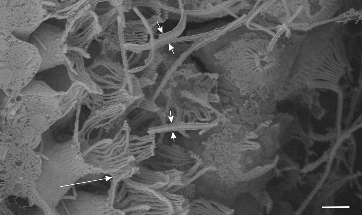
Observation of vane in the calcareous sponge Sycon coactum (scale bar: 2 µm).
The flagellar vane appears as two symmetrical wing-like projection (short arrows). Some mesh structure (long arrow) appears locally between collars, attached not to the collar tips, but rather lying further down the collar and attaching to the glycocalyx mesh that occurs between collar microvilli; it possibly functions to guide flow to the collar microvilli filters.
Appendix 1—figure 3
Snapshots of velolicty field for cases where the flagellum is extensible (A) and inextensible (B).
Appendix 1—figure 4
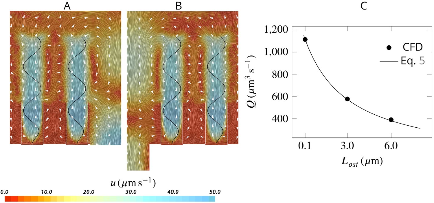
Effect of ostia length and diameter on the pumping rate and the backflow in the core of the region, and thus the position of the stagnation area.
A very short and wide ostium (A) increases the pumping rate, but at the cost of a high level of flow bypassing the collar. A longer and narrower ostium (B), as observed in sponges, reduces the pumping rate but lowers the height of the stagnation area. (C) Validity of Equation 5 vs CFD results for three different length of the ostium.
Appendix 1—figure 5

Effect of collar elements spacing () on pumping rate () and volume flow rate () through the collars for different porosity levels of the collars.
is the maximum spacing between adjacent microvilli and the porosity is decreases to zero at the tip of the collars (see text).
Appendix 1—figure 6
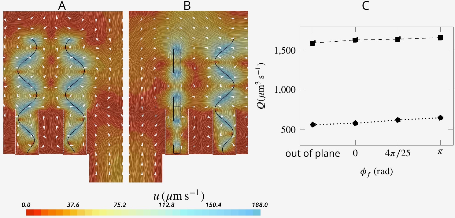
Snapshot of velocity fields when neighboring flagella beat completely out of phase (A, ) and in perpendicular planes (B).
Although snapshots of velocity differ for different scenarios, the pumping rate and flow through the collar filter are insignificantly affected by asyncronization among flagella (C).
Appendix 1—figure 7

Hydrodynamic interaction between the flagella.
A And B show average velocity fields for the cases with doubled beat frequency on the proximal compared to the distal flagella ( and ), and vice versa (A and B, respectively). Asynchronization between the proximal and distal flagella does not impair pumping. It does, however, affect the pumping rate, but the effect is due to the unequal contribution of the proximal and distal flagella on the pumping. (C) The presence of the distal flagella and thus their imparted momentum is important for creating the recirculation in the core of the region, without which the location of recirculation is shifted. The momentum may be imparted by flagella with different wavelength. (D) Averaged velocity field for wavelength .
Appendix 1—figure 8
Pumping rate and volume flow rate through the collars for flagella with different wavelength.
Appendix 2—figure 1
The simulation unit with presence of the gasket (pink).
Appendix 2—figure 2

Velocity (A) and pressure (B) fields in the cross section of the inner core cylinder.
The modeled cylinder is 200 µm long (=8 wedge-unit long), with diameter , where is the diameter of chamber and the height of the wedge geometry of Figure 2.
Appendix 2—figure 3
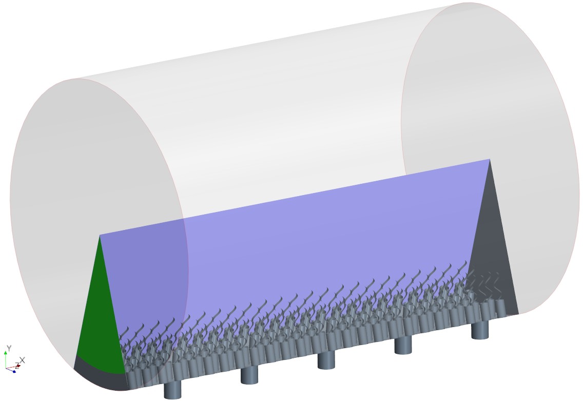
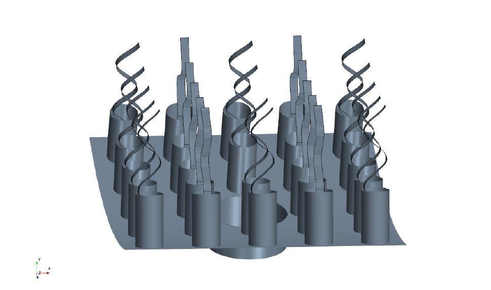
The simulation domain in an extended slice of the cylindrical chamber including five pumping units, that is, 5 ostia and 120 collar-flagella, closed (no-slip BC) at one end but open (uniform pressure BC) at the other end (green).
Appendix 2—figure 4
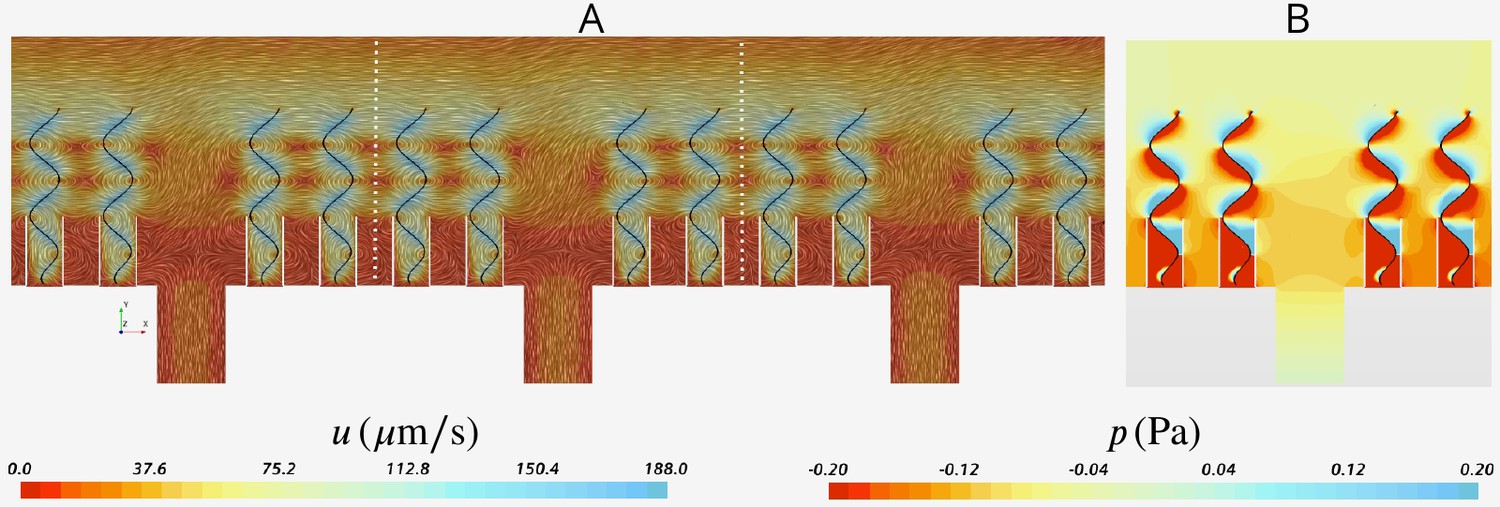
Snapshot of velocity and pressure fields for the simulation domain including five units depicted in Appendix 2—figure 3B.
(A) Velocity field in the three middle units (separated by white dash lines) shows the periodicity of the flow fields in these units independent of their location with respect to the outlet to the left (apopyle). (B) Pressure field in one single unit illustrating uniformity of the pressure above the flagella. Accordingly, the computational domain is reduced to one single unit using periodic and uniform pressure boundary conditions as shown in Figure 2.
Appendix 2—figure 5
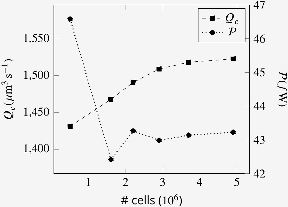
Mesh size independence of volume flow rate through the collars Qc and the power expenditure by the flagella at an arbitrary time step.
Author response image 1
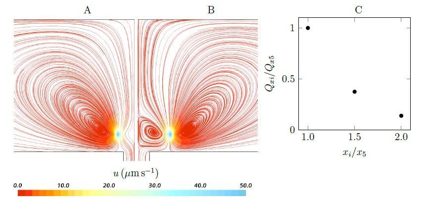
Streamlines and pumping rate of two stokeslet above a wall (at the height of hs = 4.7µm), either side of a hole, below a no-penetration boundary.
Note that due to the symmetry, the results are shown only in half of the plane. A weak recirculation region is formed above the hole as the horizontal distances xi increases (x5 = ±5µm (A) to x10 = ±10µm (B)), but it’s formation comes at the cost of a dramatically reduced pumping rate into the hole (C).
Author response image 2
Computational geometry where some flagella beat in a perpendicular plane.
Author response image 3
SEM image of calcareous ascon Leucosolenia eleanor showing flagellum with remnants of about ∼ 0.7µm wide vanes extending over the full flagellum length.
Videos
Video 1
Side view of passive particles entering into the chamber through the ostium and carried by the flow.
Particle color denotes its velocity according to the color scale at the bottom. Particles that arrive at the collar are removed from the simulation.
Video 2
Top view of passive particles entering into the chamber through the ostium and carried by the flow.
Particle color denotes its velocity according to the color scale at the bottom. Particles that arrive at the collar are removed from the simulation.
Video 3
The moving mesh (viewed in the xy-plane) inside the computational domain.
Appendix 1—video 1
Dye visualization of the jet from an osculum with a diameter of 2 mm.
Additional files
Download links
A two-part list of links to download the article, or parts of the article, in various formats.
Downloads (link to download the article as PDF)
Open citations (links to open the citations from this article in various online reference manager services)
Cite this article (links to download the citations from this article in formats compatible with various reference manager tools)
Hydrodynamics of sponge pumps and evolution of the sponge body plan
eLife 9:e61012.
https://doi.org/10.7554/eLife.61012


